

User Guide
2 or 3-Axis Manual Non-Contact
Measuring System


INTRODUCTIONHealth & Safety
Vision Engineering and its products conforms to the requirements of the EC Directives on Waste Electrical and
Electronic Equipment (WEEE) and Restriction of Hazardous Substances (RoHS).


CONTENTSPACKING CONTENTS
Head pack 1
Stand pack 1
Stage pack 1
Accessories packs 2
Illumination and objectives pack 2
QC-200/300 microprocessor pack 3
QC-5000 microprocessor pack 3
ASSEMBLY
Stage assembly 4
Ringlight attachment 5
Macro EPI attachment 5
Macro EPI and ringlight attachment 6
Micro EPI and lens turret attachment 6
Attaching the head only 7
Mounting camera to rear 7
Mounting camera to side for image capture 8
Attaching the anti-glare shield 8
Inserting the illuminator lamp 9
Inserting the stage glass 10
Connecting the fibre optic cable to the illuminator 11
QC-200/QC-300 microprocessor assembly 12
Cable connection points for the manual QC-200/QC-300 system 13
Interconnection diagram for manual Hawk system with QC-200 14
Interconnection diagram for manual Hawk system with QC-300 15
Interconnection diagram for Hawk system with manual QC-5000 16
Interconnection diagram for Hawk system with QC-5000 VED 17
SETTING UP
Manual system controls 18
Align head to stage 18
Stand levelling 19
Stage glass levelling 19
Camera Setup 19
OPERATION
Objective lens 20
Episcopic illuminator 21
LED Ringlight 21
Control box 22
LED illuminator specification 22
Substage 23
Taking a measurement (QC-200) 23
Taking a measurement (QC-300/QC-5000 VED) 24
Good working practices 24
CONTENTS

ROUTINE MAINTENANCE
Graticule adjustment 25
Changing the illuminator lamp 26
General care 27
Consumable and replacement parts 27
Environmental conditions 27
ACCESSORIES & OPTIONS
OTHER SOLUTIONS FROM VISION ENGINEERING
Stereo inspection systems 29
Non-contact measuring systems 30
SERVICE & CALIBRATION RECORD
WARRANTY
CONTENTS
PACKING CONTENTSSee packing list to clarify contents of delivery.
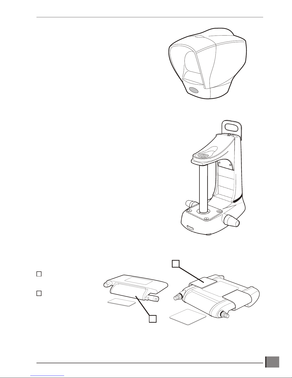
Head pack
Stand pack
Stage pack
200mm x 150mm
(8" x 6")
150mm x 150mm
(6" x 6")
www.visioneng.com/support Hawk 2 or 3-Axis Manual Non-Contact Measuring System
PACKING CONTENTS
1
1
2
1
2
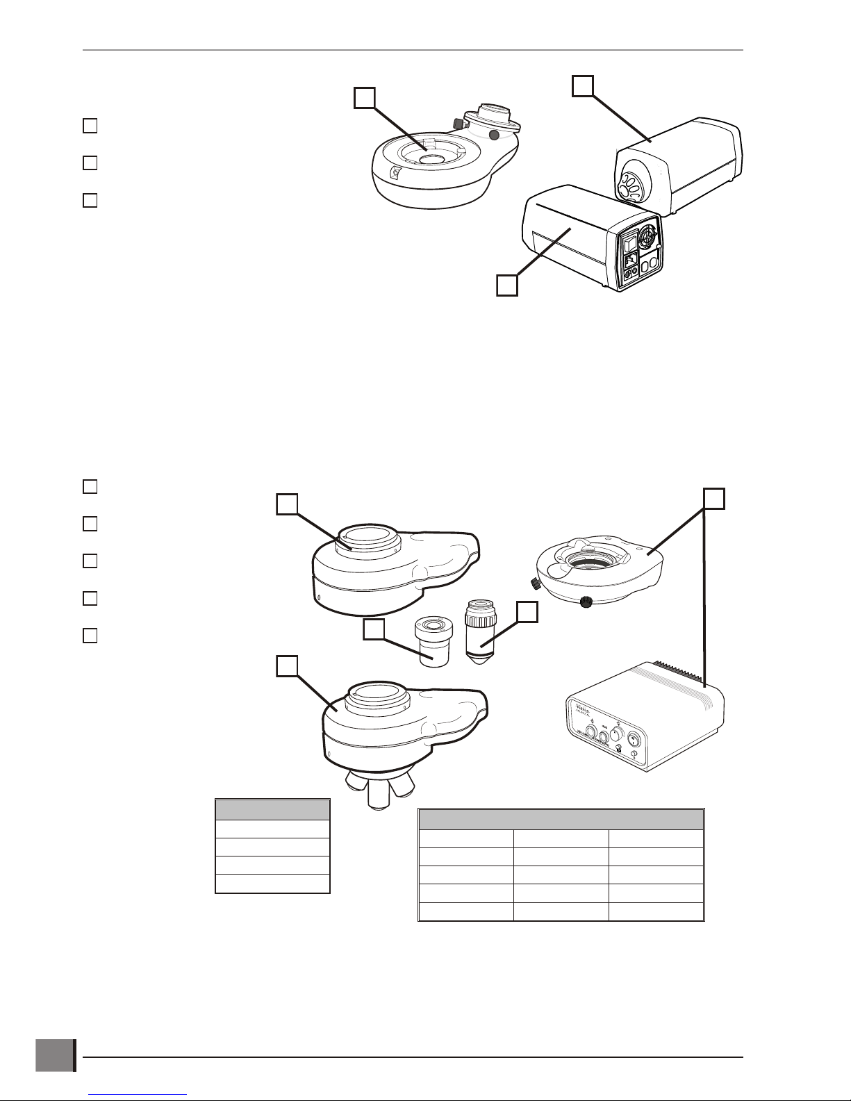
Accessories packs
Photographic adaptor
Illuminator
Power supply
Illumination and objectives pack
Macro EPI
Ringlight and Control box
Micro EPI/Turret Assembly
Macro Lens
Micro Lens
Hawk 2 or 3-Axis Manual Non-Contact Measuring System www.visioneng.com/support
PACKING CONTENTS
2
Macro Lens Options
x1
x2
x5
x10
134
5
Micro Lens Options
Micro Micro LWD Micro SLWD
x5 x10 x20
x10 x20 x50
x20 x50
x50 x100
1231234
5
123
2
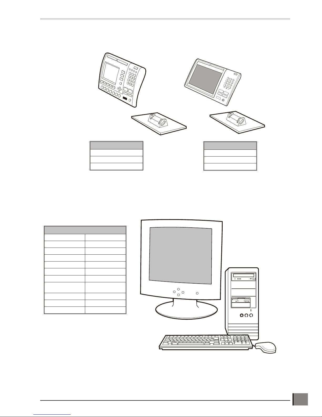
QC-200/300 microprocessor pack
QC-5000 microprocessor pack
www.visioneng.com/support Hawk 2 or 3-Axis Manual Non-Contact Measuring System
PACKING CONTENTS
3
QC-200 items included:
Power lead
Instruction manual
QC Quickie Test Slide
QC-300 items included:
Power lead
Instruction manual
QC Quickie Test Slide
QC-5000 items included
Manual Optional Manual VED
Instruction Manual Instruction Manual
Encoder Cable Encoder Cable
RS232 Comms Cable RS232 Comms Cable
2 x Power Leads 2 x Power Leads
QC-5000 Software QC-5000 Software
Windows Software Windows Software
Graphics Card
(pre-installed)
Drivers Disc
Additional Monitor
S-Video Cable
ASSEMBLYThe following paragraphs provide instructions on how to assemble the Hawk Measuring System. In most instances
the illustrations are self explanatory; where necessary the illustrations are supported by text.
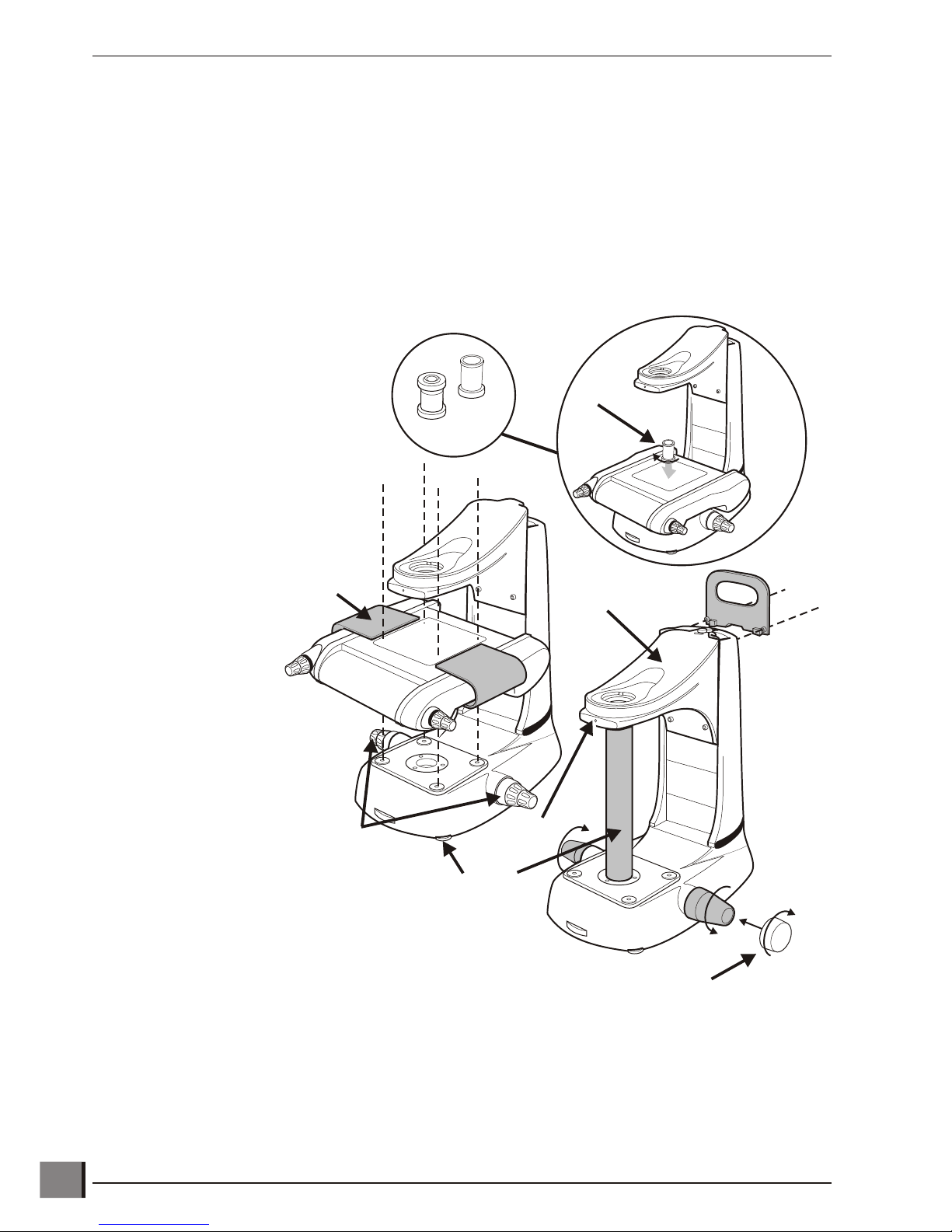
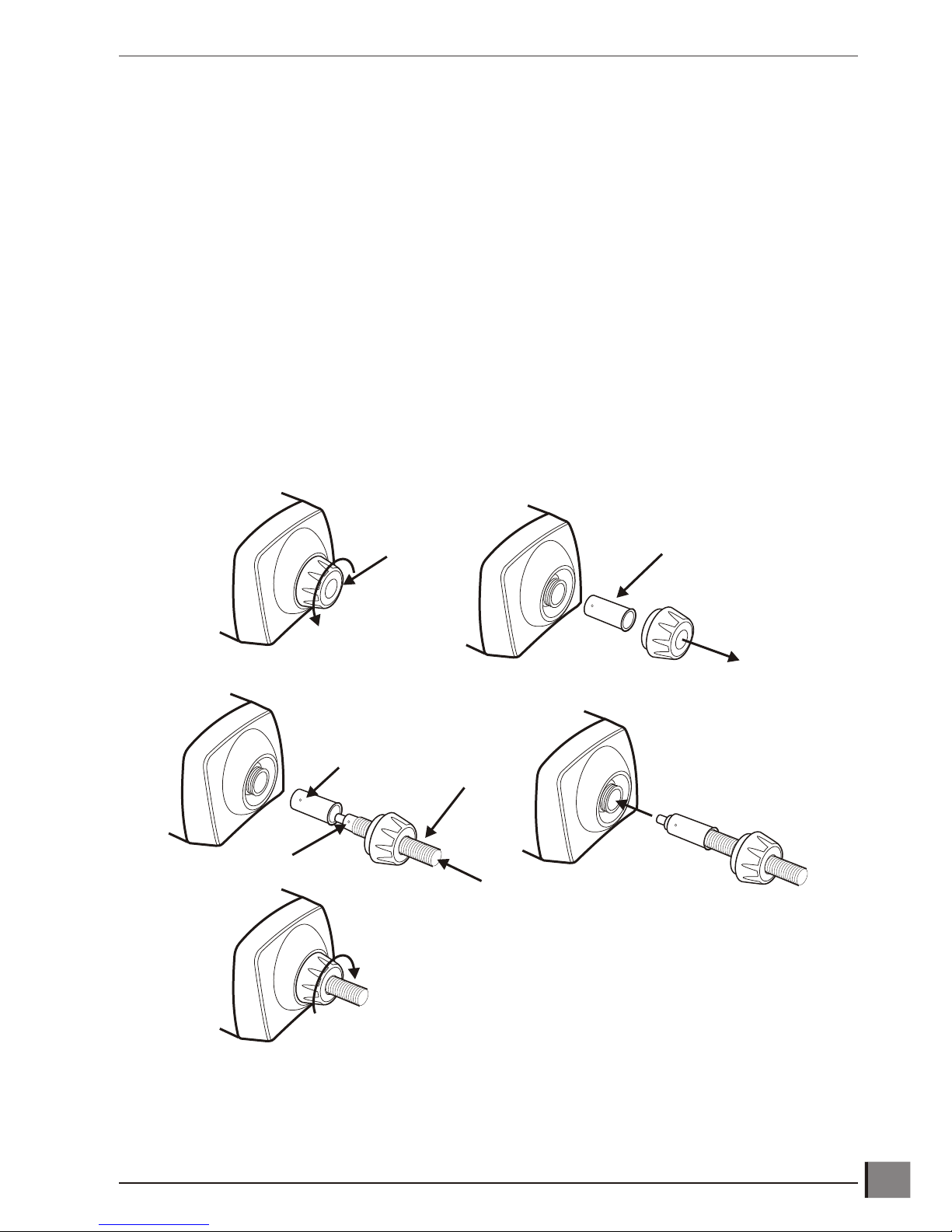
Stage assembly
To attach the Stage proceed as follows:
u Use the red transit handle and focus control covers to lift the stand into the required work position.
u Remove the red transit handle and focus
control covers. Screw the two focus
control collars u into position.
u Remove the grub screw v. Use the
focus controls w to raise the head
platform x until there is sufficient
room to unscrew and remove the
transit tube y.
u Using the red transit handles, lift the
stage into position and secure it
using the bolts provided
with the stand, not
the bolts that secure
the stage into the
transit box.
u Remove the stage
transit handles z.
u Adjust the stabilizing foot {
to support the stand base.
u Screw the required condenser
lens | through the stage and
into the stand.
Note: Micro condensers should only be used with micro
lenses when viewing a subject at stage glass level.
Hawk 2 or 3-Axis Manual Non-Contact Measuring System www.visioneng.com/support
ASSEMBLY
4
Micro
Macro
u
v
w
x
y
z
{
|
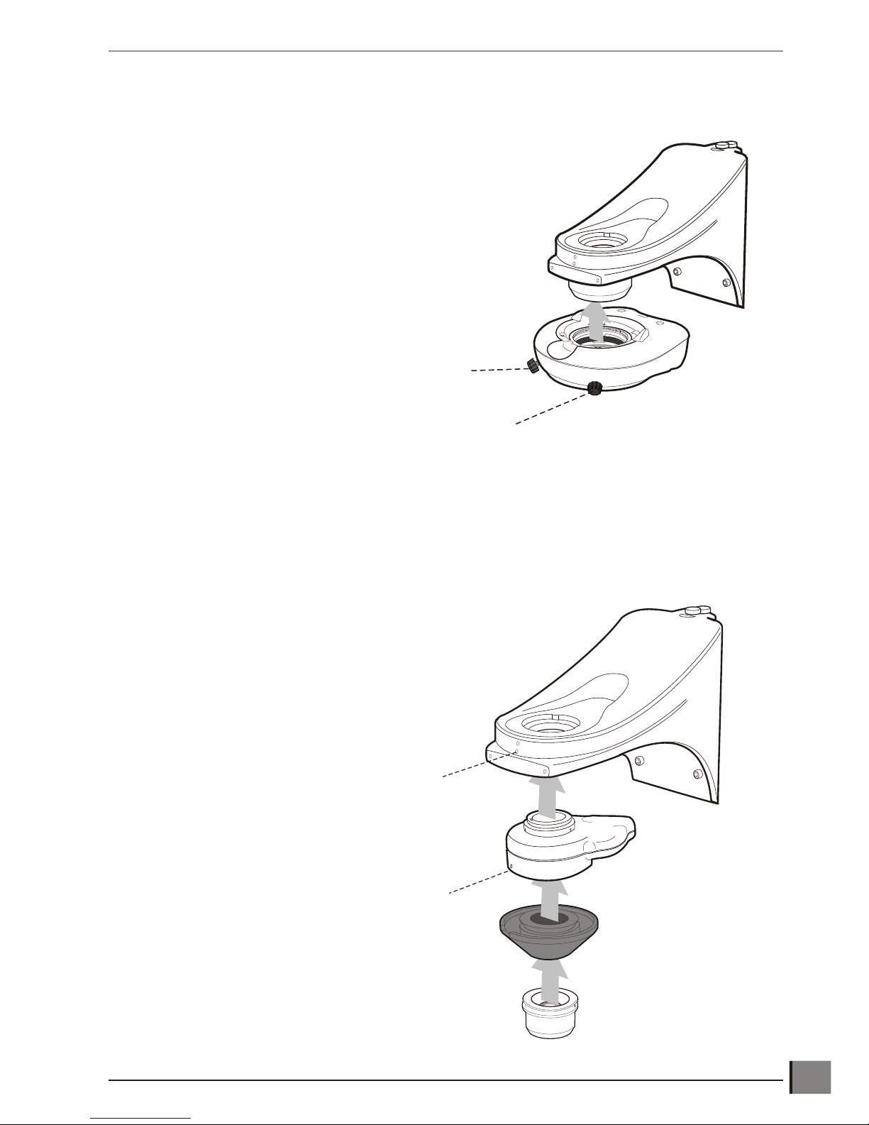
Ringlight attachment
Macro EPI attachment
Note: The same procedure is used to fit either the Macro EPI (illustrated) or the Micro EPI. The Micro
EPI cannot have an Objective Holder or Ringlight fitted.
www.visioneng.com/support Hawk 2 or 3-Axis Manual Non-Contact Measuring System
ASSEMBLY
5
Securing Screw
Grub Screw
Grub Screw
Securing Screw
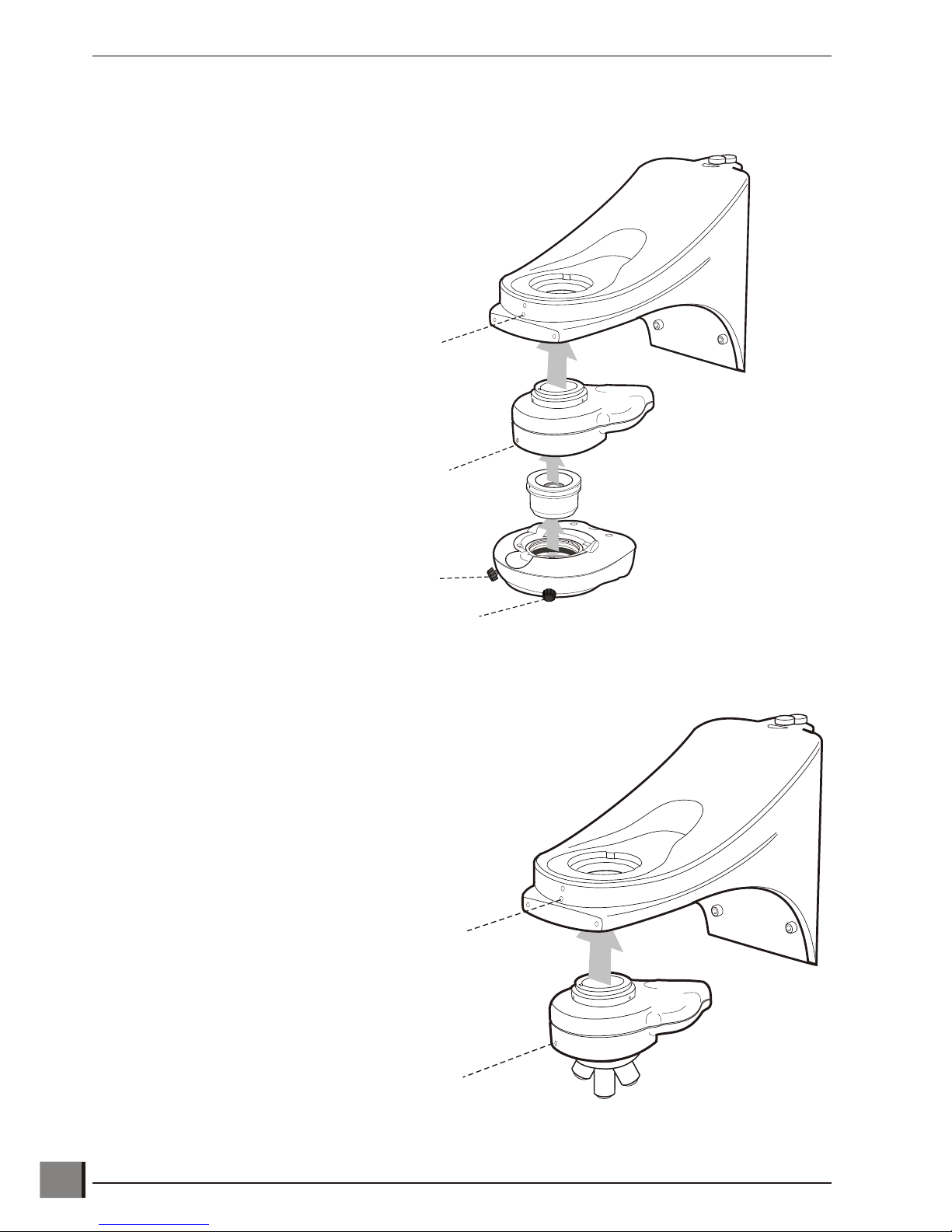
Macro EPI and ringlight attachment
Micro EPI and lens turret attachment
Hawk 2 or 3-Axis Manual Non-Contact Measuring System www.visioneng.com/support
ASSEMBLY
6
Grub Screw
Securing Screw
Grub Screw
Securing Screw
Grub Screw
Grub Screw

Attaching the head only
Mounting camera to rear
u Position photographic attachment between
the viewing head and its arm.
u Secure with the grub screws.
u Attach the adapter to the camera
and tighten 3 x grub screws if not
already fitted.
u Locate camera and adapter to the locking
plate (the locking plate must not be
overtight, but enough to hold).
www.visioneng.com/support Hawk 2 or 3-Axis Manual Non-Contact Measuring System
ASSEMBLY
7
Head
Connector
Head
Socket
Grub
Screw
Photographic
Attachment
Grub
Screws
Locking
Plate
Camera
Adapter

Mounting camera to side for image capture
Attaching the anti-glare shield
CAUTION: The Anti-Glare Shield is made of plastic and
must not be over tightened.
Hawk 2 or 3-Axis Manual Non-Contact Measuring System www.visioneng.com/support
ASSEMBLY
8
Photographic
Attachment
Camera
Interface
Centring
Screws
Focus
Adjustment
Head
Connector
Head Socket
Securing
Screws
Grub Screws

Inserting the illuminator lamp
u Press down the lamp/fan assembly release button u.
u Lift out the lamp/fan assembly v.
u Insert the lamp as shown w.
u Check that it is fully
pushed into the
lamp holder.
www.visioneng.com/support Hawk 2 or 3-Axis Manual Non-Contact Measuring System
ASSEMBLY
9
u
v
w
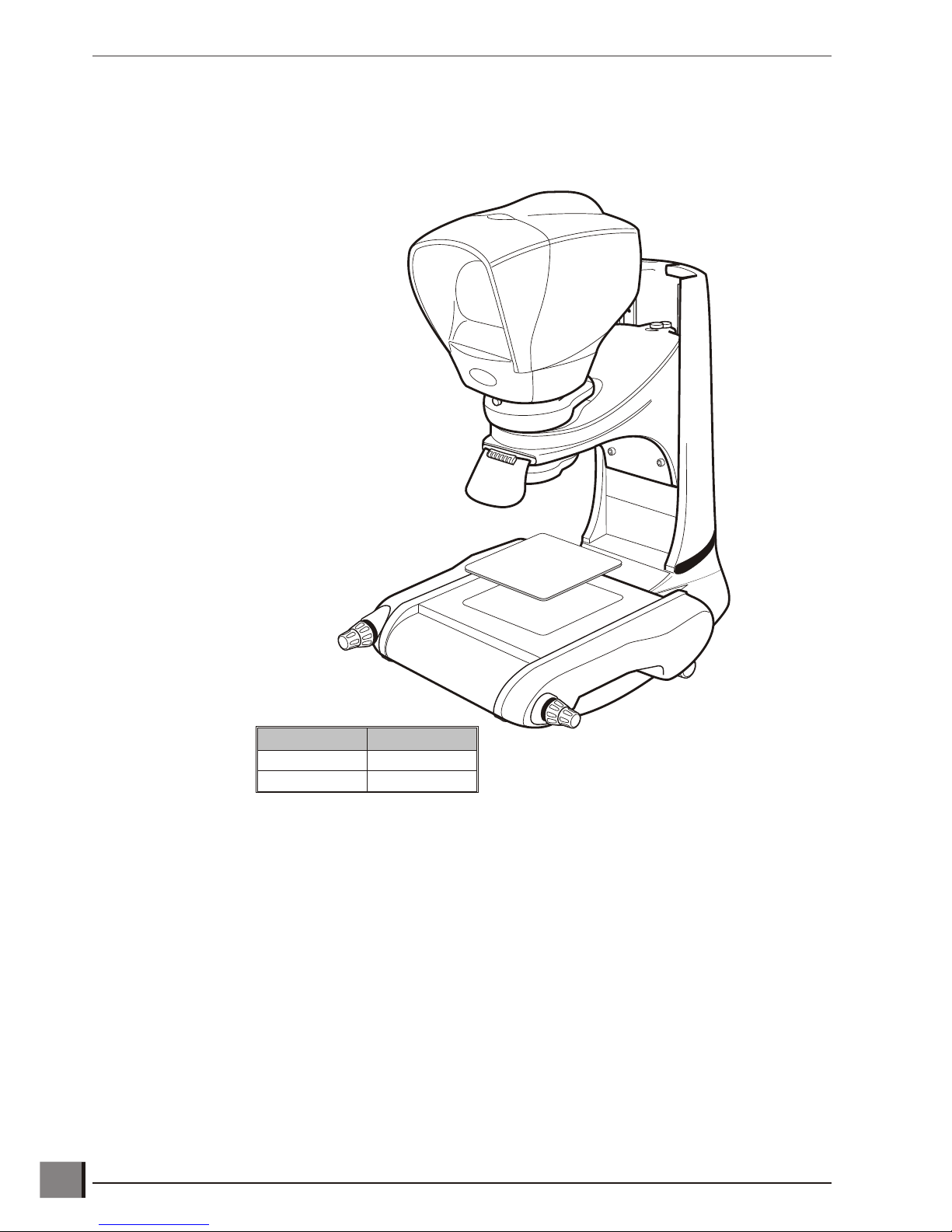
Inserting the stage glass
Note: The stage glass must be handled with care to avoid any fingerprint marks.
u Align the glass with it's bevelled edges against the springs.
u Check that the stage glass is in contact with all
four supports.
u To level the stage glass, refer to page 19.
Hawk 2 or 3-Axis Manual Non-Contact Measuring System www.visioneng.com/support
ASSEMBLY
10
Stage size Spring location
150 x 150mm Left & Back
200 x 150mm Left & Front
Connecting the fibre optic cable to the illuminator
u Unscrew the locking collar.
u Remove the locking collar and ferrule.
u Insert the fibre-optic cable through the locking collar and ferrule. Align the grub screw with the indent on the
cable and tighten the screw with the hexagonal/Allen key provided.
Note: The hexagonal/Allen key is taped to the base of the illuminator.
u Insert the cable and ferrule into the illuminator.
u Tighten the locking collar.
www.visioneng.com/support Hawk 2 or 3-Axis Manual Non-Contact Measuring System
ASSEMBLY
11
2
3
4
5
Fibre-Optic
Cable
Indent
Grub
Screw
Ferrule
1
Locking
Collar

QC-200/QC-300 microprocessor assembly
Cable connection points are shown on page 13.
Hawk 2 or 3-Axis Manual Non-Contact Measuring System www.visioneng.com/support
ASSEMBLY
12
Stand
Standard
Bolt
Shoulder
Bolt
Locking
Washer
NOTE:
Do Not Over-tighten
Spacer
Stand
Microprocessor
Microprocessor
Stand
Microprocessor
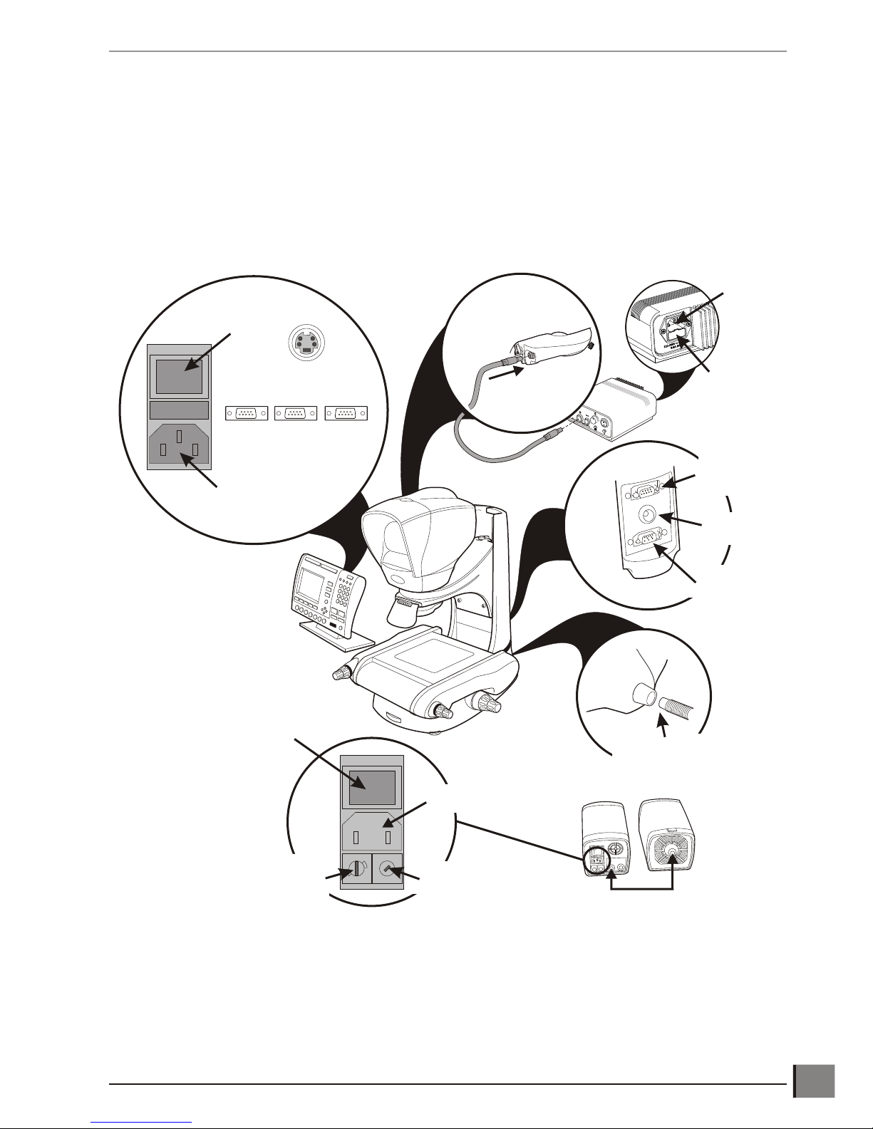
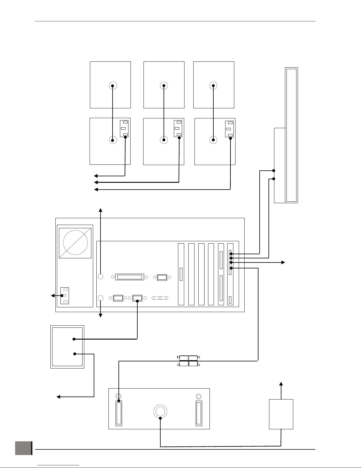
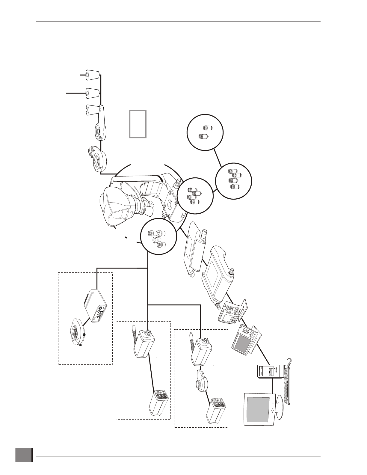
Cable connection points for the manual QC-200/QC-300 system
Refer to pages 14 and 15 for detailed connections.
Note: Ensure that the voltage selector is turned to the correct setting.
www.visioneng.com/support Hawk 2 or 3-Axis Manual Non-Contact Measuring System
ASSEMBLY
13
Mains
Input
Mains
On/Off
Switch
Fuse
Z Axis
Encoder
Head Power
Transformer
Z Axis
Motor
Sub-Stage Illuminator
Fibre-Optic Connector
DC Connection
red = 100W
blue = 150W
EPI = 100W
Sub-Stage = 100W
X Axis Y Axis Z Axis
S-Video (QC-300 only)
1
1
5
230
Voltage
Selector
Input
Power
Fuse
Mains
On/Off
Switch
Mains
Input
Ringlight Connection
Mains
Input
Input
Power
Fuse
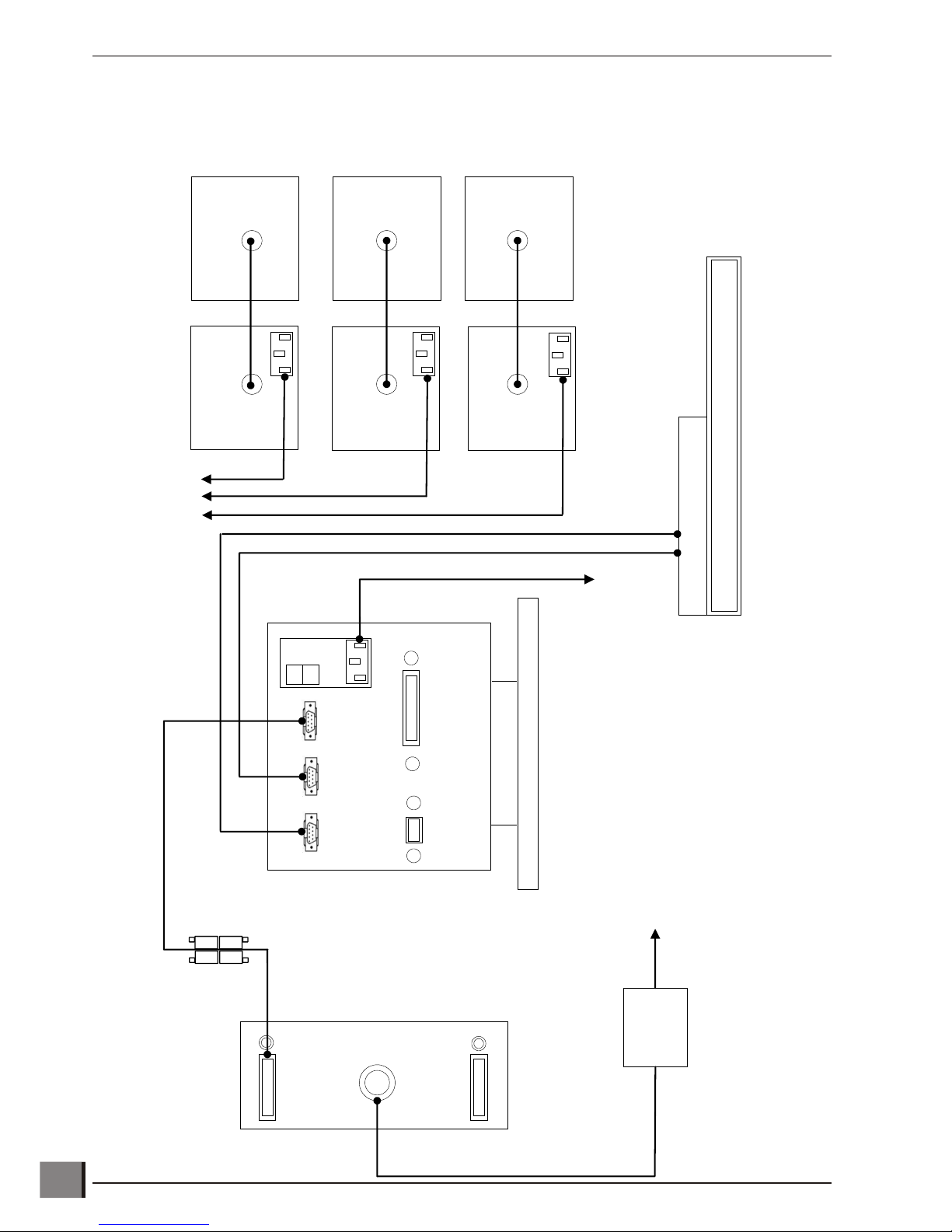
Interconnection diagram for manual Hawk system with QC-200
Hawk 2 or 3-Axis Manual Non-Contact Measuring System www.visioneng.com/support
ASSEMBLY
14
Substage Illumination
Light Source
LED Ringlight
Illuminator
Episcopic Illumination
Light Source
Substage PSU
LED Ringlight
Control Box
EPI PSU
XZY
XY
Mains Supply
Z Axis Encoder
Z Axis Motor
Hawk Stand
QC-200
Stage Encoders
Mains Supply
Mains Supply
Transformer
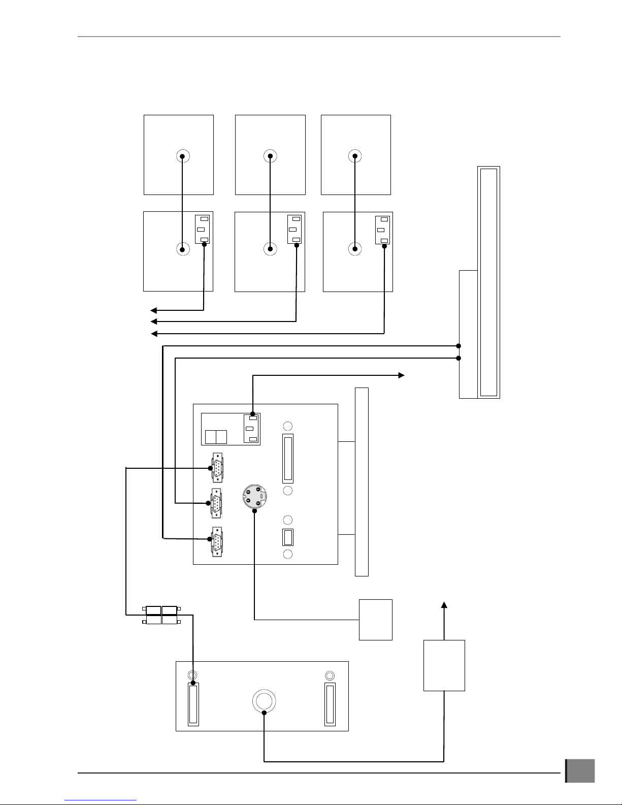
Interconnection diagram for manual Hawk system with QC-300
www.visioneng.com/support Hawk 2 or 3-Axis Manual Non-Contact Measuring System
ASSEMBLY
15
Substage Illumination
Light Source
Episcopic Illumination
Light Source
Substage PSU
EPI PSU
XZY
XY
Mains Supply
Z Axis Encoder
Z Axis Motor
Hawk Stand
QC-300
Stage Encoders
Mains Supply
Mains Supply
Transformer
Camera
S-Video Cable
LED Ringlight
Illuminator
LED Ringlight
Control Box
Interconnection diagram for Hawk system with manual QC-5000
Hawk 2 or 3-Axis Manual Non-Contact Measuring System www.visioneng.com/support
ASSEMBLY
16
Substage Illumination
Light Source
Episcopic Illumination
Light Source
Substage PSU
EPI PSU
X
Y
Mains Supply
Z Axis Encoder
Z Axis Motor
Hawk Stand
Stage Encoders
Mains Supply
Monitor
Transformer
To Footswitch
Keyboard
Mouse
Mains Supply
Head Power
Mains Supply
LED Ringlight
Illuminator
LED Ringlight
Control Box

Interconnection diagram for Hawk system with QC-5000 VED
www.visioneng.com/support Hawk 2 or 3-Axis Manual Non-Contact Measuring System
ASSEMBLY
17
Substage Illumination
Light Source
Episcopic Illumination
Light Source
Substage PSU
EPI PSU
X
Y
Mains Supply
Z Axis Encoder
Z Axis Motor
Hawk Stand
Stage Encoders
Mains Supply
Monitor No 1
Transformer
To Footswitch
Keyboard
Mouse
Mains Supply
Head Power
Mains Supply
Monitor No 2
Camera
S-Video Cable
LED Ringlight
Illuminator
LED Ringlight
Control Box
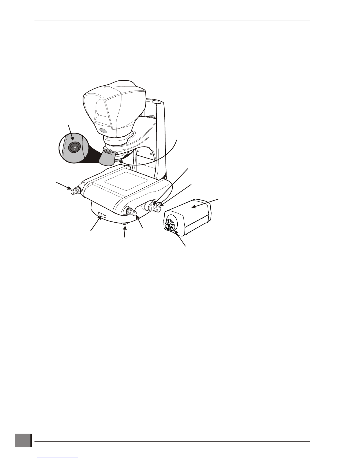
SETTING UPManual system controls
Turn on the illuminator power supplies and check that the LED at the centre of the head is illuminated.
The manual system controls are identified below.
Align head to stage
u Ensure that an objective lens is fitted.
u Ensure the head is switched on and then loosen it using an hexagonal/Allen key.
u Align the front edge of the gauge block (or straight edge) with the front edge of the stage glass.
u Rotate the head until the horizontal cross line is parallel with the rear edge of the gauge block (or straight edge).
u Lock the head in position with the hexagonal/allen key.
Hawk 2 or 3-Axis Manual Non-Contact Measuring System www.visioneng.com/support
SETTING UP
18
Fine
Focus
Control
Coarse
Focus
Control
Y Axis
Control
On/Off
Switch
X Axis
Control
Substage
Iris Control
Levelling
Foot
Illuminator Dimmer
Illuminator
Power Supply
Objective Lens Macro - Open Iris - decrease depth of field
- Close Iris - increase depth of field
Micro (EPI) - turn dial clockwise - decrease depth of field
- turn dial anticlockwise - increase depth of field
Stand levelling
u Adjust the levelling foot until the stand is stable.
Stage glass levelling
u Adjust the X and Y axis controls to bring the rear
left-hand corner of the stage glass (fixed corner) into
view.
u Adjust the coarse/fine focus control to bring
the glass surface into sharp focus.
u Adjust the X and Y axis controls to
bring the front left-hand corner
into view.
u Use the relevant adjustable glass
support to bring the surface of the
glass into sharp focus.
u Repeat the above procedure for the
remaining two corners.
Camera Setup
u Loosen hexagonal headed screws u on locking plate v and continue to
turn camera w until it is in the correct position.
u Connect the camera from its video connector x to the Quadra-Chek system
using S-Video cable.
u Attach power lead to camera's power socket y and
switch on.
u Bring the target/slip into focus within the head, as centrally
aligned to crosshair as possible.
u Match the view on the monitor with that in the head - move the
camera by using the thumbscrews z.
u Tighten the hexagonal headed screws on the locking plate to hold camera
in position.
www.visioneng.com/support Hawk 2 or 3-Axis Manual Non-Contact Measuring System
SETTING UP
19
X Axis
Control
Fixed
Corner
Adjustable
Glass Supports
Y Axis
Control
u
v
w
x
y
z

OPERATIONTo achieve the optimum results from the Hawk Measuring System, the illumination and optics need to be adjusted to
provide the best possible image to the operator. Certain lighting options are better for some applications than others.
Illumination and focus should be adjusted until the image is clear and bright, with good contrast. Maximum contrast
gives the best image resolution and allows for the highest level of accuracy and repeatability.
Contact the nearest Vision Engineering branch/distributor for further advice.
Objective lens
Iris control
Each Macro objective lens has an adjustable iris which restricts the aperture of the lens. By rotating the control ring
on the bottom of the objective lens, the iris opens and closes. Adjusting the objective lens aperture slightly increases
or decreases the depth of field. This feature is useful for subjects where greater surface definition is required. The
same results can be achieved with a Micro objective lens by adjusting the iris wheel in the Episcopic illuminator.
Closing the Substage Iris improves ability to locate an edge on a cylindrical component/raised profile.
Magnification tables
Macro Lenses
Part No. Objective Lens Total Magnification Working Distance
Field of View
(diameter)
Depth of Field
H-007 x1 10x 84mm 14.2mm 270µm
H-008 x2 20x 81mm 7.1mm 67µm
H-009 x5 50x 61mm 2.8mm 10µm
H-0010 x10 100x 32mm 1.4mm 6µm
Standard Working Distance Micro Lenses
Part No. Objective Lens Total Magnification Working Distance
Field of View
(diameter)
Depth of Field
H-110 x5 50x 20.0mm 4.4mm 12.22µm
H-100 x10 100x 10.1mm 2.2mm 3.06µm
H-101 x20 200x 3.1mm 1.1mm 1.3µm
H-103 x50 500x 0.66mm 0.44mm 0.3µm
Long Working Distance Micro Lenses
Part No. Objective Lens Total Magnification Working Distance
Field of View
(diameter)
Depth of Field
H-104 x10 100x 21.0mm 2.2mm 4.4µm
H-105 x20 200x 12.0mm 1.1mm 1.72µm
H-106 x50 500x 10.6mm 0.44mm 1.10µm
H-107 x100 1000x 3.4mm 0.22mm 0.43µm
Super Long Working Distance Micro Lenses
Part No. Objective Lens Total Magnification Working Distance
Field of View
(diameter)
Depth of Field
H-108 x20 200x 21.0mm 1.1mm 2.24µm
H-109 x50 500x 15.0mm 0.44mm 1.36µm
Hawk 2 or 3-Axis Manual Non-Contact Measuring System www.visioneng.com/support
OPERATION
20

Episcopic illuminator
The Episcopic illuminator provides through the lens illumination for measuring deep surface features, holes and blind
bores. The light follows the optical path through the objective lens. The following adjustment can be made:
• Ad just the sur face light ing to suit the com po nent by us ing the thumbwheel and the beam split mir ror.
• Adjust light intensity by rotating the dial control on the light power supply unit.
• Adjust the depth of field of the objective lens by rotating the iris control thumbwheel (a smaller iris increases
the depth of field).
• To change the image contrast fully engage the beam split mirror control lever.
LED Ringlight
The Ringlight illuminator is used as follows:
• To il lu mi nate op ti cally dif fi cult sur faces/sur face fea tures.
• For use with Macro ob jec tive lenses.
• The Ringlight gives a shadow free im age.
• Can be used with Episcopic and Substage il lu mi na tion.
To adjust the light intensity rotate the dial control on the control box (see page 22).
www.visioneng.com/support Hawk 2 or 3-Axis Manual Non-Contact Measuring System
OPERATION
21
Control Lever
Macro EPI
Thumbwheel

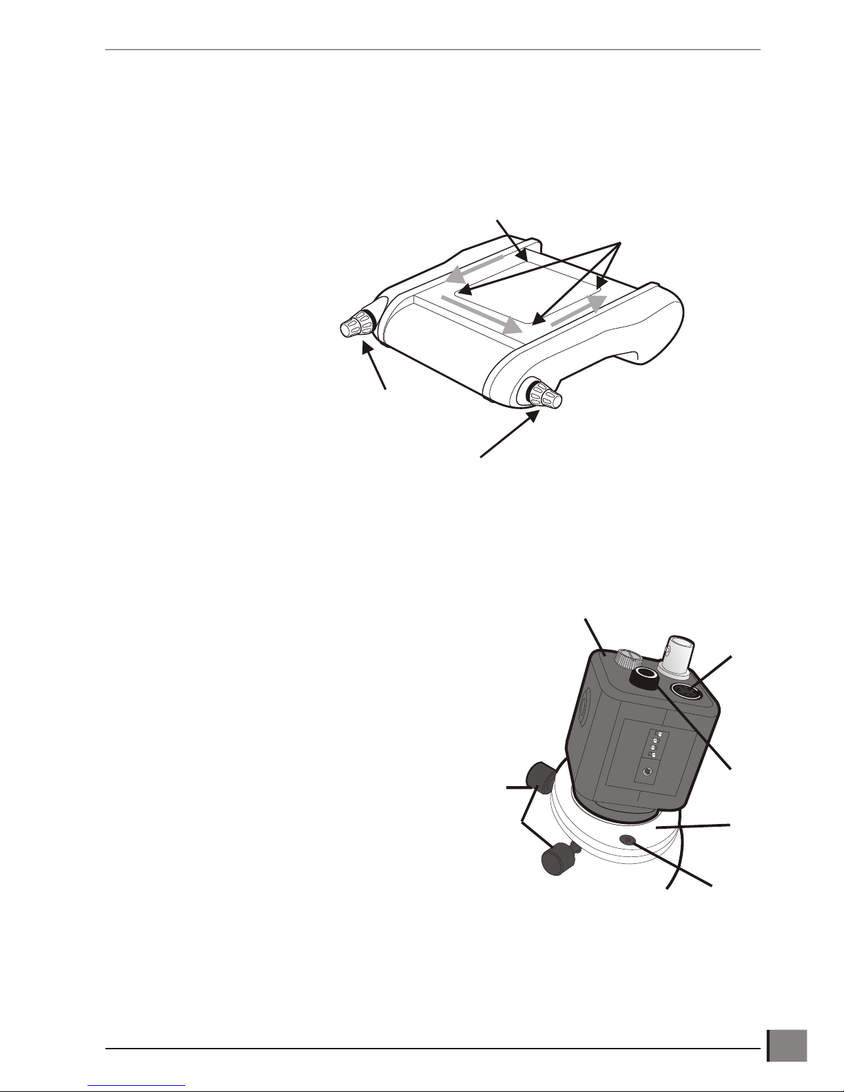
Control box
Icons
The icons on the front panel of the control box symbolise the following:
On/Off switch
Power on indicator
Illuminator intensity control
Ringlight connection point
Refer to manual
HEAD Power for viewing unit (boom mount only)
Controls
The LED ringlight, which can be used with substage
illumination, provides above stage il lu mi na tion and is used
for illuminating sur face fea tures, blind holes, etc.
u Switch the unit on u and adjust intensity by
rotating the dimmer control v.
u The LED illuminator is provided with a temperature
protection system w to ensure long term LED
performance is not compromised by overheating.
u If the temperature protection indicator illuminates,
the power to the LED's will gradually reduce until the temperature
stabilises. If the indicator remains illuminated, remove the illuminator and
ensure neither the air inlet around the objective, nor the fan outlet are obstructed.
LED illuminator specification
The LED illuminator unit has an integral power supply with the following specification:
Input voltage: 110 to 240v ~ 50/60Hz 0.9A max
Fuse rating: 110v 1.0A anti-surge
230v 0.5A anti-surge
The fuse is located in the IEC mains connector on the rear of the control box (see page 13).
Hawk 2 or 3-Axis Manual Non-Contact Measuring System www.visioneng.com/support
OPERATION
22
0
1
v
w
u

Substage
The Substage illumination is used for the accurate measurement of through holes, profiles and edge features etc.
The depth of field is adjusted by rotating the thumbwheel on the Hawk base.
The illumination can be used with spotlight, ringlight and EPI illumination systems.
Adjust light intensity by rotating the dial control on the illumination power supply unit.
Taking a measurement (QC-200)
Select the correct lens for the component being measured, based on the size of the component and field of view
requirements (refer to magnification tables on page 20).
Focus on the component or feature being measured, firstly use the Z axis coarse control and then the fine control until
the component or feature is in focus.
A measurement is made by moving the stage and subject under the cross-line graticule, visible through the
dynascopic viewing head.
Features and dimensions are measured by aligning the cross-line with the desired feature and entering the preset
number of points evenly distributed around the feature.*
A point is measured by aligning the cross-line on a single point.
Lines can be measured by aligning the cross-line at a minimum of two points.
Circles can be measured by aligning the cross-line at a minimum of 3 points on its circumference.
The software will calculate the result based on the points entered and display in the results window. Distances are
calculated by selecting relevant features and selecting the distance function.
The accuracy of the stage movement is achieved by the application of NLEC (Non Linear Error Correction) which
compensates for any mechanical stage errors across the calibrated stage area. The unique NLEC file, relating to the
relevant stage is stored in the Quadra-Chek.
*Further Details on taking measurements can be found in the relevant Quadra-Chek user guide.
www.visioneng.com/support Hawk 2 or 3-Axis Manual Non-Contact Measuring System
OPERATION
23
Thumbwheel

Taking a measurement (QC-300/QC-5000 VED)
Select the correct lens for the component being measured, based on the size of the component and field of view
requirements (refer to magnification tables on page 20).
Focus on the component or feature being measured. Use the Z axis control until the component or feature is in focus.
A measurement is made by moving the stage so that subject or the start of the subject is within the field of view,
dependent on the feature being measured.*
A point is measured by aligning the simple tool on a single point. Lines can be measured by aligning the simple tool
on two points (minimum) on the line. Circles can be measured by aligning the simple tool on three points (minimum)
around the circle. A point can also be measured by selecting the single or multipoint tool on the QC-300 and probing
single or multiple points on selected features.
Features and dimensions are measured by selecting the appropriate QC-5000 video tool, from the toolbar, aligning
the tool over the feature being measured. After performing a simple tool teach the tool is fired and the
predetermined number of points will scan across the tool area and find the edge of the feature.
The software will calculate the result based on the points entered and display in the results window. Distances are
calculated by selecting relevant features and selecting the distance function.
*Further Details on taking measurements can be found in the relevant Quadra-Chek user guide.
Good working practices
When selecting points on features the point should always be approached in the same fashion, e.g. always work
towards a point in the X axis first, moving from left to right and then move towards a point in the Y axis, moving from
top to bottom.
This procedure will increase repeatability. If looking to measure the form of a feature, it is best to take at least eight
points to achieve the most repeatable result.
Note: Contact your local Vision Engineering representative for full details of available training
programs.
Hawk 2 or 3-Axis Manual Non-Contact Measuring System www.visioneng.com/support
OPERATION
24

ROUTINE MAINTENANCE
Routine maintenance is important for the longstanding of the Hawk Measuring System. For more complex
maintenance contact the local Vision Engineering representative.
Graticule adjustment
u Undo the securing clip at the base of the front cover and lift the cover off.
u To focus and centralize each graticule, loosen the appropriate retaining knob and move the graticule up or down
to focus. Re-tighten the retaining knob.
u To adjust the graticules, place a known 90º gauge (slip gauge or crossline) on the stage and focus the image.
Close one eye and locate the crossline on the corner of the gauge by unlocking and adjusting the grubscrews.
Once the image is located, lock the grubscrews with the locking nuts.
u Repeat the procedure using the other eye. Make the adjustment so that the graticules overlay each other.
Note: If the image is uncomfortable to the eyes, repeat the above procedure.
www.visioneng.com/support Hawk 2 or 3-Axis Manual Non-Contact Measuring System
ROUTINE MAINTENANCE
25
Graticules
Gauge
Crossline
Graticule Lock Nuts & Grubscrews
(2 per Graticule)
Retaining Knobs
Securing Clip
WARNING
DISCONNECT THE MAINS POWER SUPPLY BEFORE PERFORMING ANY
MAINTENANCE ROUTINE
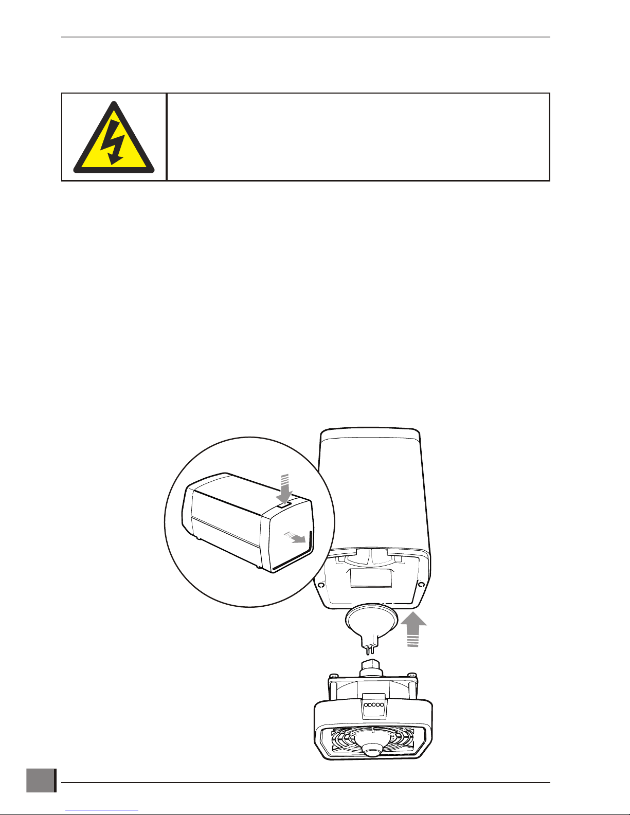
Changing the illuminator lamp
CAUTION: Allow the illuminator to cool down before carrying out this task.
u Press down the lamp/fan assembly release button u.
u Lift out the lamp/fan assembly v.
u Remove the lamp as shown w.
u Insert the replacement lamp and check that it is fully pushed into the lamp holder.
Note: DO NOT touch the base, pins or filament assembly of the new bulb during installation. Oil from
hands can cause premature bulb failure. The bulb should only be held by its reflector.
u Periodically inspect the cooling fan and its vents for debris build-up. The front and rear vents must be clean to
allow adequate airflow. Inadequate airflow will result in increased operating temperatures and reduced bulb life.
The fan should be running whenever power is supplied to the illuminator.
Hawk 2 or 3-Axis Manual Non-Contact Measuring System www.visioneng.com/support
ROUTINE MAINTENANCE
26
WARNING
REMOVE POWER FROM THE SYSTEM BEFORE OPENING THE CASE.
u
v
w

General care
• Cover the Hawk with a dust cover when not in use.
• Remove dust with a soft brush or cleaning cloth.
• The viewing screen and lenses should be cleaned with a lens cleaning cloth.
• Keep accessories in a dust-free environment when not in use.
Consumable and replacement parts
Item Specification
Quantity
in Pack
Part
Number
Substage/Episopic Bulb (Illuminator Bulb) 100w/12v Halogen Lamp 1 LAM-1770
Spotlight Bulb 20w/12v Lamp 1 LAM-1300
Stage Glass 150x150mm 1 201-B0686
Stage Glass 200x150mm 1 184-B0227
Stage Glass 300x225mm 1 159-B0394
Stage Glass 400x300mm 1 159-B0452
Anti-Glare shield Hinged Anti-Glare shield 1 188-A1001/A
100W PSU Fuse 1.6 amp Anti-Surge 1 FUS-0243
100W PSU Fuse 800 ma Anti-Surge 1 FUS-0255
150W PSU Fuse 2.5 amp Anti-Surge 1 FUS-0395
150W PSU Fuse 1.5 amp Anti-Surge 1 FUS-2367
Environmental conditions
Hawk is an accurate, industrial gauging instrument. To achieve the optimum accuracy and repeatability, the following
considerations should be taken into account:
• Po si tion the Hawk on a firm, rigid ta ble.
• Do not position the instrument near any source of vi bra tion.
• Ensure that the illuminator power supplies have sufficient ven ti la tion.
• Do not position the instrument close to a radiator or similar heating sys tem.
• Do not position the instrument in direct sunlight, or where bright reflections will prevent a com fort able viewing
position.
www.visioneng.com/support Hawk 2 or 3-Axis Manual Non-Contact Measuring System
ROUTINE MAINTENANCE
27
ACCESSORIES & OPTIONS
Hawk 2 or 3-Axis Manual Non-Contact Measuring System www.visioneng.com/support
ACCESSORIES & OPTIONS
28
STANDARD
Core Instrument
Head
Assembly H-001
100W/12V Transformer
(EPI)
100V
115V
220V
240V
100W/12V Transformer
100V
115V
220V
240V
Fibre Optic
H-017
Fibre Optic
H-017
100W Illuminator
H-043
PSU
H-044
EPI
H-015/H-016
PSU
H-044
Substage Illuminator
H-043
200mm x 150mm
Manual Precision Stage
H-081
150mm x 150mm
Manual Stage
H-080
Dust Cover
H-200
Photographic
Attachment
H-070
Photographic
Attachment
H-011
Camera Adaptor
(C-mount)
H-074
Canon A620 Adaptor
K-027
Macro
Lenses
10x H-007
20x H-008
50x H-009
100x H-010
Standard Working Distance
Micro Lenses
50x H-110
100x H-100
200x H-101
500x H-103
Long Working Distance
Micro Lenses
100x H-104
200x H-105
500x H-106
1000x H-107
Super Long Working Distance
Micro Lenses
200x H-108
500x H-109
QC 200
2 axis - H-050
3 axis - H-051
QC 300
2-Axis (VED) H-047
3-Axis (VED) H-048
3-Axis H-046
QC 5000
3 axis - H-052
Monitor
H-054
Bench
Stand
H-002
complete with
High Intensity
Substage Illuminator
& Diffuser Kit
x 10
x 20
x 50
x 100
x 100
x 200
x 500
x 50
x 100
x 500
x 200
x 1000
x 200
x 500
LED Ringlight
LED Control Box
H-078
OTHER SOLUTIONS FROM VISION ENGINEERINGVision Engineering manufactures a wide range of stereo inspection and non-contact measuring systems. The
following tables provide a summary of the products utilising Vision's technology. For more information on any of
these products either visit the website or contact the nearest Vision Engineering branch/distributor.
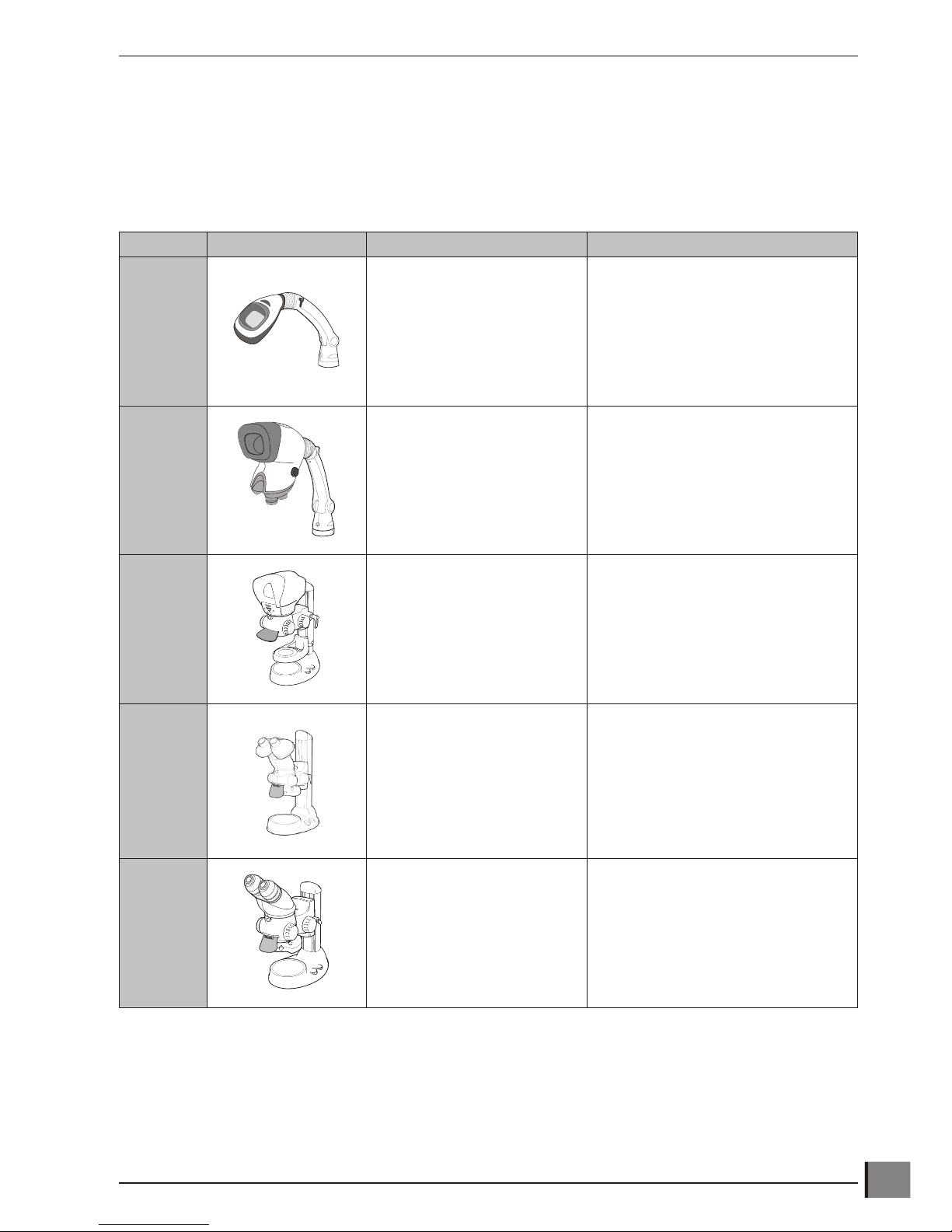
Stereo inspection systems
Product Picture Features Description
Lentis
• 2.5 dioptres
• Multi lay ered anti re flec tive
coated lens
A state of the art bench magnifier for
inspection, manipulation and material
rework.
Mantis
• x2 - x20 Mag ni fi ca tion
• Shadow-free LED cold
il lu mi na tion, both sur face and
substage
• Long work ing dis tances,
large depth of field
The Mantis family is a unique range of
optical systems without eyepieces, for
intricate tasks requiring superb quality
viewing over long periods of use.
Available with universal arm or rigid
bench stand option.
Lynx
• X2.1 - X120 mag ni fi ca tion
• Camera op tion
• Optical viewing head
(re places con ven tional
eye pieces).
Advanced optical system (without
eyepieces) stereo zoom microscope.
Available in boom and rigid stand
configuration with a wide range of
optional accessories (e.g. lighting,
cameras).
Alpha
• x2.1 – x160 mag ni fi ca tion
• Cam era op tion
• Ex panded Pu pil eye pieces
Expanded Pupil eyepiece stereo zoom
microscope. Available in boom and
bench stand configuration with a wide
range of optional accessories (e.g.
lighting, cameras)
Beta
• x2.1 – x160 mag ni fi ca tion
• Cam era op tion
• Con ven tional eye pieces
Conventional eyepiece stereo zoom
microscope. Available in boom and
bench stand configuration with a wide
range of optional accessories (e.g.
lighting, cameras)
www.visioneng.com/support Hawk 2 or 3-Axis Manual Non-Contact Measuring System
29
OTHER SOLUTIONS FROM VISION ENGINEERING
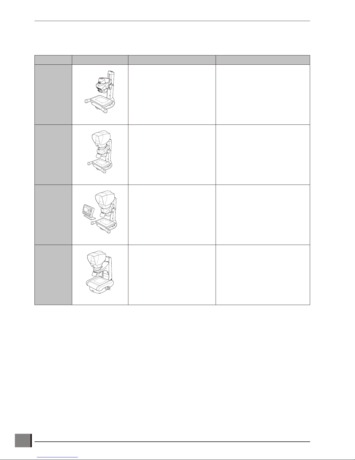
Non-contact measuring systems
Product Picture Features Description
Merlin
• 150mm x 100mm stage
• x10 - x50 mag options
• QC-300 Microprocessor
• Manual/Automatic Video Edge
Detection
2-axis video measuring system with
touch screen video processor.
Powerful yet simple to use, ideal for a
wide range of gauging applications.
Peregrine
• 150mm x 100mm stage
• x10 - x50 mag op tions
• QC-300 Mi cro pro ces sor
• Au to mated video edge de tec tion
2-axis video measuring system with
optical and video measurement
capability. Simple to use, allowing for
quick results every time.
Kestrel
• 150mm x 100mm stage
• x10 - x50 mag options
• QC200 Mi cro pro ces sor
• Op ti cal view ing head
(re places con ven tional
eye piece)
Entry level, 2-axis measuring system.
Ideal for shop floor gauging
applications.
Hawk
automatic
• 200mm x 150mm stage
• x10 - x100 mag options
• Video Edge De tec tion
• Motor ised stage move ment
• 2 or 3 axis ca pa bil ity
Automated measuring system
combining optical viewing head with
PC based Video Edge Detection. 2
and 3 axis motorised stage
movement controlled by QC5000 PC
software.
Hawk 2 or 3-Axis Manual Non-Contact Measuring System www.visioneng.com/support
30
OTHER SOLUTIONS FROM VISION ENGINEERING

SERVICE & CALIBRATION RECORDHawk serial number ________________
Stage serial number ________________
Service type Comments
Date of
service
Date of next
service
Company Signature
SERVICE & CALIBRATION RECORD


WARRANTY
WARRANTY
This product is warranted to be free from defects in material and workmanship for a period of one year from the date of
invoice to the original purchaser.
If during the warranty period the product is found to be defective, it will be repaired or replaced at facilities of Vision
Engineering or elsewhere, all at the option of Vision Engineering. Shipment costs for warranty repairs, to and from Vision
Engineering facilities will not, normally, be borne by Vision Engineering. However, Vision Engineering reserves the right to
refund the purchase price if it is unable to provide replacement, and repair is not commercially practicable or cannot be
timely made. Parts not of Vision Engineering manufacture carry only the warranty of their manufacturer. Expendable
components such as fuses carry no warranty.
This warranty does not cover damage in transit, damage caused by misuse, neglect, or carelessness, or damage resulting
from either improper servicing or modification by other than Vision Engineering approved service personnel. Further, this
warranty does not cover any routine maintenance work on the product described in the user guide or any minor
maintenance work which is reasonably expected to be performed by the purchaser.
No responsibility is assumed for unsatisfactory operating performance due to environmental conditions such as humidity,
dust, corrosive chemicals, deposition of oil or other foreign matter, spillage, or other conditions beyond the control of
Vision Engineering.
Except as stated herein, Vision Engineering makes no other warranties, expressed or implied by law, whether for resale,
fitness for a particular purpose or otherwise. Further, Vision Engineering shall not under any circumstances be liable for
incidental, consequential or other damages.

Distributor
Visit our multi-lingual website:
LIT 1719 R2.1/02/08
www.visioneng.com
For more information...
Vision Engineering has a network of offices and technical distributors around the world. For more information,
please contact your Vision Engineering branch, local authorised distributor, or visit our website.
Vision Engineering Ltd.
(Manufacturing)
Send Road, Send, Woking,
Surrey, GU23 7ER, England
Tel: +44 (0) 1483 248300
Fax: +44 (0) 1483 223297
Email: generalinfo@visioneng.com
Vision Engineering Ltd.
(Commercial)
Monument House, Monument Way West,
Woking, Surrey, GU21 5EN, England
Tel: +44 (0) 1483 248300
Fax: +44 (0) 1483 248301
Email: generalinfo@visioneng.com
Vision Engineering Inc.
(Manufacturing & Commercial)
570 Danbury Road, New Milford,
CT 06776 USA
Tel: +1 (860) 355 3776
Fax: +1 (860) 355 0712
Email: info@visioneng.com
Vision Engineering Inc.
(Commercial West Coast USA)
745 West Taft Avenue, Orange,
CA 92865 USA
Tel: +1 (714) 974 6966
Fax: +1 (714) 974 7266
Email: info@visioneng.com
Vision Engineering Ltd.
(Central Europe)
Anton-Pendele-Str. 3,
D-82275, Emmering, Germany
Tel: +49 (0) 8141 40167-0
Fax: +49 (0) 8141 40167-55
Email: info@visioneng.de
Nippon Vision Engineering
(Japan)
272-2 Saedo-cho, Tsuduki-ku,
Yokohama-shi, 224-0054, Japan
Tel: +81 (0) 45 935 1117
Fax: +81 (0) 45 935 1177
Email: info@visioneng.jp
Vision Engineering Ltd.
(France)
1 Rue de Terre Neuve, ZA Courtaboeuf,
91967 Les Ulis Cedex, France
Tel: +33 (0) 164 46 90 82
Fax: +33 (0) 164 46 31 54
Email: info@visioneng.fr
Vision Engineering Ltd Italia
(Italy)
20092 Cinisello Balsamo MI, Italy
Tel: +39 02 6129 3518
Fax: +39 02 6129 3526
Email: info@visioneng.it
Via Cesare Cantù, 9
Vision Engineering Ltd
(China)
11J, International Ocean Building,
720 Pudong Avenue, Shanghai,
200120, P.R. China
Tel: +86 (0) 21 5036 7556
Fax: +86 (0) 21 5036 7559
Email: info@visioneng.com.cn
Vision Engineering
(India)
Tel: +91 (022) 2613 0699
Fax: +91 (022) 2610 3845
Email: info@visioneng.co.in
 Loading...