

User Guide
Hawk MKII 3-Axis Non-Contact Measurement Systems

INTRODUCTIONHAWK MKII 3-Axis Non-Contact Measurement Systems
Vision Engineering's Hawk family of 3-axis non-contact measuring systems are designed to achieve the highest levels
of accuracy and repeatability. With high precision measuring stages, and a range of illumination options to suit all
applications.
Health & Safety
Vision Engineering and its products conforms to the requirements of the EC Directives on Waste Electrical and
Electronic Equipment (WEEE) and Restriction of Hazardous Substances (RoHS).
EN61326-1:2006
FCC Part 15
EN61010-1:2010
WARNING: ALL EQUIPMENT PLUGGED INTO THIS UNIT MUST BE APPROVED TO EN60950-1:2001 AND
CHECK CURRENT RATING OF OUTPUT SOCKET IF USED.
HAWK EQUIPMENT – WARNING
This warning refers to CNC systems
Warning – hazardous moving parts.
To avoid entrapment, keep fingers and other body parts
away from moving parts
To stop all CNC movement in an emergency situation move the joystick in ANY direction.
This will interrupt the CNC programme and stop any movement.
In the case of a system failure or crash, to stop the CNC movement switch the Control Power Supply off or switch off
the mains power to the system.
WARNING
DISCONNECT THE MAINS POWER SUPPLY BEFORE PERFORMING ANY
MAINTENANCE ROUTINE
UNPACKING
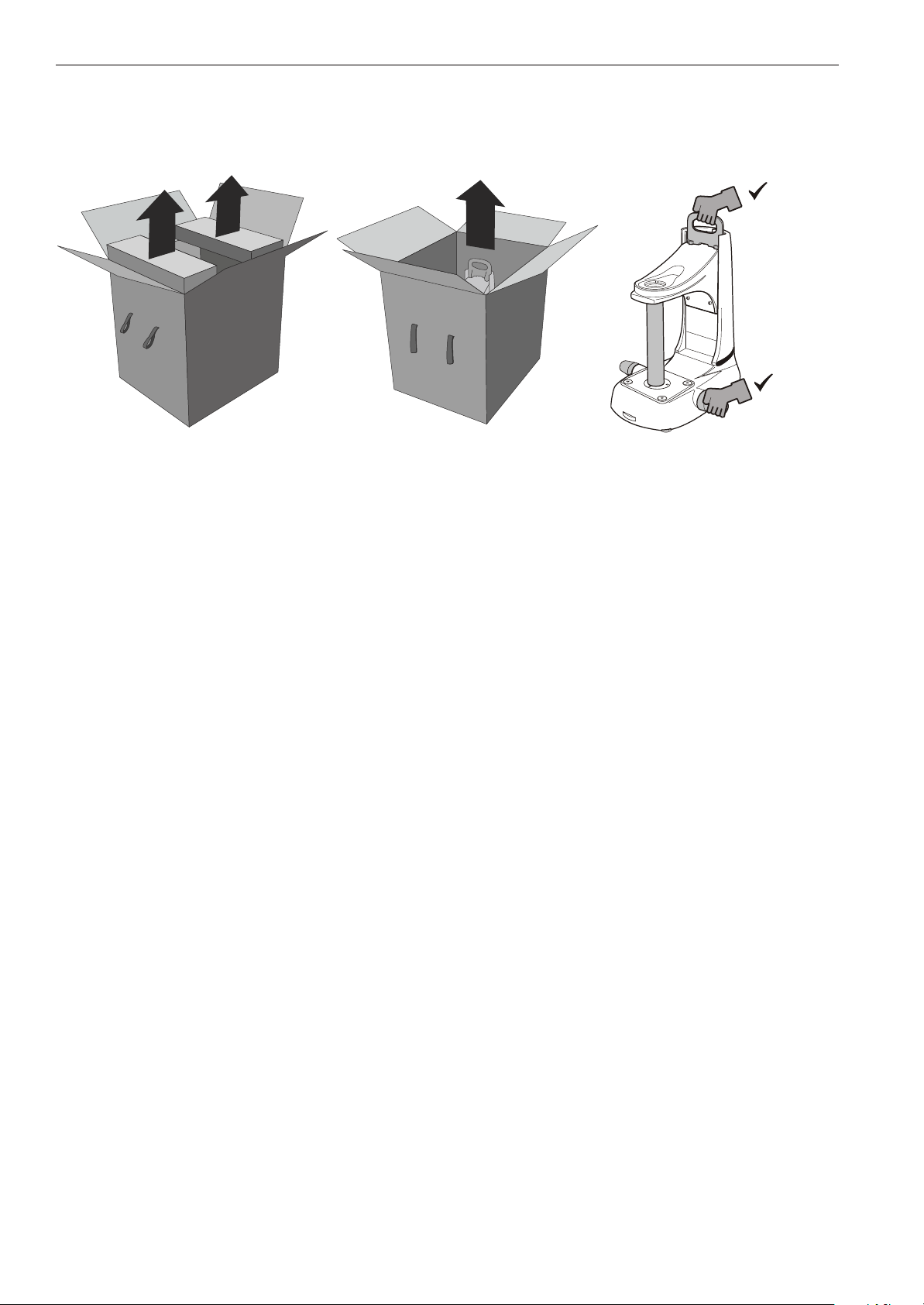
UNPACKINGUnpacking the Hawk stand (all systems)
1
2
Hawk with M3 software manual system
Box 1 Stand
Box 2 Head
Box 3 PSU - Manual and lighting, and cables
Box 4 M3 software pre-installed PC, keyboard and mouse
Box 5 Monitor
Box 6 M3 USB interface box
Box 7 Manual stage (200mm x 150mm)
Box 8 Optional accessories
3
Hawk with M3-CNC software motorised system
Box 1 Stand
Box 2 Head
Box 3 PSU CNC, and cables
Box 4 Joystick
Box 5 Trackerball
Box 6 M3-CNC software pre-installed PC, keyboard, mouse
Box 7 Monitor
Box 8 M3-CNC USB interface box
Box 9 Motorised stage (200mm x 150mm)
Box 10 Optional accessories
Hawk QC-5000 manual system
Box 1 Stand
Box 2 Head
Box 3 PSU CNC, and cables
Box 4 Joystick
Box 5 Trackerball
Box 6 QC-5000 PC, keyboard and mouse
Box 7 Monitor
Box 8 Manual stage (150mm x 150mm or 200mm x 150mm)
Box 9 Optional accessories
Hawk QC-5000 motorised system
Box 1 Stand
Box 2 Head
Box 3 PSU CNC, and cables
Box 4 Joystick
Box 5 Trackerball
Box 6 QC-5000 PC, keyboard and mouse
Box 7 Monitor
Box 8 Motorised stage (200mm x 150mm)
Box 9 Optional accessories

CONTENTS
CONTENTSPACKING CONTENTS
Head pack 1
Stand pack 1
Stage pack 1
Control units 2
CNC control PSU 2
Joystick and trackerball 2
Control PSU manual and lighting control 2
Accessories 3
Macro 3
Micro 3
M3 USB Interface box 4
QC-5000 PC 4
ASSEMBLY
Removing the transit protection 5
Attaching the stage 5
Ringlight attachment 6
Macro EPI attachment 6
Macro EPI and ringlight attachment 7
Micro EPI and lens turret attachment 7
Attaching the head only 8
Mounting camera to rear 8
Attaching Unicam II 9
Attaching the anti-glare shield 9
Inserting the stage glass 10
Cable connection M3-VED (manual systems) 11
Cable connection M3-CNC (CNC systems) 12
Cable connection QC-5000 (manual systems) 13
Cable connection QC-5000 (CNC systems) 14
START UP / SHUT DOWN PROCEDURE
CNC start up procedure (PC / M3) 15
CNC shutdown procedure (PC /M3) 15
Manual lighting control PSU start up 15
Manual lighting control PSU shutdown 15
SETTING UP
Manual system controls 16
CNC system controls 17
Align head to stage 18
Stand levelling 18
Stage glass levelling 18
Camera Setup 18

CONTENTS
OPERATION
Objective lens 19
Episcopic illuminator 20
Symbols and icons 20
Manual and lighting controls 21
Ringlight control 22
Substage 23
ROUTINE MAINTENANCE
Graticule adjustment 24
Substage LED replacement 25
Episcopic LED replacement 25
General care 26
Consumable and replacement parts 26
Environmental conditions 26
ACCESSORIES & OPTIONS
SERVICE & CALIBRATION RECORD
WARRANTY
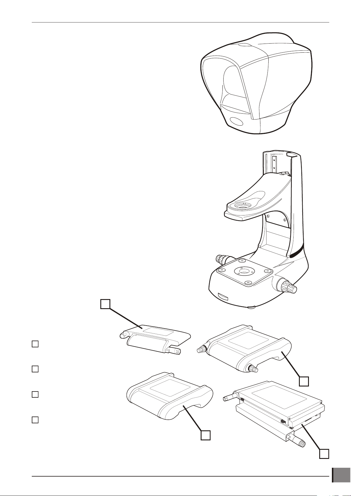
PACKING CONTENTSSee packing list to clarify contents of delivery.
1
2
1
2
3
3
4
4
Head pack
Stand pack
PACKING CONTENTS
Stage pack
150mm x 150mm
(manual)
200mm x 150mm
(manual)
200mm x 150mm
(motorised)
250mm X 150mm
(manual)
www.visioneng.com/support HAWK MKII 3-Axis Non-Contact Measurement Systems
1
PACKING CONTENTS
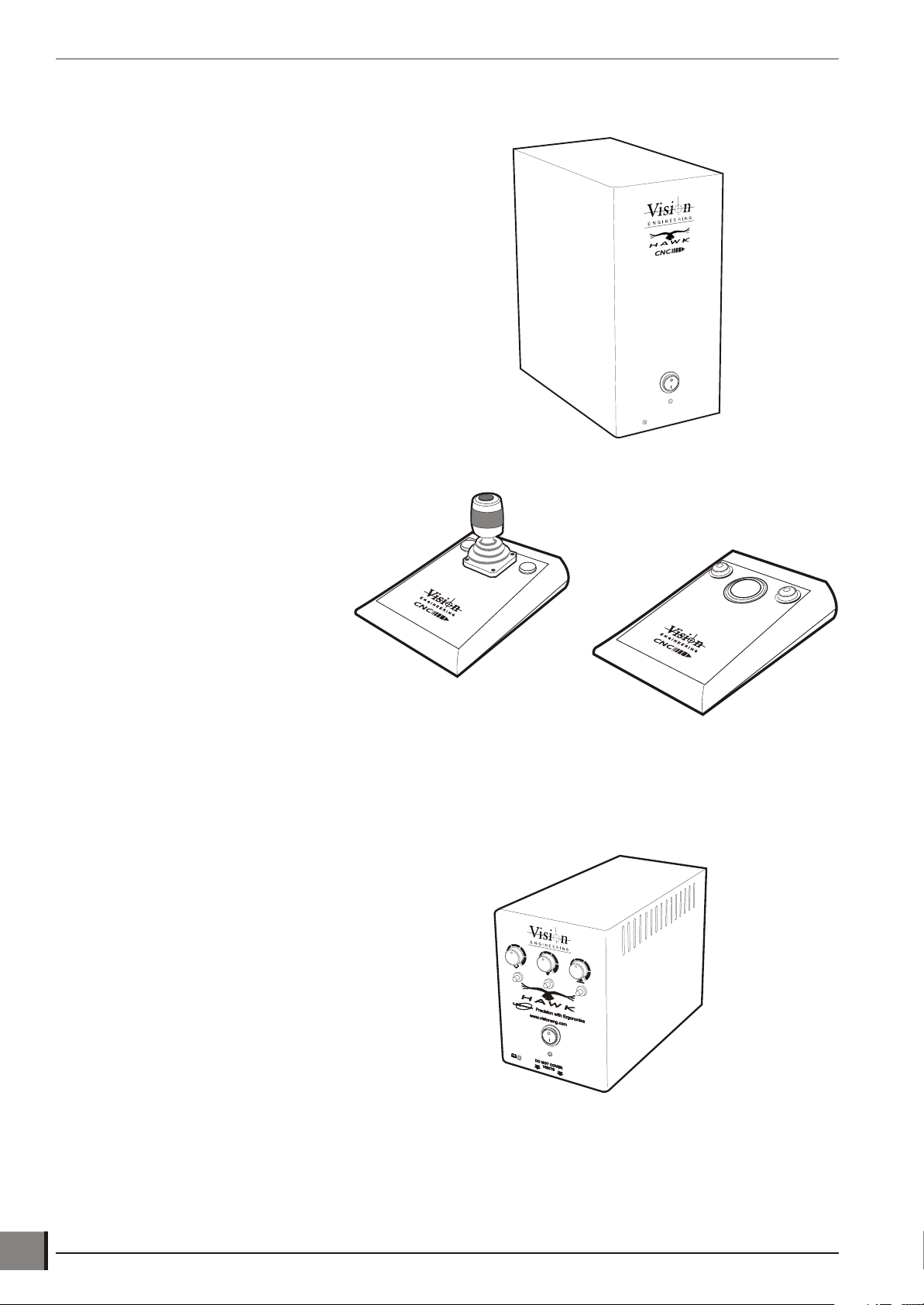
Control units
CNC control PSU
Joystick and trackerball
Control PSU manual and lighting control
2
HAWK MKII 3-Axis Non-Contact Measurement Systems www.visioneng.com/support

Accessories
Macro Micro
PACKING CONTENTS
Substage condenser lens
Object lenses Object lenses
Macro Lens Options
Macro Episcopic
LED illuminator
x1
x2
x5
x10
Substage condenser lens
Micro Lens Options
Micro Micro LWD Micro SLWD
x5 x10 x20
x10 x20 x50
x20 x50
x50 x100
Micro Episcopic
LED illuminator
Camera adaptor
Unicam II
Ringlight illuminator
www.visioneng.com/support HAWK MKII 3-Axis Non-Contact Measurement Systems
3
PACKING CONTENTS
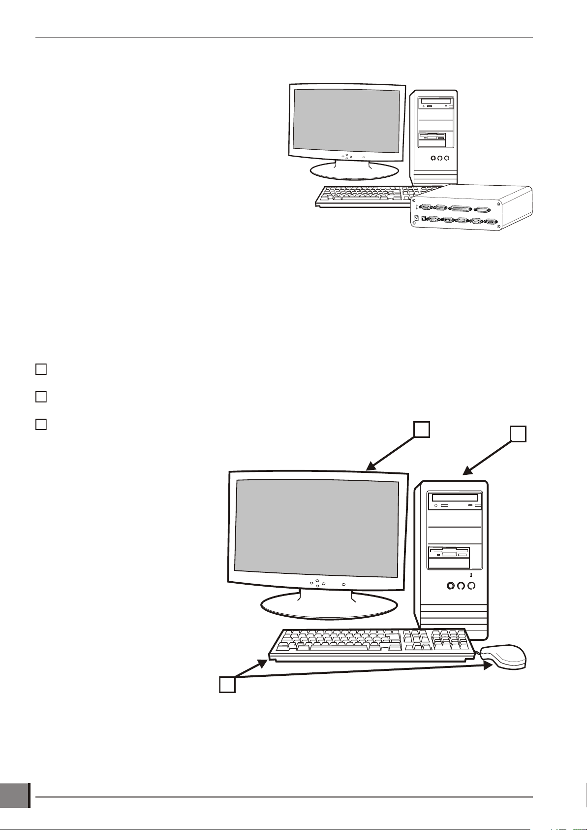
213
123
M3 USB Interface box
M3 USB interface unit
Note: Please ensure your Windows® operating
system is kept up to date through
Windows® Update.
Note: In applications where the USB
signal/power is weak (i.e. with long leads
and some laptops) we recommend using a
powered hub or repeater cable (available
from your local PC retailer).
QC-5000 PC
QC-5000 PC
Monitor
Keyboard and mouse
Note: Please ensure your Windows®
operating system is kept up to date
through Windows® Update.
4
HAWK MKII 3-Axis Non-Contact Measurement Systems www.visioneng.com/support
ASSEMBLY
Micro
Macro
Column
Stage Assembly
Logo
B4
B3B1
B2
ASSEMBLYThe following paragraphs provide instructions on how to assemble the Hawk Measuring System. In most instances
the illustrations are self explanatory; where necessary the illustrations are supported by text.
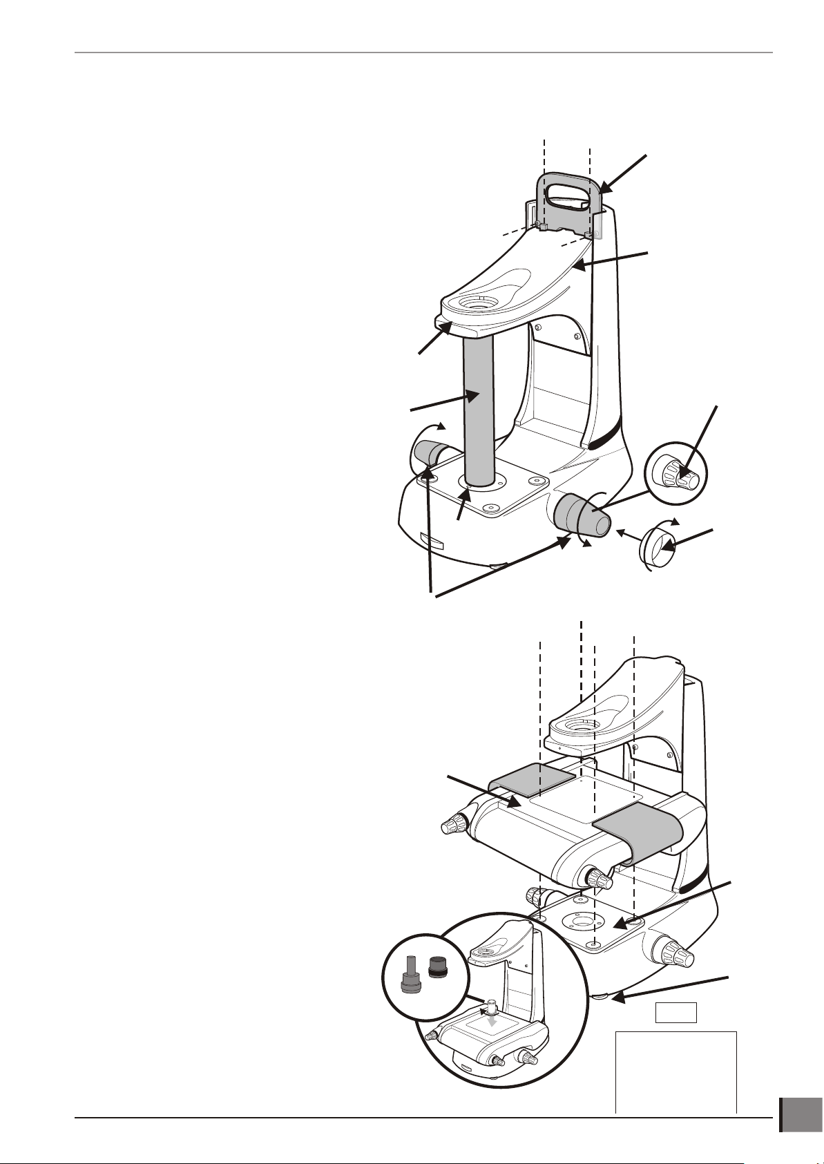
Removing the transit protection
u Use the red transit handle u and either of the focus control covers v
to lift the stand into the required work position.
u Remove the red transit handle and focus control
covers. Screw the two focus control collars w
(one each side) into position.
u Remove the transit handle by removing the
screws that secure it to the stand.
x
u Loosen screws x and y. Use the focus
controls z to raise the head platform {
until there is sufficient room to remove the
transit tube |. Unscrew dovetail from
item | as required.
|
y
u
{
z
w
v
Attaching the stage
u Check the stand base plate u and the underside of the 200mm x
150mm stage v are clean and free of any debris.
u Using the red stage transit handles w, lift the stage into position and
secure it using the bolts provided with the stand, not the bolts that
secure the stage into the transit box.
v
u Use the Allen key supplied to progressively tighten all 4
screws x in the numbered sequence (shown in the
diagram y below) to a torque of 2.8Nm. This is
approximately equal to bolt touch down, plus a quarter
of a turn.
u Remove the stage transit handles.
u Adjust the stabilizing foot z to support
the stand base.
{
w
x
x
x
x
w
u
z
u Screw the required condenser lens {
through the stage and into the stand.
Note: Micro condensers should only be used
with micro lenses when viewing a subject at
stage glass level.
www.visioneng.com/support HAWK MKII 3-Axis Non-Contact Measurement Systems
y
5
ASSEMBLY
Ringlight attachment
Securing Screw
3G Ringlight adapter
Securing Screw
Macro EPI attachment
Note: The same procedure is used to fit either the Macro EPI (illustrated) or the Micro EPI. The Micro
EPI cannot have an Objective Holder or Ringlight fitted.
Grub Screw
Grub Screw
6
HAWK MKII 3-Axis Non-Contact Measurement Systems www.visioneng.com/support

Macro EPI and ringlight attachment
Grub Screw
ASSEMBLY
Grub Screw
Securing Screw
Securing Screw
Micro EPI and lens turret attachment
Grub Screw
Grub Screw
www.visioneng.com/support HAWK MKII 3-Axis Non-Contact Measurement Systems
7

ASSEMBLY
Head
Connector
Head
Socket
Grub
Screw
Camera
Attachment
Grub
Screws
Locking
Plate
Camera
Adapter
Attaching the head only
Mounting camera to rear
u Position camera attachment between the
viewing head and its arm.
u Secure with the grub screws.
u Attach the adapter to the camera
and tighten 3 x grub screws if not
already fitted.
u Locate camera and adapter to the locking
plate (the locking plate must not be
overtight, but enough to hold).
8
HAWK MKII 3-Axis Non-Contact Measurement Systems www.visioneng.com/support

Attaching Unicam II
Unicam
Securing
Screws
Head
Power
Lead
ASSEMBLY
Attaching the anti-glare shield
CAUTION: The Anti-Glare Shield is made of plastic and
must not be over tightened.
Screws
www.visioneng.com/support HAWK MKII 3-Axis Non-Contact Measurement Systems
9

ASSEMBLY
P
O
Inserting the stage glass
Note: The stage glass must be handled with care to avoid any fingerprint marks.
u Align the glass with it's bevelled edges against the
springs (see table below for spring location and
diagram u for the correct orientation of
the stage glass).
u Check that the stage glass is in contact with
all four supports.
u To level the stage glass, refer to page 18.
Stage size Spring location
150 x 150mm Left & Back
200 x 150mm Left & Front
u
10
HAWK MKII 3-Axis Non-Contact Measurement Systems www.visioneng.com/support

ASSEMBLY
RINGLIGHT
EPI
HEAD
VREF
DISPLAY I/O
X Y Z
MAINS POWER IN
MAINS POWER IN
PC USB
KEY
Mains Power
Lighting/Power
X, Y and Z
PC USB
All connectors must be engaged fully and secured with the screws.
Note: In applications where the USB signal/power is weak (i.e. with long leads and some laptops) we
recommend using a powered hub or repeater cable (available from your local PC retailer).
Note: Please ensure your Windows® operating system is kept up to date through Windows® Update.
Cable connection M3-VED (manual systems)
WARNING:To comply with safety regulations, easy access to the mains socket must be maintained.
www.visioneng.com/support HAWK MKII 3-Axis Non-Contact Measurement Systems
11

ASSEMBLY
KEY
Mains Power
USB
Display
Lighting/Power
X, Y and Z
CNC
MAINS POWER IN
Note: In applications where the USB signal/power is weak (i.e. with long leads and some laptops) we
Note: Please ensure your Windows® operating system is kept up to date through Windows® Update.
Cable connection M3-CNC (CNC systems)
All connectors must be engaged fully and secured with the screws.
recommend using a powered hub or repeater cable (available from your local PC retailer).
WARNING:To comply with safety regulations, easy access to the mains socket must be maintained.
12
HAWK MKII 3-Axis Non-Contact Measurement Systems www.visioneng.com/support

ASSEMBLY
RINGLIGHT
EPI
CAMERA
Input
110-240V 50-60Hz
HEAD
Fuse
T1.0AH 240V
T2.0AH 110V
VREF
DISPLAY I/O
SUB-STAGE ILLUMINATION
DISPLAY I/O
Y XZ
PC
(rear)
USB
KEY
Mains Power
USB
Display
Lighting/Power
X, Y and Z
MAINS POWER IN
All connectors must be engaged fully and secured with the screws.
Note: In applications where the USB signal/power is weak (i.e. with long leads and some laptops) we
recommend using a powered hub or repeater cable (available from your local PC retailer).
Note: Please ensure your Windows® operating system is kept up to date through Windows® Update.
Cable connection QC-5000 (manual systems)
WARNING:To comply with safety regulations, easy access to the mains socket must be maintained.
www.visioneng.com/support HAWK MKII 3-Axis Non-Contact Measurement Systems
13

ASSEMBLY
JJOOYYSSTTIICCKK
VREFVREF
CCNNCC
DISPLAY I/ODISPLAY I/O
Z-AXIS MOTOR Z-AXIS MOTOR Y-AXIS MOTOR Y-AXIS MOTOR X-AXIS MOTOR X-AXIS MOTOR
RINGLIGHT
EPI
JOYSTICK
TRACKERBALL
CAMERA
DISPLAY I/O
Y XZ
PC
(rear)
USB
CNC
KEY
Mains Power
USB
Display
Lighting/Power
X, Y and Z
CNC
MAINS POWER IN
All connectors must be engaged fully and secured with the screws.
Note: In applications where the USB signal/power is weak (i.e. with long leads and some laptops) we
recommend using a powered hub or repeater cable (available from your local PC retailer).
Note: Please ensure your Windows® operating system is kept up to date through Windows® Update.
Cable connection QC-5000 (CNC systems)
WARNING:To comply with safety regulations, easy access to the mains socket must be maintained.
14
HAWK MKII 3-Axis Non-Contact Measurement Systems www.visioneng.com/support

START UP / SHUT DOWN PROCEDURE
START UP / SHUT DOWN PROCEDUREWARNING: ENSURE THE RELEVANT START UP AND SHUT DOWN PROCEDURES ARE ALWAYS FOLLOWED
TO AVOID DAMAGE TO SYSTEM.
CNC start up procedure (PC / M3)
Before the PC/M3 or Hawk power supply unit is switched on:
u Plug in all the cable connections and accessories to the HAWK microscope system.
(see appropriate connection diagrams – pages X, Y, Z).
u Turn on PC, or PC and M3 interface box.
u Turn on the HAWK PSU, (NEVER disconnect cables while the unit is switched on).
u Start up the measurement software.
u The system is now ready for use.
CNC shutdown procedure (PC /M3)
When you are ready to shut down:
u Close down the measurement software.
u Turn off the HAWK PSU.
u Shut down the PC or PC and M3 interface box.
u The System is now off and the cables may be safely disconnected if required.
Manual lighting control PSU start up
Before anything is switched on:
u Plug in all the cable connections and accessories to the HAWK microscope system.
(see appropriate connection diagrams – pages X, Y, Z).
u Turn on PC or PC and M3 interface box.
u Turn on the Manual lighting control PSU, (NEVER disconnect cables while the unit is switched on).
u Start up measurement software (if applicable).
u System is now ready for use.
Manual lighting control PSU shutdown
u Close down the measurement software (if applicable).
u Turn off the Hawk PSU.
u Shut down the PC or PC and M3 interface box (if applicable).
The System is now off and the cables may be safely disconnected if required.
www.visioneng.com/support HAWK MKII 3-Axis Non-Contact Measurement Systems
15

SETTING UP
Fine
Focus
Control
Illumination
Power Supply
Illumination
Controls
Coarse
Focus
Control
Y Axis
Control
ON/OFF
Switch
X Axis
Control
Substage
Iris Control
Levelling
Foot
Objective Lens Macro - Open Iris - decrease depth of field
- Close Iris - increase depth of field
SETTING UPManual system controls
Turn on the illuminator power supplies and check that the LED at the centre of the head is illuminated.
The manual system controls are identified below.
16
HAWK MKII 3-Axis Non-Contact Measurement Systems www.visioneng.com/support

CNC system controls
Z
X
Y
ON/OFF
Switch
Substage
Iris Control
Levelling
Foot
Objective Lens Macro - Open Iris - decrease depth of field
- Close Iris - increase depth of field
X
Y
SETTING UP
Default Joystick button functions:
u = Enter
v = Speed Toggle
w = Finish
Default Trackerball button functions:
v = Speed Toggle
w = Finish
u
v
w
v
w
www.visioneng.com/support HAWK MKII 3-Axis Non-Contact Measurement Systems
17

SETTING UP
X Axis
Control
Fixed
Corner
Adjustable
Glass Supports
Y Axis
Control
Align head to stage
u Ensure that an objective lens is fitted.
u Ensure the head is switched on and then loosen it using an hexagonal/Allen key.
u Align the front edge of the gauge block (or straight edge) with the front edge of the stage glass.
u Rotate the head until the horizontal cross line is parallel with the rear edge of the gauge block (or straight edge).
u Lock the head in position with the hexagonal/Allen key.
Stand levelling
u Adjust the levelling foot until the stand is stable.
Stage glass levelling
u Adjust the X and Y axis controls to bring the rear left-hand
corner of the stage glass (fixed corner) into view.
u Adjust the coarse/fine focus control to bring the
glass surface into sharp focus.
u Adjust the X and Y axis controls to
bring the front left-hand corner
into view.
u Use the relevant adjustable glass
support to bring the surface of the
glass into sharp focus.
u Repeat the above procedure for the
remaining two corners.
Camera Setup
u Loosen hexagonal headed screws u on locking plate v and continue to turn
camera w until it is in the correct position.
u Connect the camera to the PC and power supply as required.
w
u Bring the target/slip into focus within the head, as centrally aligned to
crosshair as possible.
u Match the view on the monitor with that in the head - move the
camera by using the thumbscrews x.
u Tighten the hexagonal headed screws on the locking plate to hold
camera in position.
x
18
HAWK MKII 3-Axis Non-Contact Measurement Systems www.visioneng.com/support
v
u

OPERATION
OPERATIONWARNING: ENSURE THE RELEVANT START UP AND SHUT DOWN PROCEDURES ARE ALWAYS FOLLOWED
TO AVOID DAMAGE TO SYSTEM (SEE PAGE 15).
To achieve the optimum results from the Hawk Measuring System, the illumination and optics need to be adjusted to
provide the best possible image to the operator. Certain lighting options are better for some applications than others.
Illumination and focus should be adjusted until the image is clear and bright, with good contrast. Maximum contrast
gives the best image resolution and allows for the highest level of accuracy and repeatability.
Contact the nearest Vision Engineering branch/distributor for further advice.
Objective lens
Iris control
Each Macro objective lens has an adjustable iris which restricts the aperture of the lens. By rotating the control ring
on the bottom of the objective lens, the iris opens and closes. Adjusting the objective lens aperture slightly increases
or decreases the depth of field. This feature is useful for subjects where greater surface definition is required. The
same results can be achieved with a Micro objective lens by adjusting the iris wheel in the Episcopic illuminator.
Closing the Substage Iris improves ability to locate an edge on a cylindrical component/raised profile.
Magnification tables
Macro Lenses
Part No. Objective Lens Total Magnification Working Distance
H-007 x1 10x 84mm 14.2mm 270µm
H-008 x2 20x 81mm 7.1mm 67µm
H-009 x5 50x 61mm 2.8mm 10µm
H-010 x10 100x 35mm 1.4mm 6µm
Standard Working Distance Micro Lenses
Part No. Objective Lens Total Magnification Working Distance
H-110 x5 50x 20.0mm 4.4mm 12.22µm
H-100 x10 100x 10.1mm 2.2mm 3.06µm
H-101 x20 200x 3.1mm 1.1mm 1.3µm
H-103 x50 500x 0.66mm 0.44mm 0.3µm
Long Working Distance Micro Lenses
Part No. Objective Lens Total Magnification Working Distance
H-104 x10 100x 21.0mm 2.2mm 4.4µm
H-105 x20 200x 12.0mm 1.1mm 1.72µm
H-106 x50 500x 10.6mm 0.44mm 1.10µm
H-107 x100 1000x 3.4mm 0.22mm 0.43µm
Field of View
(diameter)
Field of View
(diameter)
Field of View
(diameter)
Depth of Field
Depth of Field
Depth of Field
Super Long Working Distance Micro Lenses
Part No. Objective Lens Total Magnification Working Distance
H-108 x20 200x 21.0mm 1.1mm 2.24µm
H-109 x50 500x 15.0mm 0.44mm 1.36µm
Field of View
(diameter)
Depth of Field
www.visioneng.com/support HAWK MKII 3-Axis Non-Contact Measurement Systems
19

OPERATION
Control Lever
LED EPI
Thumbwheel
Episcopic illuminator
The Episcopic illuminator provides through the lens illumination for measuring deep surface features, holes and blind
bores. The light follows the optical path through the objective lens. The following adjustment can be made:
• Ad just the sur face light ing to suit the com po nent by us ing the thumbwheel and the beam split mir ror.
• Adjust light in ten sity.
• Adjust the depth of field of the objective lens by rotating the iris control thumbwheel (a smaller iris increases
the depth of field).
• To change the image con trast, fully engage the beam split mirror control lever.
Symbols and icons
Key to symbols and icons
The symbols and Icons below are shown where applicable:
Ringlight
Sub-stage
Episcopic illumination
Display I/O Connection to PC or M3 interface box
Refer to manual
HEAD Viewing Head power
VREF Video reference
CNC Connection to PC or M3 interface box
JOYSTICK Connection to Joystick controller
X,Y, Z AXIS
MOTOR Connection to the HAWK motor connections
20
HAWK MKII 3-Axis Non-Contact Measurement Systems www.visioneng.com/support

OPERATION
Manual and lighting controls
Lighting is controlled by toggle switch and dimmer knob in Manual mode. Note that the manual lighting controls will
not operate the lighting if the PC lighting control cable is connected to the ‘Display I/O’ port at the back of the unit.
Ringlight illumination
Dimmer Knob
Illumination
ON/OFF switches
Sub stage
illumination
Ringlight status LED
Episcopic illumination
Mains On/Off
Power LED
www.visioneng.com/support HAWK MKII 3-Axis Non-Contact Measurement Systems
21

OPERATION
Ringlight control
The LED Ringlight, which can be used with Sub-stage illumination, provides above stage illumination and is used for
illuminating surface features, blind holes, etc.
u Switch the unit on and adjust intensity as required (QC or PC software).
u The LED illuminator is provided with a temperature protection system to ensure long term LED performance is not
compromised by overheating.
u The Ring light status LED u operates as follows:
Solid Green: The controller is fully operational
Off: The LED Ringlight is not connected
Flashing Green/Amber: The unit is in thermal protection mode, the LEDs will gradually reduce until the temperature
stabilises. Once stabilised the LED will return to green but the maximum brightness level will remain limited, protecting
the Ringlight, until the unit is switched off. If the status persists, remove the illuminator and ensure neither the air inlets
nor the fan outlet are obstructed. If operating the Ringlight under PC control changing the quadrant status will return
the Ringlight to full brightness, ensuring sufficient light under all options.
Solid Red: The unit is in thermal shutdown mode to protect the life of the LEDs. The LEDs have reached a critical
temperature and the controller is unable to stabilise them. The unit will remain in shutdown until a safe
temperature is reached, at this point it will return to normal operation (indicated by the status LED being green).
If the problem persists allow the Ringlight to cool down, remove the illuminator and ensure neither the air inlets
nor the fan outlet are obstructed. If the problem cannot be resolved please contact your nearest representative
(see back page).
u In the above Solid Red condition, remove the illuminator and ensure neither the air inlet v around the
objective, nor the fan outlet w are obstructed.
w
u
v
22
HAWK MKII 3-Axis Non-Contact Measurement Systems www.visioneng.com/support
v

The Ringlight illuminator is used as follows:
Thumbwheel
u
Á
• To il lu mi nate op ti cally dif fi cult sur faces/sur face
• For use with Macro ob jec tive lenses.
• The Ringlight gives a shadow free im age.
• Can be used with Episcopic and Substage il lu mi na tion.
u To adjust the light intensity rotate the dial control on the control box (see page 21).
u To diffuse the light, move the diffuser control u to position À for diffused light or to position Á for no diffusion.
À
fea tures.
Substage
The Substage illumination is used for the accurate measurement of
through holes, profiles and edge features etc. The depth of field is
adjusted by rotating the thumbwheel on the Hawk base.
The illumination can be used with spotlight, ringlight and
EPI illumination systems.
Adjust light intensity by rotating the dial control on the
illumination power supply unit.
Best practice
To ensure the most accurate measurements are taken it is recommended that during the measurement process these
following guidelines are followed:
• When se lect ing points on fea tures the point should al ways be ap proached in the same fash ion, e.g. al ways
work to ward a point on the X axis first, mov ing from left to right and then move to wards a point in the Y axis,
mov ing from top to bot tom. This pro ce dure will in crease re peat abil ity.
• If looking to measure the form of a feature, it is best to take at least eight points to achieve the most
repeatable re sult.
• En sure fans exhaust areas are not blocked or ob structed.
• Do not lean on or shake the upper arm of your Hawk product.
Note: Contact your local Vision Engineering representative for full details of available training
programs.
Note: To achieve the very best from your Hawk non-contact measuring system, you should carry out
regular routine maintenance as well as undertaking a schedule of service and calibration (see
service and calibration record, at the end of this user guide).
www.visioneng.com/support HAWK MKII 3-Axis Non-Contact Measurement Systems
23

ROUTINE MAINTENANCE
Graticules
Gauge
Crossline
Graticule Lock Nuts & Grubscrews
(2 per Graticule)
Retaining Knobs
Securing Clip
WARNING
DISCONNECT THE MAINS POWER SUPPLY BEFORE PERFORMING ANY
MAINTENANCE ROUTINE
Routine maintenance is important for the longstanding of the Hawk Measuring System. For more complex
ROUTINE MAINTENANCE
maintenance contact the local Vision Engineering representative.
Graticule adjustment
u Undo the securing clip at the base of the front cover and lift the cover off.
u To focus and centralize each graticule, loosen the appropriate retaining knob and move the graticule up or down
to focus. Re-tighten the retaining knob.
u To adjust the graticules, place a known 90º gauge (slip gauge or crossline) on the stage and focus the image.
Close one eye and locate the crossline on the corner of the gauge by unlocking and adjusting the grubscrews.
Once the image is located, lock the grubscrews with the locking nuts.
u Repeat the procedure using the other eye. Make the adjustment so that the graticules overlay each other.
Note: If the image is uncomfortable to the eyes, repeat the above procedure.
24
HAWK MKII 3-Axis Non-Contact Measurement Systems www.visioneng.com/support

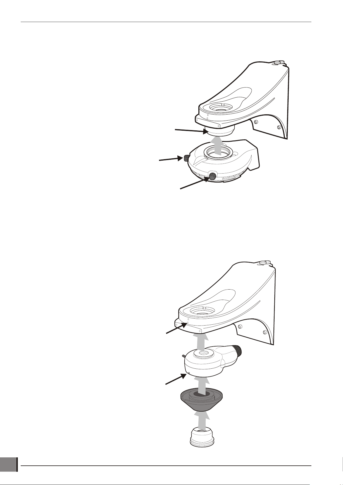
Substage LED replacement
u Take off the substage LED cover plate u by
removing its 3 securing screws.
u Pull out and separate the LED
connector v.
ROUTINE MAINTENANCE
w
u Loosen the 2 grub screws w that
secure the LED assemby x and remove it.
u The replacement procedure is the reversal of
the above.
Episcopic LED replacement
u Remove the episcopic assembly u from the
Hawk and carefully place it on a workbench
as shown.
u Pull its power lead v clear of the socket.
u Loosen the 2 securing screws w and pull
the LED assembly x clear of the
illuminator.
x
u
v
u
w
v
u The replacement procedure is the reversal
of the above.
x
www.visioneng.com/support HAWK MKII 3-Axis Non-Contact Measurement Systems
25

ROUTINE MAINTENANCE
General care
• Cover the Hawk with a dust cover when not in use.
• Remove dust with a soft brush or cleaning cloth.
• The viewing screen and lenses should be cleaned with a lens cleaning cloth.
• Keep accessories in a dust-free environment when not in use.
Consumable and replacement parts
Item Specification
Stage Glass 150x150mm 1 201-B0686
Stage Glass 200x150mm 1 184-B0227
Stage Glass 250x150mm 1 H-161
Anti-Glare shield Hinged Anti-Glare shield 1 188-A1001/D
Substage Illuminator LED LED and heat sink assembly 1 2011095
Episcopic Illuminator LED LED and heat sink assembly 1 2011096
Control PSU CNC T2.0AH 240V 1 FUS4662
Control PSU CNC T4.0AH 110V 1 FUS4853
Control PSU Manual T1.6AH 240V 1 FUS4752
Control PSU Manual T3.15AH 110V 1 FUS4637
Ringlight LED array 8 point LED 1 FUS4662
Ringlight Fan assembly Fan 1 2050307
Quantity
in Pack
Part
Number
Environmental conditions
Hawk is an accurate, industrial gauging instrument. To achieve the optimum accuracy and repeatability, the following
considerations should be taken into account:
• Po si tion the Hawk on a firm, rigid ta ble.
• Do not position the instrument near any source of vi bra tion.
• Ensure that the illuminator power supplies have sufficient ven ti la tion.
• Do not position the instrument close to a radiator or similar heating sys tem.
• Do not position the instrument in direct sunlight, or where bright reflections will prevent a com fort able viewing
position.
26
HAWK MKII 3-Axis Non-Contact Measurement Systems www.visioneng.com/support

ACCESSORIES & OPTIONS
Hawk Stand
200mm x 150mm
Precision Measuring Stage
H-082
OR
OR
QC-5000 PC
QC-5000 PC
Key
Mandatory Parts
Optional Parts
150mm x 150mm
Manual Stage
H-080
250mm X 150mm
Manual Precision Stage
H-160
M3 USB Interface box
(VED)
H-081
H-002
200mm x 150mm
Manual Precision Stage
Manual Stages Motorised Stage
H-001
Head
Objective Lens
Low Magnification
Objective Lens
High Magnification
M3 USB Interface box
(CNC)
Control PSU
Manual
H-132
JoystickJoystick
Control PSU CNC
TrackerballTrackerball
JoystickJoystick TrackerballTrackerball
H-038
Footswitch
EPI Macro
Ringlight
EPI Micro
Unicam II
Camera Arm
FIL-1570
Substage filter
H-200
Dust Cover
FIL-1570
H-200
Dust Cover
H-224
H-148
H-149
H-147
H-070
H-131
H-131
H-143
H-143
H-144
H-144
Control PSU
Manual
Control PSU CNC
H-132
ACCESSORIES & OPTIONS
www.visioneng.com/support HAWK MKII 3-Axis Non-Contact Measurement Systems
27

SERVICE & CALIBRATION RECORDHawk serial number ________________
Stage serial number ________________
SERVICE & CALIBRATION RECORD
Service type Comments
Date of
service
Date of next
service
Company Signature


WARRANTY
WARRANTY
This product is warranted to be free from defects in material and workmanship for a period of one year from the date of
invoice to the original purchaser.
If during the warranty period the product is found to be defective, it will be repaired or replaced at facilities of Vision
Engineering or elsewhere, all at the option of Vision Engineering. Shipment costs for warranty repairs, to and from Vision
Engineering facilities will not, normally, be borne by Vision Engineering. However, Vision Engineering reserves the right to
refund the purchase price if it is unable to provide replacement, and repair is not commercially practicable or cannot be
timely made. Parts not of Vision Engineering manufacture carry only the warranty of their manufacturer. Expendable
components such as fuses carry no warranty.
This warranty does not cover damage in transit, damage caused by misuse, neglect, or carelessness, or damage resulting
from either improper servicing or modification by other than Vision Engineering approved service personnel. Further, this
warranty does not cover any routine maintenance work on the product described in the user guide or any minor
maintenance work which is reasonably expected to be performed by the purchaser.
No responsibility is assumed for unsatisfactory operating performance due to environmental conditions such as humidity,
dust, corrosive chemicals, deposition of oil or other foreign matter, spillage, or other conditions beyond the control of
Vision Engineering.
Except as stated herein, Vision Engineering makes no other warranties, expressed or implied by law, whether for resale,
fitness for a particular purpose or otherwise. Further, Vision Engineering shall not under any circumstances be liable for
incidental, consequential or other damages.

Vision Engineering Ltd.
(Central Europe)
Anton-Pendele-Str. 3,
82275 Emmering, Deutschland
Tel: +49 (0) 8141 40167-0
Email: info@visioneng.de
Vision Engineering Ltd.
(France)
ZAC de la Tremblaie, Av. de la Tremblaie
91220 Le Plessis Paté, France
Tel: +33 (0) 160 76 60 00
Email: info@visioneng.fr
Vision Engineering Ltd.
(Italia)
Via Cesare Cantù, 9
20092 Cinisello Balsamo MI, Italia
Tel: +39 02 6129 3518
Email: info@visioneng.it
Vision Engineering
(Brasil)
Tel: +55 11 4063 2206
Email: info@visioneng.com.br
Nippon Vision Engineering
(Japan)
272-2 Saedo-cho, Tsuduki-ku,
Yokohama-shi, 224-0054, Japan
Tel: +81 (0) 45 935 1117
Email: info@visioneng.jp
Vision Engineering
(China)
11J, International Ocean Building,
720 Pudong Avenue, Shanghai,
200120, P.R. China
Tel: +86 (0) 21 5036 7556
Email: info@visioneng.com.cn
Vision Engineering
(S.E. Asia)
Tel: +603 80700908
Email: info@visioneng.asia
Vision Engineering
(India)
Email: info@visioneng.co.in
Distributor
Visit our website:
www.visioneng.com
For more information...
Vision Engineering has a network of offices and technical distributors around
the world. For more information, please contact your Vision Engineering
branch, local authorised distributor, or visit our website.
Disclaimer – Vision Engineering Ltd. has a policy of continuous development and reserves the right to change or
update, without notice, the design, materials or specification of any products, the information contained within
this brochure/datasheet and to discontinue production or distribution of any of the products described.
Vision Engineering Ltd.
(Manufacturing)
Send Road, Send,
Woking, Surrey, GU23 7ER, England
Tel: +44 (0) 1483 248300
Email: generalinfo@visioneng.com
Vision Engineering Ltd.
(Commercial)
Monument House, Monument Way West,
Woking, Surrey, GU21 5EN, England
Tel: +44 (0) 1483 248300
Email: generalinfo@visioneng.com
Vision Engineering Inc.
(Manufacturing & Commercial)
570 Danbury Road,
New Milford, CT 06776 USA
Tel: +1 (860) 355 3776
Email: info@visioneng.com
Vision Engineering Inc.
(West Coast Commercial)
745 West Taft Avenue,
Orange, CA 92865 USA
Tel: +1 (714) 974 6966
Email: info@visioneng.com
874TIL 31/10/0.1R 8
 Loading...