

Page 1
Vision Engineering Ltd has been
certified for the quality management
system ISO 9001:2008.
FM 557119
User Guide
EVO Cam digital microscope
§Multi-axis stand
§Ergo stand
Page 2
PREFACE
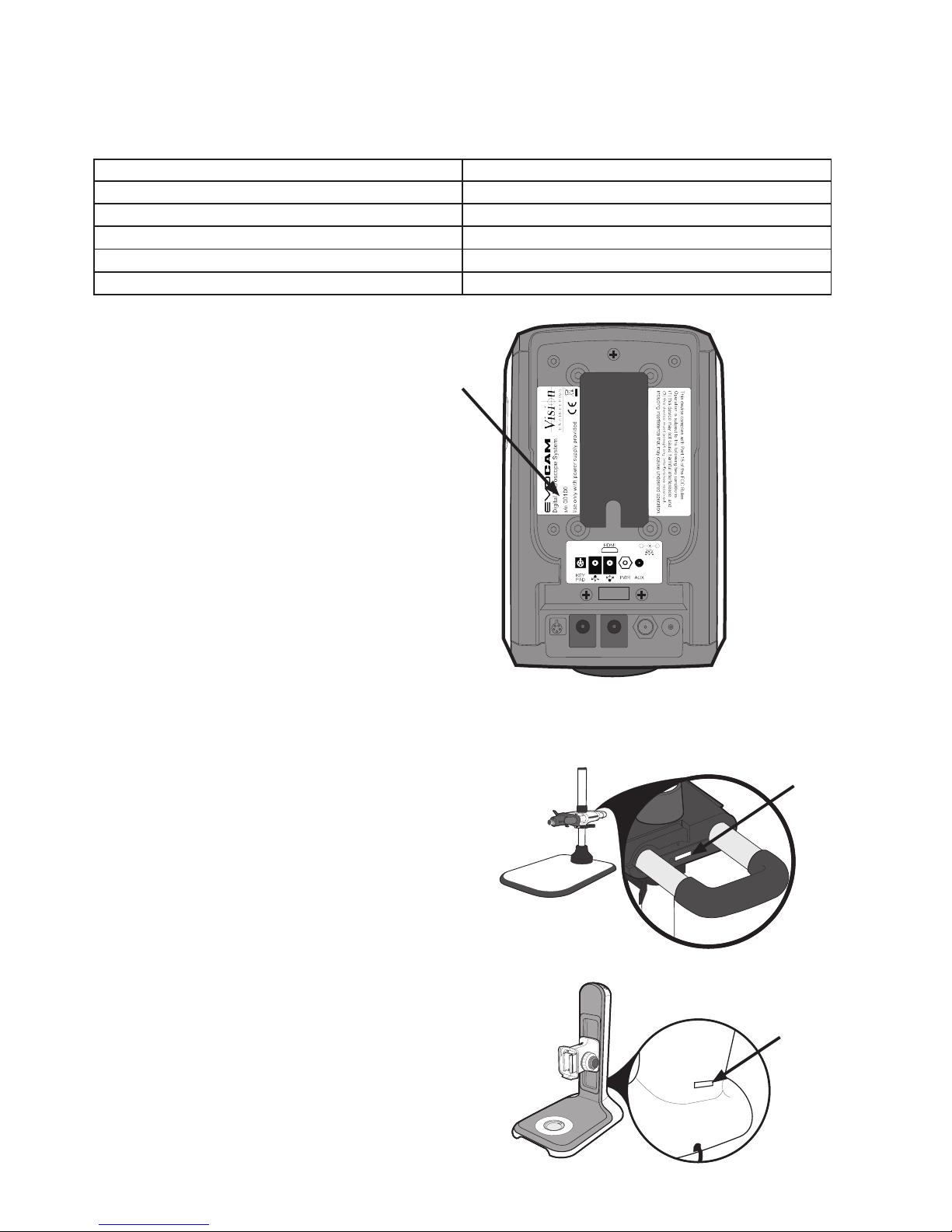
System serial numbers
Unit type Serial number
EVO Cam
Multi-axis stand
Ergo stand
Focus assembly
Transmitted substage illumination module (option)
EVO Cam
On the rear of the unit.
Multi-axis stand
On the rear of the stand mechanism.
Ergo stand
At the base of the column at the back.
S/N
S/N
S/N
Page 3
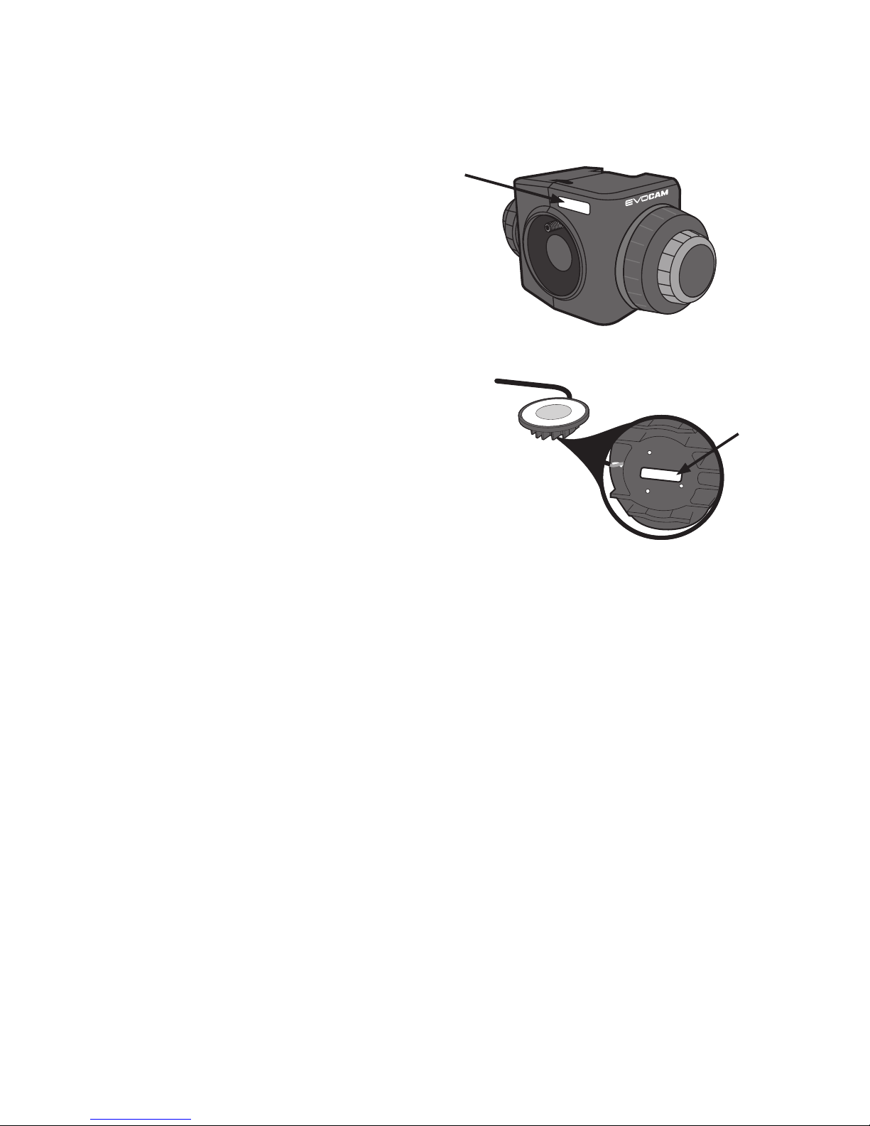
Focus assembly
On the rear of the unit.
Transmitted substage illumination module (option)
On the underside of the module.
.
S/N
S/N
Page 4

Copyright
Copyright © 2015 Vision Engineering Ltd., Send Road,
Send, Woking, Surrey GU23 7ER, UK All Rights Reserved.
Mantis® (1532468), Lynx® (3672061) and Dynascope®
(915579) are registered trademarks of Vision Engineering
Ltd. The use of our trademarks is strictly controlled and
monitored and any unauthorised use is forbidden.
Copyright in this document is owned by Vision
Engineering Ltd. Any person is hereby authorised to
view, copy, print and distribute this document subject to
the following conditions:
§ The document may be used for informational purposes
only
§ The document may be used for non-commercial
purposes only
§ Any copy of this document or portion thereof must
include this copyright notice
Revision 1.0, published July 2015 by:
Vision Engineering Ltd.
Send Road, Send
Woking, Surrey, GU23 7ER, UK
www.visioneng.com
Disclaimer
This document is provided “as is” without any warranty
of any kind, either express or implied, statutory or
otherwise; without limiting the foregoing, the warranties
of satisfactory quality, tness for a particular purpose or
non-infringement are expressly excluded and under no
circumstances will Vision Engineering Ltd. be liable for
direct or indirect loss or damage of any kind, including
loss of prot, revenue, goodwill or anticipated savings.
All such warranties are hereby excluded to the fullest
extent permitted by law.
We have compiled the texts and illustrations as accurately
as possible. However, Vision Engineering Ltd. will not be
responsible for the accuracy of the information contained
in this document, which is used at your own risk and
should not be relied upon. The information included in
this manual may be changed without prior notice.
Page 5
OPERATION
Quick start 6
Control functions 7
Illumination control 7
Image capture 7
Magnication 8
Magnication level OSD (On Screen Display) 8
Overview 8
Brightness 8
Factory defaults 9
Auto-white balance 9
Main menu options 9
Using the control console (optional) 11
Changing the camera objective lens 11
MAINTENANCE
Troubleshooting 12
Changing the output frame rate 12
Taking care of your evo cam 12
FIRMWARE UPGRADE
Firmware upgrade 13
Lighting controller rmware update 13
SPECIFICATION
SERVICING
Service record 15
WARRANTY
PREFACE
System serial numbers ii
EVO Cam ii
Multi-axis stand ii
Ergo stand ii
Focus assembly iii
Transmitted substage illumination module (option)
iii
Copyright iv
Disclaimer iv
General vi
Safety vi
Cleaning vi
Servicing vi
Symbols used vi
Warning! vi
Warning of electrical shock hazard vi
Important information vi
Health & safety vi
Electrical safety vi
Illumination safety vi
Environmental considerations vi
Operator wellbeing vi
Compliance statements vi
SYSTEM DIAGRAM
Sub-assemblies 1
Optical data 1
Stand options 2
Transmitted substage illuminator (option) 3
Stand mounts 4
Ergo stand 4
Multi-axis stand 4
Objective lens 5
Cabling 5
Page 6

Illumination safety
§ Do not look directly at the illuminated LED’s. This may
cause damage to the eyesight.
Environmental considerations
§ Avoid large temperature uctuations, direct sunlight
and vibrations.
§ Ensure electrical components are at least 10cm from
walls and combustible materials.
§ Position the system on a rm, rigid and level table.
§ The equipment should be positioned so that access to
the electrical input connector is always available.
§ Avoid positioning your system where bright reections
may affect the image.
Operator wellbeing
§ The advanced ergonomic design and construction
of Vision Engineering products are intended to
deliver superior ergonomic performance, reducing
the exertion of the user to a minimum. Depending
on the duration of uninterrupted work, appropriate
measures should be taken to sustain optimal operator
performance. This could include: Optimal arrangement
of workplace; Variation in task activity; Training of
personnel on workplace ergonomics and general
health and safety principles.
§ It is important to set-up and optimise your working
environment correctly in order to obtain maximum benet
from the advanced ergonomic design of your system. For
more information visit: www.visioneng.com/ergonomics
Compliance statements
Vision Engineering and its products conforms to the
requirements of the EC Directives on Waste Electrical and
Electronic Equipment (WEEE) and Restriction of Hazardous
Substances (RoHS).
All Vision Engineering products conform to the CE mark,
demonstrating that each product meets the requirements
of the applicable EC directives. Where applicable, other
characteristics of the CE directive are implied such as
essential health and safety requirements from all the
directives that applies to its product, including low
voltage directive and the EMC directive.
General
Safety
Before using your system for the rst time, please read
the Health & safety section of the user guide.
Ensure that:
§ Your system and accessories are operated, maintained
and repaired by authorised and trained personnel only.
§ All operators have read, understood and observe the
user manual, in particular the safety regulations.
Cleaning
§ Disconnect your system from the electrical source
before cleaning.
§ Do not use any unsuitable cleaning agents, chemicals
or techniques for cleaning.
§ Never use chemicals to clean coloured surfaces or
accessories with rubberised parts.
§ Use a specialist lens cloth to clean optical surfaces.
Servicing
Repairs may only be carried out by Vision Engineeringtrained service personnel. Only original Vision
Engineering spare parts may be used.
Symbols used
Warning!
A potential risk of danger exists. Failure to comply can
cause i) a hazard to personnel; ii) instrument malfunction
and damage. Please consult the operating instructions
provided with the product.
Warning of electrical shock hazard
This symbol indicates the presence of electric shock
hazards. Please consult the operating instructions
provided with the product.
Important information
This symbol indicates important information. Please
carefully follow the instructions or guidelines.
Health & safety
Unauthorised alterations to the instrument or
non-compliant use shall invalidate all rights to
any warranty claims.
Electrical safety
§ Disconnect your system from the electrical source
before undertaking any maintenance.
§ Avoid using any form of liquid near the system.
§ Do not operate your system with wet hands.
Page 7
SYSTEM DIAGRAM
www.visioneng.com/support
1
SYSTEM DIAGRAM
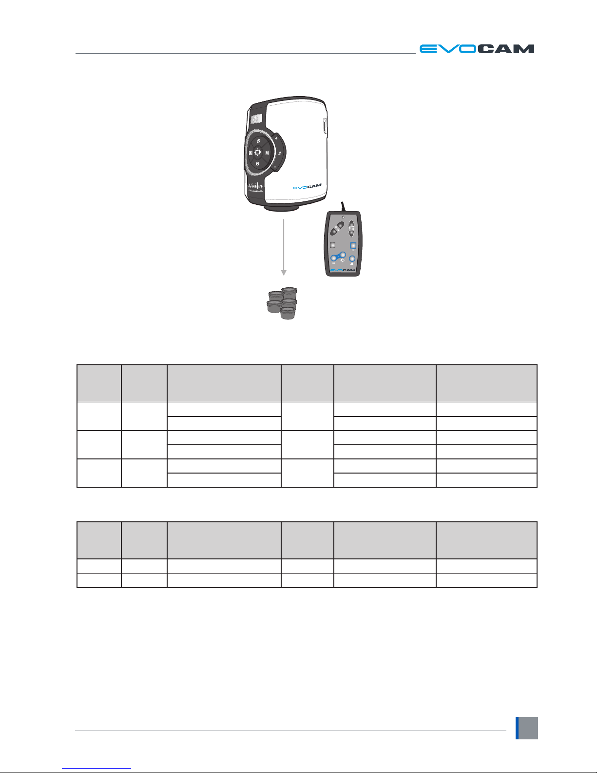
Sub-assemblies
Optical data
Objective
lens
Part
number
Magnication
zoom range*
Working
distance
Field of view
at min. zoom
(width / height)
Field of view
at max. zoom
(width / height)
0.45x ECL045
Full eld: 4.0x – 67x
176mm
134mm / 75mm 8.0mm / 4.5mm
Optimal: 6.7x – 67x 80mm / 45mm 8.0mm / 4.5mm
0.62x ECL062
Full eld: 5.5x – 92x
128mm
95mm / 53mm 5.7mm / 3.2mm
Optimal: 9.2x – 92x 57mm / 32mm 5.7mm / 3.2mm
1.0x ECL100
Full eld: 8.9x – 148x
75mm
55mm / 31mm 3.3mm / 1.9mm
Optimal: 14.8x – 148x 33mm / 19mm 3.3mm / 1.9mm
* with 25” monitor
Objective
lens
Part
number
Magnication
zoom range*
Working
distance
Field of view
at min. zoom
(width / height)
Field of view
at max. zoom
(width / height)
4 dioptre ECL040 1.8x – 52x 250mm 295mm / 172mm 10.3mm / 5.8mm
5 dioptre ECL050 2.3x – 65x 200mm 234mm / 137mm 8.2mm / 4.6mm
* with 25” monitor
Objective lenses
Control Console
EVO Cam
(see Optical data tables)
MEM
M3
AF/MF
M2
M1
AE/ME
ECH 002
ECX150
Page 8

SYSTEM DIAGRAM
www.visioneng.com/support
2
Stand options
Multi-axis stand
Focus assembly
Ergo stand
with focus
Transmitted substage illumination
EVS011
EVB020
EVF111
Multi-directional
floating stage
EVS120
EVB010
Page 9
ASSEMBLY
www.visioneng.com/support
3
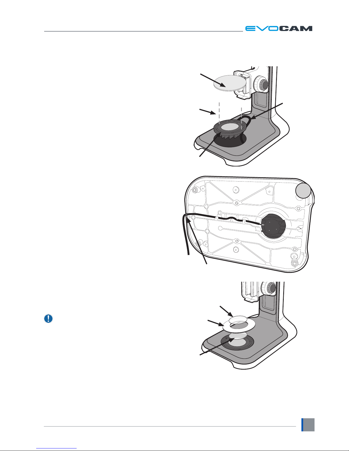
Transmitted substage illuminator
(option)
` Remove the stage cover plate u and thread the
lead v through the stand base.
` Locate the illuminator w into the stage base and
secure it with the 2 screws x.
` Carefully lay the Ergo stand on to its side and thread
the lead through the base as shown.
` Push the cable grommet y into the stand.
` Turn the Ergo stand upright and replace the illuminator
diffuser z shiny side up, surround { and glass |.
` Once EVO Cam is installed on the stand (see page 4)
connect the sub-stage power cable to the EVO Cam.
If assembling the optional glare reducing lter,
this needs to be placed between the diffuser and
the surround.
u
x
v
w
|
{
z
y
Page 10
ASSEMBLY
www.visioneng.com/support
4
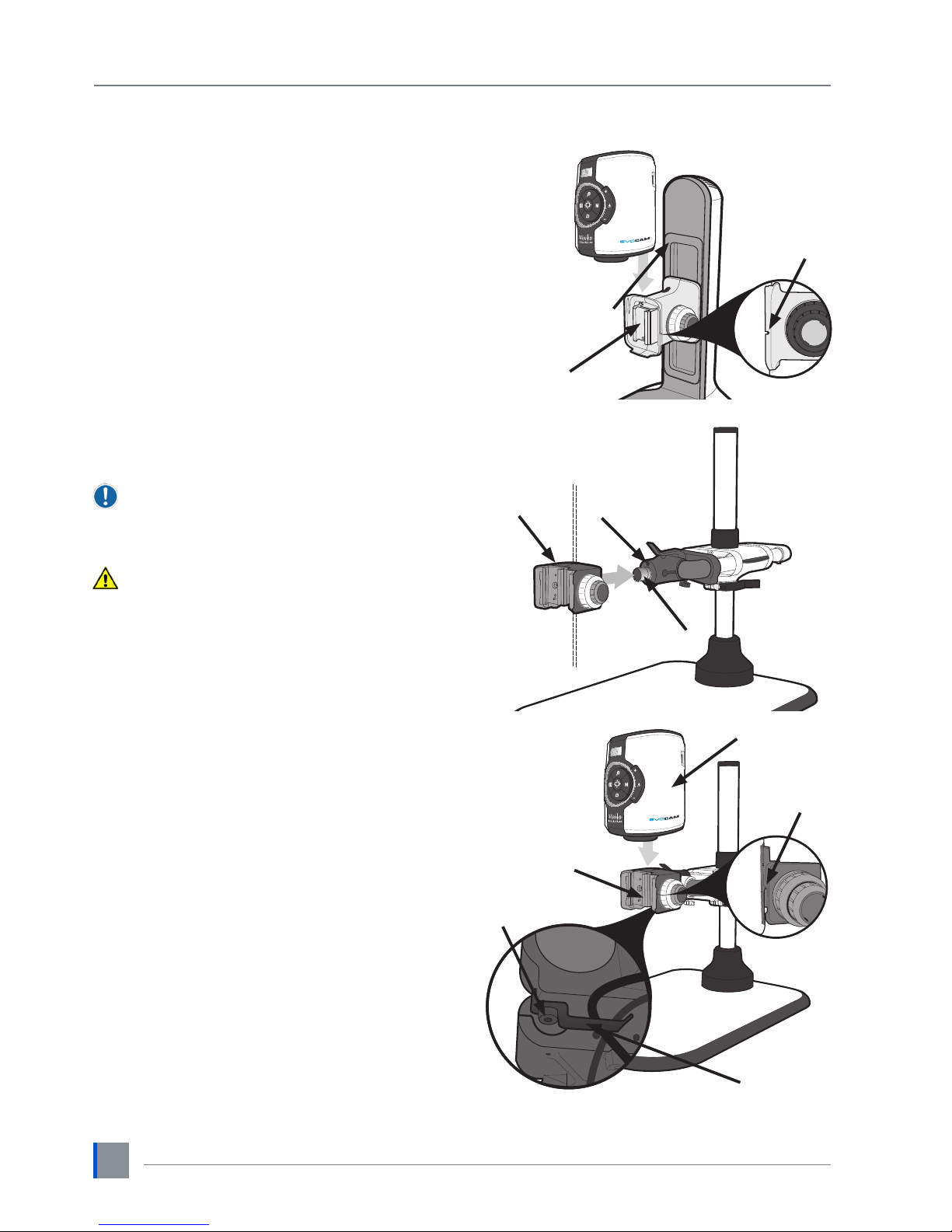
Stand mounts
Ergo stand
` Locate EVO Cam u on to the stand’s dovetail
interface v.
` Tighten securing grub screw w with Allen key
provided
Multi-axis stand
` Place focus assembly u on the mounting post v
so that the locator pin is located in the locator pin
recess w.
To change the camera rotation, remove the
locator pin from the focus assembly before
attaching it to the mounting post and attach the
focus assembly in the desired orientation.
Take care when mounting EVO Cam.
` Ensure the mounting plate is perpendicular to the
base or work bench.
` Tighten the 2x grub screws x at the top of the focus
assembly and the 2x grub screws y at the bottom of
the focus assembly.
` Locate EVO Cam u on to the stand’s dovetail
interface v.
` Tighten securing grub screw w with Allen key
provided
` Secure the cable retaining clip x under the knuckle
of the multi-axis stand using the screw y provided.
The clip can be secured to the left or right side.
v
w
u
v
w
u
y
x
w
u
v
y
x
Page 11
ASSEMBLY
www.visioneng.com/support
5
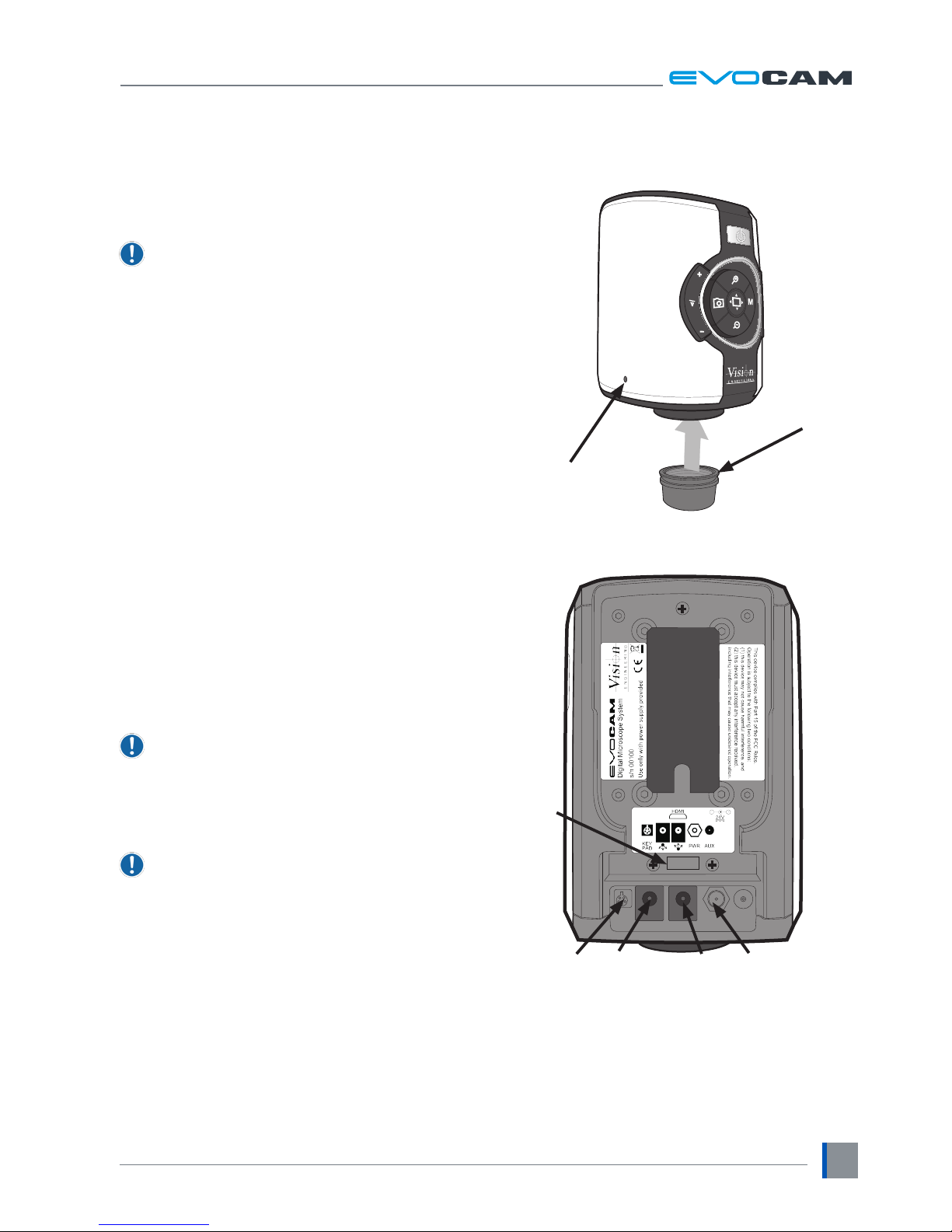
Objective lens
` While holding the objective lens u in position, use the
Allen key supplied to secure the lens by tightening
the grub screw v nger tight.
Do not over tighten the grub screw holding the
lens in place.
Cabling
` Plug the HDMI cable into the EVO Cam connector u
and the other end into your HDMI-compatible monitor
or TV.
` Plug the external Control Console (optional) into the
4-pin socket v at rear of EVO Cam.
` Plug the transmitted substage illuminator cable into
the connector w on the rear panel of EVO Cam.
The transmitted substage illuminator is an option
for use with the Ergo stand.
` If required, an external ringlight (option) can be used
with EVO Cam. Plug the external ringlight into the rear
panel connector x of EVO Cam.
Only use a Vision Engineering-authorised
external ringlight with EVO Cam.
` Plug the power supply into a mains socket. Plug the
power lead from the power supply into the EVO Cam
power connector y on the back of the unit.
u
v
yv wx
u
Page 12
OPERATION
www.visioneng.com/support
6
OPERATION
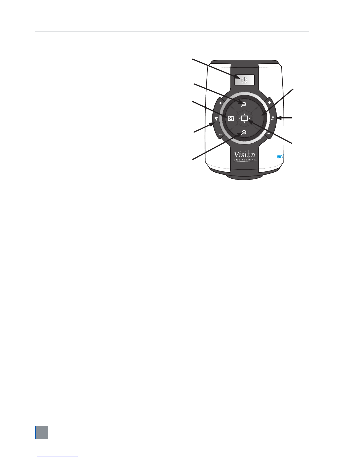
Quick start
u
Power on/off
v
Zoom in
w
Zoom out
x
Image capture
y
Transmitted substage illuminator (option)
z
Overview mode
{
Ringlight illumination control
|
Menu
Power on/off
u
- Short press = Power on
- Long press = Power off
Zoom control
v
- Zoom in
w
- Zoom out
Image capture
x
- Capture image
Transmitted substage illuminator (option)
y
- Press ‘+’ to increase brightness
- Press ‘–’ to decrease brightness
Overview mode
z
- Short press = Activate overview mode
(Press any button to exit overview mode)
Ring-light illumination control
{
- Press ‘+’ to increase brightness
- Press ‘–’ to decrease brightness
Menu
|
- Short press = Access camera menu
(Press | to exit menu)
M
u
v
w
x
y
z
{
|
Image brightness mode
|
- Long press to activate image brightness mode
v
- Press to increase image brightness
w
- Press to decrease image brightness
Activate auto white balance
z
+ | - Short press together
Toggle frame rate (50fps/60fps)
From off, press and hold u + z until 4 quick beeps are
heard.
Reset factory defaults
From off, press and hold u + | until 4 quick beeps are
heard.
Page 13
OPERATION
www.visioneng.com/support
7
Control functions
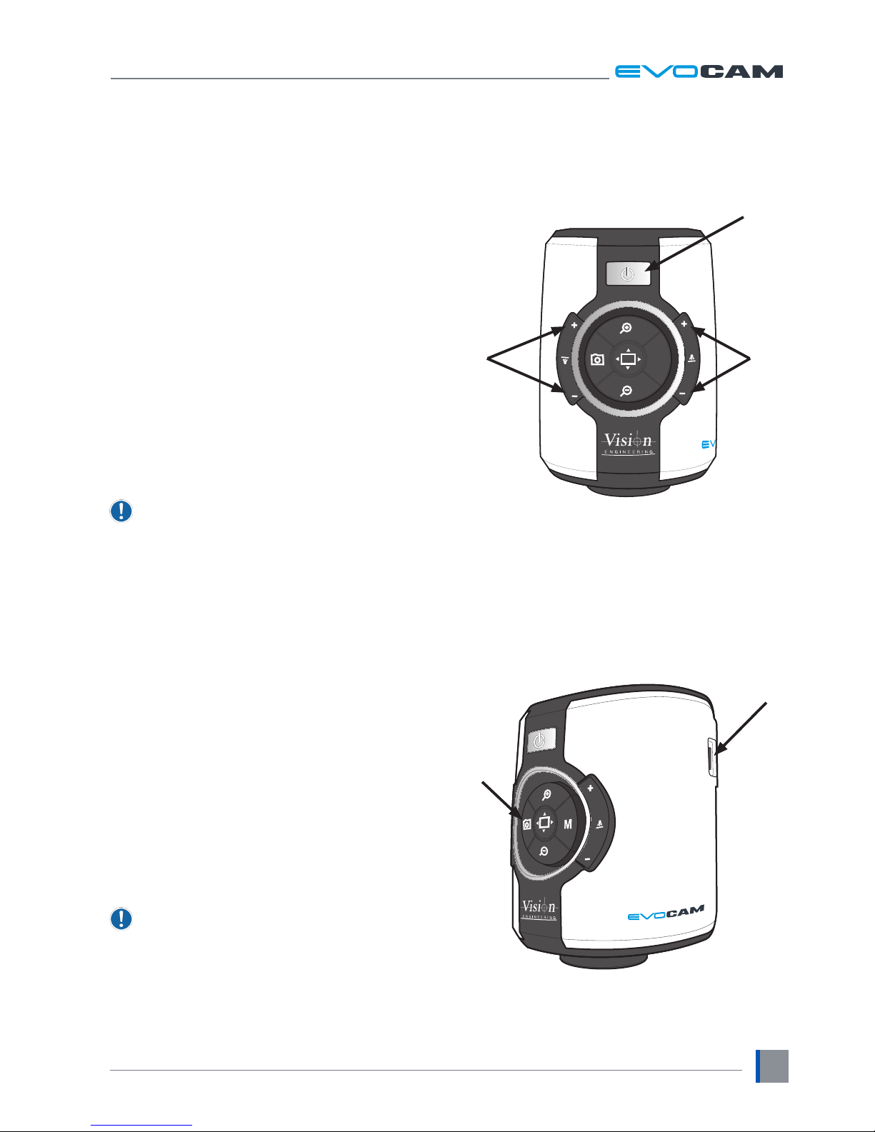
` Push the power button u to turn the unit on. A blue
image will appear on your screen and after a few
seconds the picture from the camera will appear. If
not, switch your monitor to the input used for EVO
Cam.
` Hold the Power button in for ~3 seconds to power
off EVO Cam.
Illumination control
` The integrated ringlight illumination level can be
adjusted by the right hand side buttons v.
` The optional sub-stage illuminator intensity can be
adjusted using the left hand side buttons w.
` When connected, the external rightlight illumination
level can be adjusted using the right hand side
buttons v.
The internal ringlight is disabled when the
external ringlight is connected.
Image capture
` To use this feature, insert a USB memory stick into
the USB port u.
` When the system has detected the USB memory stick
it will report “USB Key Ready”
` When you have an image you want to capture, simply
press the capture button v.
` The system will indicate the image is being saved
to the drive and indicate when the image has been
saved. The image is saved as a 1920 x 1080 bitmap
(.bmp) format.
` The image name is Date and Time stamped and saved
in the format: “IMG-DateTime.bmp”.
The USB memory stick must be in FAT File System
Format. It will not work with any other format.
M
v
u
w
u
v
Page 14
OPERATION
www.visioneng.com/support
8
Magnication
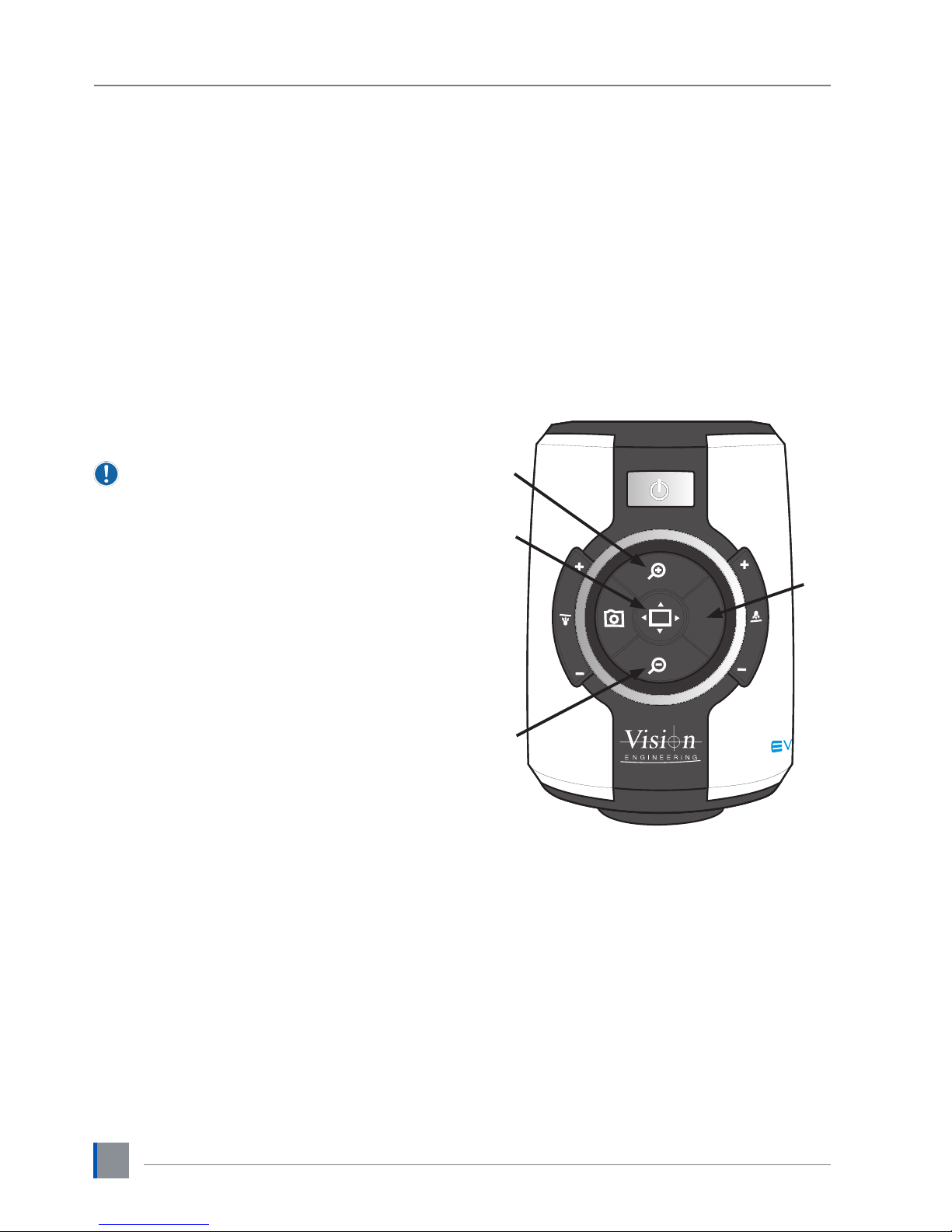
` Press the Zoom-In button u to enlarge the subject
within the image and Zoom-Out button v to reduce
the subject size within the image. The unit will make
a sound to indicate when it has reached maximum or
minimum zoom limits.
Magnication level OSD (On Screen
Display)
The current magnication level is displayed for example
“x30“to show a magnication level of 30. When
the magnication changes from optical to digital
zoom a‘ d’ is also displayed, e.g. “x60d” to indicate a
magnication level of 60 including digital zoom.
When changing lenses or monitor, the Lens Power
and Screen Size settings need to be changed
using the menu options (see page 9) to ensure
the correct magnication is displayed.
Overview
Overview allows you to easily locate a point of interest
on the object you are viewing.
` Press and release the Overview button w to make
the camera zoom out fully. A cross is displayed in the
centre of the screen as an aid to location.
` Place the point of interest under the cross and press
any key to restore the magnication to the previous
level.
Brightness
The image brightness can be adjusted to suit your
preference.
` Brightness adjustment is available by pressing and
holding the Menu button x until you should hear
a beep.
` Next use the Zoom In and Zoom Out buttons (u and
v
) to adjust the image brightness as desired.
` Press the Menu button again to save the setting and
exit Brightness mode. The setting you choose will
be saved and used subsequently for that mode of
operation.
M
u
v
w
x
Page 15
OPERATION
www.visioneng.com/support
9
Factory defaults
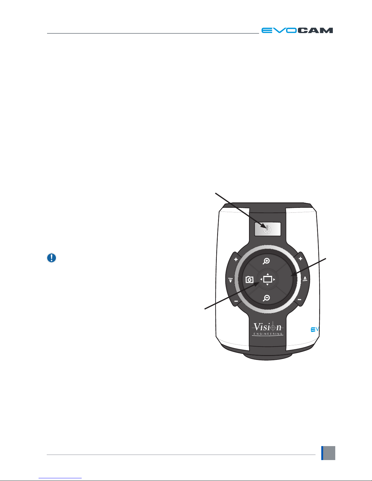
To restore EVO Cam to it’s factory settings follow the
procedure below:
` Ensure EVO Cam is turned off.
` Press and hold the power u and Menu v buttons
until 4 beeps are heard.
` EVO Cam will then turn on and display default
information.
` Press any button to exit the display and resume
operation.
Auto-white balance
White balance is the process of removing unrealistic
colour casts, so that objects which appear white are
rendered white on the display.
` Place a white sheet under the camera and ensure
that it covers more than half the image.
` Press the Menu v and Overview w buttons together
and the EVO Cam will automatically perform a White
Balance operation.
White Balance data is lost when the power is
turned off. If the power is turned off, set the
White Balance again using this method.
Main menu options
` To access the Main Menu press the Menu button v.
` The Menu will appear on the top of the screen
including the menu navigational controls.
` To Exit the menu at any time simply press the
overview button w.
The following menu options are available.
Sound: On / Off
Enable or disable the system sound.
Crosshair: On / Off
Enable or Disable the two articially generated lines
that appear on the screen in both the horizontal and
vertical directions which cross at the centre of the
image.
M
u
w
v
Page 16
OPERATION
www.visioneng.com/support
10
Crosshair: Long / Short
Select the Crosshair size – Short or Long.
Select the crosshair colour
Cross Col: White / Green / Blue / Red / Yellow / Purple
/ Cyan
Bright: Levels 1 – 15
The image brightness can be adjusted to suit your
preference.
White Balance: On / Off
Turns the auto white balance on / off.
Focus: Manual / Auto
Select between manual and auto focus modes. When
manual focus is selected EVO Cam’s internal focus is
xed - use focus control on the microscope stand to
adjust focus in this mode.
Infrared: On / Off
Normally the system lters out Infrared light.
Turning the Infrared On allows this spectrum of light to
pass through to the camera.
When the Infrared mode is turned on the image
becomes black and white.
Cam WDR: Off / WD / VE
The Wide Dynamic Range mode is a function for
dividing an image into several blocks and correcting
blocked-up shadows and blown-out highlights in
accordance with the intensity difference.
It enables you to view images with large intensity
differences.
WD – Images with Wide Dynamic Range are re-
produced by combining long exposure signals with
high-intensity signals obtained with short exposure.
VE – Using the Visibility Enhancer function will make
the darker part of a camera image brighter as well as
automatically correct brightness and contrast to show
parts clearly without overexposure.
Pick the option which shows the best results in your
application.
Noise R: -3 to 2
The Noise Reduction function removes noise to provide
clearer images.
Screen Size: 7 – 100
Enter the size of your display in inches (Measured
Diagonally) . This size is used to calculate the
magnication levels.
Lens Power: x0.45of, x0.62of, x1.0of, x0.45ff,
x0.62ff, x1.0ff, x1.0av, 4 dioptre, 5 dioptre
Enter the Lens power / dioptre number of the lens to be
used. This is used to calculate the magnication levels.
‘of’ is short for Optimal Field, ‘ff’ is short for Full
Field and ‘av’ is short for All-round View
Unit: Metric / Imperial
Select the units for cursor and grid measurements.
Show OSD: On / Off
Turning the On Screen Display (OSD) off removes all the
static messages from the screen. The menu will still be
displayed when the menu mode is entered.
Time: xx:xx
Enter the current time starting with minutes and then
hours.
Time and Date are only used to Date Stamp the
captured images.
Date: xx/xx/xxxx
Enter the current date starting with day, month and
then the year.
Time and Date are only used to Date Stamp the
captured images.
Rev: xxxxxxxxxx
Displays the rmware revision number of the system.
This may be required for support issues.
Page 17
OPERATION
www.visioneng.com/support
11
Using the control console (optional)
An optional control console can be used with EVO
Cam which allows many of EVO Cam’s controls to be
operated remotely.
The control console can also be used to navigate EVO
Cam’s menu and select items.
For full details of the control console, refer to the
accompanying user guide.
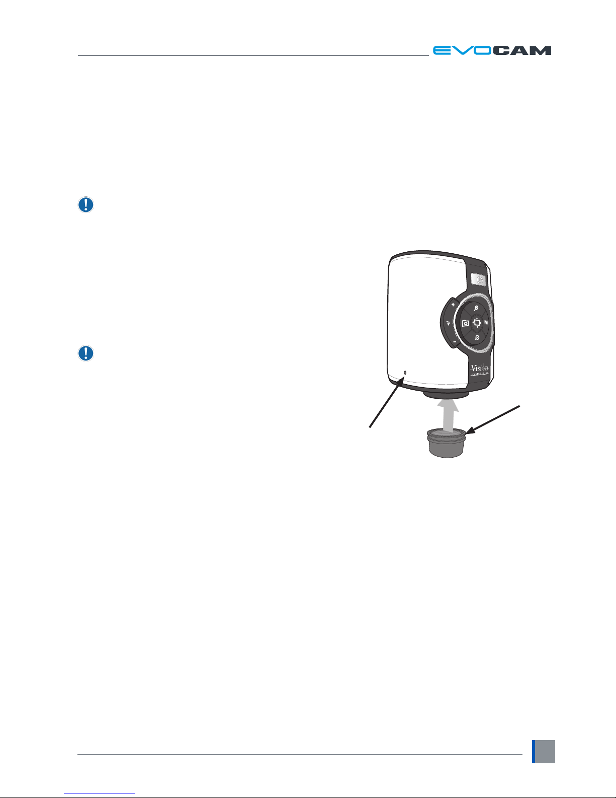
Changing the camera objective lens
` Holding the lens barrel u from the bottom, use
the Allen key supplied to partially unscrew the grub
screw v releasing the lens from its housing.
` While holding the objective lens u in position,
use the Allen key supplied to secure the lens by
tightening the grub screw v.
Do not over tighten the grub screw holding the
lens in place.
u
v
Page 18
MAINTENANCE
www.visioneng.com/support
12
MAINTENANCE
Troubleshooting
Changing the output frame rate
Most monitors and HD televisions can display all the many
different standards of HD signals, however some cannot.
If your monitor/TV does not display the image from the
EVO Cam you should try the following: ensure EVO Cam
is turned off. Press and hold the Overview and power
buttons until 4 quick beeps are heard. This will change
between 50Hz and 60Hz modes and display the selected
frequency. Press any key to continue using EVO Cam.
Taking care of your EVO cam
Do not touch the lens. Dirt on the lens will appear as a
blurred or dim image or as fuzzy spots on the screen. If you
believe the lens is dirty, it can be cleaned with a soft, dry
cloth applying minimal pressure. As the lens is polished and
coated, do not use a wet or coarse cloth, avoid detergents
and abrasive substances or solvents to clean it.
Never look directly at the LED light source for any
prolonged period of time.
Use only the supplied power supply and inspect the
cabling regularly for damage.
EVO Cam contains a small battery to enable
time and date settings to be retained while the
unit is powered off. Should the battery need
replacing please contact you Vision Engineering
representative who will be able to advise you.
Page 19
FIRMWARE UPGRADE
www.visioneng.com/support
13
FIRMWARE UPGRADE
Firmware upgrade
EVO Cam includes a Firmware Upgrade Function
allowing users to install new versions of the rmware.
` Make a directory called “Upgrade” in a USB memory
stick. If the directory already exists then delete all the
.bin les from that directory.
` Copy the two upgrade les to this “Upgrade” directory.
The les should be in the format “ARMxxxx.bin” and
“FPGAxxxx.bin”. The “xxxx” shows the version number.
` To enter the Firmware Upgrade Function, power up
the system with the front panel Zoom In and Zoom
Out buttons pressed.
` The system will make a sequence of 5 beeps upon
entry to the Firmware Upgrade Function.
` A beeping sound will be emitted until a USB Flash
Drive is detected. If no drive is detected the system
will timeout after approximately 20 seconds and turn
on normally.
` To exit the Firmware Upgrade function before the USB
drive is detected, simply power cycle the system by
pressing the Power Button.
` When the USB memory stick is detected, the Firmware
Upgrade Function searches the “Upgrade” directory
for the 1st le with the name format “ARMxxxx.bin”
and upgrades the ARM processor.
` The Firmware Upgrade Function then searches for
the 1st le with the name format “FPGAxxxx.bin”
and upgrades the FPGA Firmware.
` NB:- The Firmware Upgrade Function will use the 1st
le with the correct name format it nds. Therefore
it is recommended that you only have the rmware
version that you want to install in the “Upgrade”
directory and not multiple versions.
` During the upgrade process beeping sounds will be
emitted indicating progress.
` When the upgrade is complete the system will
automatically restart with the new version.
Lighting controller rmware update
In addition to the standard upgrade, the light control
can be upgraded with new rmware. To upgrade the
light control rmware:
Copy the EVOLxxx.bin into the Upgrade directory on a
USB drive.
Power off the system, then press and hold the Menu,
Zoom in and Power button until 4 quick beeps are heard.
The system will start normally until the USB ash drive is
detected; it will then enter the light control upgrade mode
and display “UPGRADE IN PROGRESS” and emit a number
of beeps whilst the upgrade is uploaded and applied.
When the upgrade is complete the unit will emit a longer
beep and briey display “UPGRADE FINISHED”.
Use the illumination controls to re-set the illumination
level after the upgrade.
Important
If the USB memory stick is removed during the upgrade
process or contains a corrupt le, the system will not
restart and the upgrade process will have to be repeated.
Page 20
SPECIFICATION
www.visioneng.com/support
14
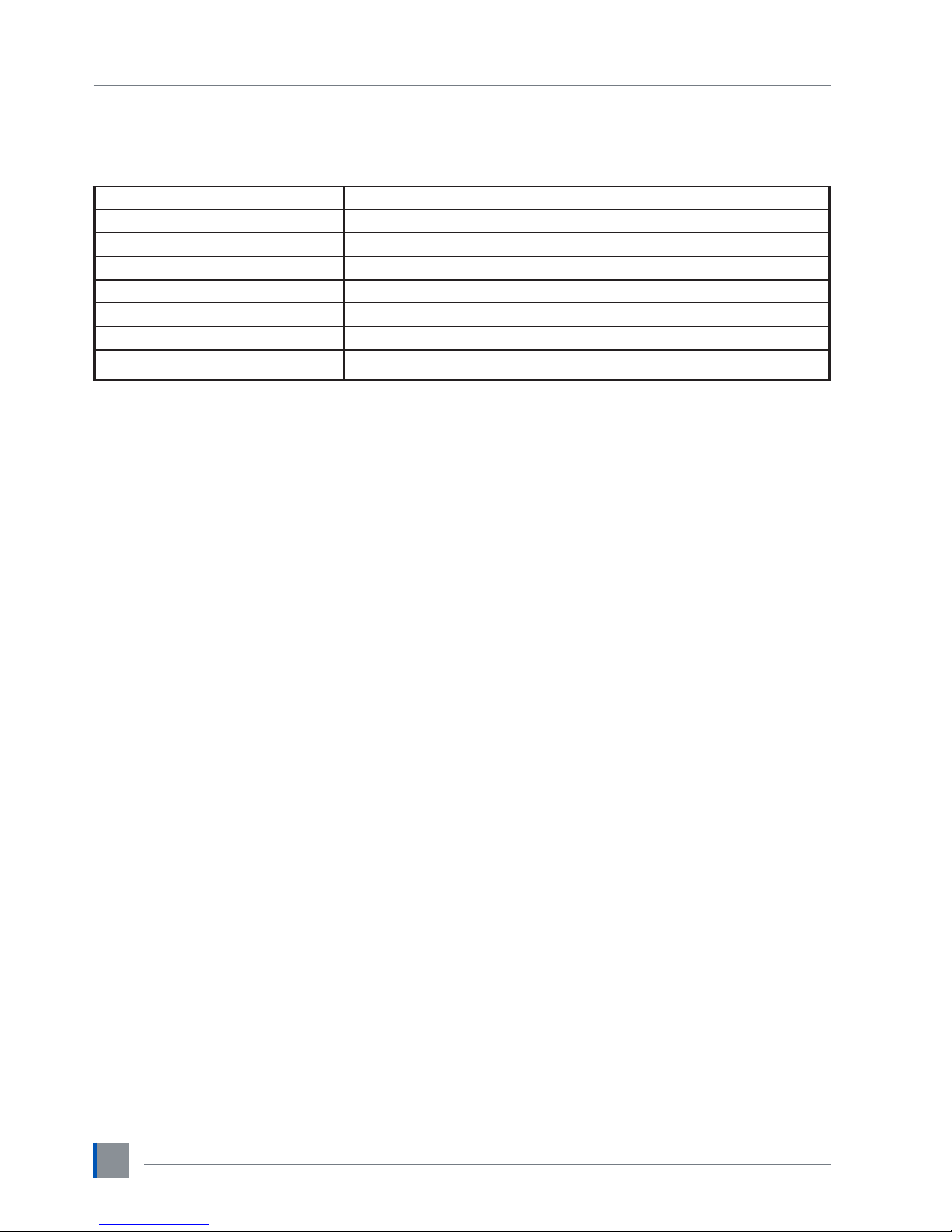
SPECIFICATION
Camera resolution: HD 1080p, 1920x1080 at 50/60 Hz
Monitor connections: HDMI
Monitor requirements: HD ready or full HD (recommended)
Outputs: HDMI
Image capture: USB 2.0 High-speed
Dimensions: 11 x 16.5 x 14 cm (w x h x d)
Power: Max. 72 Watts - depending on external attachments
Operating temperature: Storage: -10°C to +60°C. Operating: +5°C to +40°C
Page 21
SERVICING
SERVICING
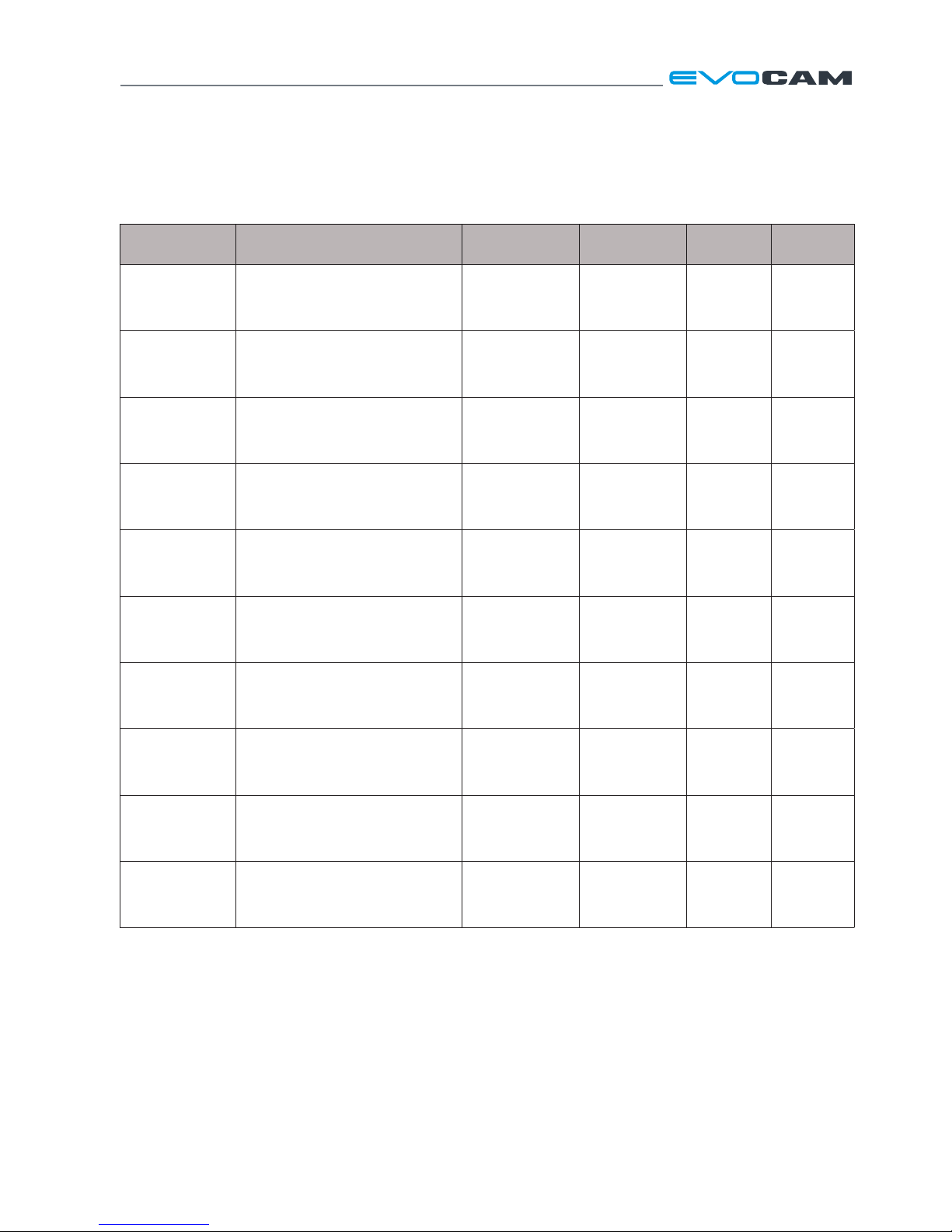
Service record
Service Comments Date of service
Date of next
service
Company Signature
Page 22

Page 23
WARRANTY
WARRANTY
This product is warranted to be free from defects in material and workmanship for a period of one year from the date
of invoice to the original purchaser.
If during the warranty period the product is found to be defective, it will be repaired or replaced at facilities of Vision
Engineering or elsewhere, all at the option of Vision Engineering. However, Vision Engineering reserves the right to
refund the purchase price if it is unable to provide replacement, and repair is not commercially practicable or cannot be
timely made. Parts not of Vision Engineering manufacture carry only the warranty of their manufacturer. Expendable
components such as fuses carry no warranty.
This warranty does not cover damage in transit, damage caused by misuse, neglect, or carelessness, or damage resulting
from either improper servicing or modication by other than Vision Engineering approved service personnel. Further,
this warranty does not cover any routine maintenance work on the product described in the user guide or any minor
maintenance work which is reasonably expected to be performed by the purchaser.
No responsibility is assumed for unsatisfactory operating performance due to environmental conditions such as humidity,
dust, corrosive chemicals, deposition of oil or other foreign matter, spillage, or other conditions beyond the control of
Vision Engineering.
Except as stated herein, Vision Engineering makes no other warranties, express or implied by law, whether for resale,
tness for a particular purpose or otherwise. Further, Vision Engineering shall not under any circumstances be liable for
incidental, consequential or other damages.
Page 24
Distributor
For more information...
Vision Engineering has a network of offices and technical
distributors around the world. For more information, please contact your
Vision Engineering branch, local authorised distributor, or visit our website.
Disclaimer – Vision Engineering Ltd. has a policy of continuous development and reserves the right to change or
update, without notice, the design, materials or specification of any products, the information contained within this
brochure/datasheet and to discontinue production or distribution of any of the products described.
LIT5209-ISS-01 Copyright © 2015 Vision Engineering Ltd. All rights reserved.
Visit our multi-lingual website:
www.visioneng.com
Vision Engineering Ltd.
(Central Europe)
Anton-Pendele-Str. 3,
82275 Emmering, Deutschland
Tel: +49 (0) 8141 40167-0
Email: [email protected]
Vision Engineering Ltd.
(France)
ZAC de la Tremblaie, Av. de la Tremblaie
91220 Le Plessis Paté, France
Tel: +33 (0) 160 76 60 00
Email: [email protected]
Vision Engineering Ltd.
(Italia)
Via Cesare Cantù, 9
20092 Cinisello Balsamo MI, Italia
Tel: +39 02 6129 3518
Email: [email protected]
Nippon Vision Engineering
(Japan)
272-2 Saedo-cho, Tsuduki-ku,
Yokohama-shi, 224-0054, Japan
Tel: +81 (0) 45 935 1117
Email: [email protected]
Vision Engineering
(China)
11J, International Ocean Building,
720 Pudong Avenue, Shanghai,
200120, P.R. China
Tel: +86 (0) 21 5036 7556
Email: [email protected]
Vision Engineering
(South East Asia)
P-03A-20, Impian Meridian,
Jalan Subang 1,
USJ 1, 47600 Subang Jaya,
Selangor Darul Ehsan,
Malaysia
Tel: +604-619 2622
Email: [email protected]
Vision Engineering
(India)
Email: [email protected]
Vision Engineering Ltd.
(
Manufacturing)
Send Road, Send,
Woking, Surrey, GU23 7ER, England
Tel:
+44 (0) 1483 248300
Email:
Vision Engineering Ltd.
(
Commercial)
Monument House, Monument Way West,
Woking, Surrey, GU21 5EN, England
Tel:
+44 (0) 1483 248300
Email:
Vision Engineering Inc.
(
Manufacturing & Commercial)
570 Danbury Road,
New Milford, CT 06776 USA
Tel:
+1 (860) 355 3776
Email:
Vision Engineering
(
Brasil)
Email: [email protected]
 Loading...