

Page 1
0
User Guide
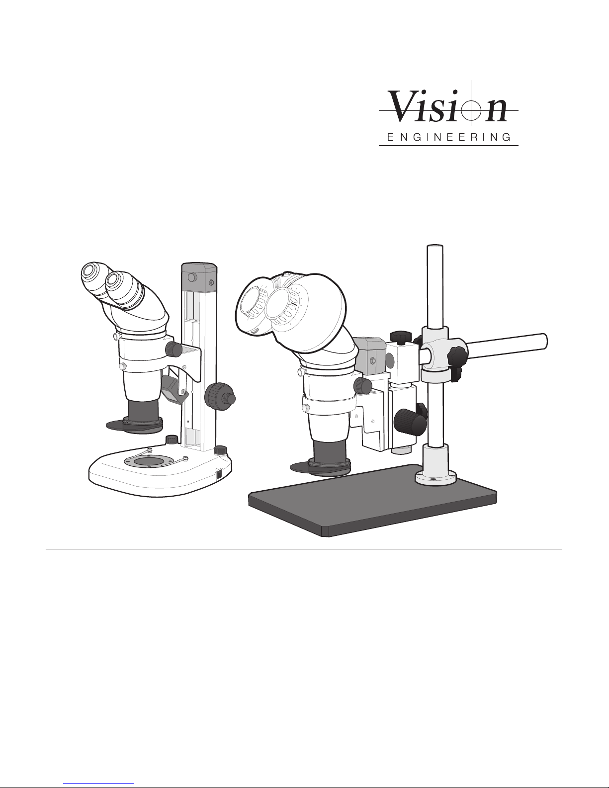
Ergo 80 stereo microscope
Page 2

Page 3

INTRODUCTION
Stereo microscope
Vision Engineering manufacture a wide range of patented optical systems, offering fatigue-free viewing with superb
hand-eye co-ordination, for improved quality and productivity.
To achieve the most from this precision instrument, please read the enclosed assembly instructions, usage and
maintenance guidelines.
Health & Safety
Vision Engineering and its products conforms to the requirements of the EC Directives on Waste Electrical and
Electronic Equipment (WEEE) and Restriction of Hazardous Substances (RoHS).
EN61326-1:2006
FCC Part 15
IEC 61010-1:2001
WARNING: ALL EQUIPMENT PLUGGED INTO THIS UNIT MUST BE APPROVED TO EN60950-1:2001 AND
CHECK CURRENT RATING OF OUTPUT SOCKET IF USED.
The equipment is connected to protective earth via the mains cable provided.
If the equipment is used in a manner not specied by Vision Engineering Ltd in this user guide, the protection
provided by the equipment may be impaired.
Warning symbols
This symbol, when used alone or in conjunction with the following symbol, indicates the need
to consult the operating instructions provided with the product.
WARNING: A potential risk of danger exists if the operating instructions are not followed.
This symbol indicates the presence of electric shock hazards. Consult the operating instructions
provided with the product wherever this symbol is found.
Page 4

UNPACKING
System by box content
Box 1 Stand (Boom or Bench as ordered)
Box 2 Zoom assembly
Box 3 Objective
Box 4 ISIS ergonomic eyepieces or standard eyepieces
Box 5 Dovetail adapter, power supply, control box, screws, cable clips and user guide
Box 6 Boom stand adapter and screws (if Boom stand ordered)
Box 7 Accessories
Page 5

CONTENTS
SYSTEM EQUIPMENT
Head 1
Stand 1
Illuminator 1
Optional equipment 2
Stage 2
Ergowedge 2
25° wedge 2
Unicam digital camera 2
Iris control 2
ASSEMBLY
Bench stand 3
Attaching the zoom assembly & objective 3
Attaching the head & control box 3
Boom stand 4
Attaching the boom stand interface bracket 4
Attaching the zoom assembly, objective, head & control box 4
Attaching the ringlight & antiglare screen 5
Attaching the head & optional iris control 5
Attaching the ergowedge 5
Attaching the 25° wedge 5
Attaching the unicam 6
Attaching the oating stage 6
Fitting the stage glass 6
Cabling 7
Isis adjustment 7
Using the iris control 7
Getting the most from your system 8
Routine maintenance 8
Tensioning 8
Environmental considerations 8
WARRANTY
Page
Page 6

Page 7

SYSTEM EQUIPMENT
www.visioneng.com/support Ergo 80 stereo microscope
1
SYSTEM EQUIPMENT
Head
ISIS ergonomic eyepieces
Standard eyepieces
Head adapter
Zoom assembly
Objective
Stand
Illuminator
Ringlight
Antiglare screen
Page 8

SYSTEM EQUIPMENT
Ergo 80 stereo microscope www.visioneng.com/support
2
Optional equipment
Stage
Floating stage
Stage adapter
Ergowedge
25° wedge
Unicam digital camera
Iris control
Page 9

ASSEMBLY
www.visioneng.com/support Ergo 80 stereo microscope
3
ASSEMBLY
Bench stand
Attaching the zoom assembly & objective
Ensuring all components are clean and dust-free, proceed as follows:
X Loosen the securing screw u.
X Lower the zoom assembly v into the stand’s head location ring w.
X Tighten the securing screw.
X Screw the objective lens x up into the zoom assembly.
Attaching the head & control box
X Place the adapter ring u on to the zoom assembly v
and using a 2mm Allen key, secure it with the securing
grub screw w.
X Place the head x on to the adapter ring and secure it by
tightening the securing screw y.
Note: The ISIS ergonomic eyepieces are illustrated
but the procedure for the Standard eyepieces
is the same.
X Remove the 2 securing screws z from the top cap {
and lift the cap off.
X Place the control box | on top of the stand, replace the
top cap and secure it in place with the replacement screws.
v
u
x
w
z
|
{
w
u
v
x
y
Page 10

ASSEMBLY
Ergo 80 stereo microscope www.visioneng.com/support
4
Boom stand
Attaching the boom stand interface bracket
X The boom stand interface bracket u is tted between the boom stand focus
assembly v and the head location ring w in a 2 stage process, using the
focus control x.
X Remove the head location ring.
X Turn the focus control clockwise until there is enough room
to secure the interface bracket via the top 2 location holes - see
inset A.
X Turn the focus control anticlockwise until there is enough
room to secure the interface bracket via the top 2
location holes - see inset B.
Attaching the zoom assembly, objective, head & control box
X Using the same procedures as detailed on page 3, attach
the zoom assembly u, objective v, head adapter
plate w and head x.
X Secure the control box y and its cap z to the
interface bracket { and secure it with the
screws provided |.
A
B
v
w
x
u
u
w
x
v
y
|
{
z
Page 11

ASSEMBLY
www.visioneng.com/support Ergo 80 stereo microscope
5
Attaching the ringlight & antiglare screen
X Raise the ringlight u into position over the objective v and secure
it by tightening the 3 grub screws w.
X Slide the antiglare screen x into the lower receptor groove
in the ringlight body.
Attaching the head & optional iris control
X Place the iris control u on to the zoom assembly v
and using the 2mm Allen key supplied, secure it with the securing
grub screw w.
X Place the adapter ring x on the iris control and secure it
with the securing grub screw y.
X Place the head z on to the iris control and secure it
by tightening the securing screw { using a 2mm
Allen key.
Note: The ISIS ergonomic eyepieces are illustrated
but the procedure for the Standard eyepieces
is the same.
Attaching the ergowedge
X Loosen the head adapter securing screw u and remove the head v.
X Place the ergowedge w on to the head adapter and retighten the
adapter securing screw.
X Place the head on to the ergowedge and tighten its securing screw x.
Note: The ergowedge provides the ability to tilt the head
-5 to -25 degrees
Note: The ISIS ergonomic eyepieces are illustrated
but the procedure for the Standard eyepieces
is the same.
Attaching the 25° wedge
X Loosen the head adapter securing screw u and remove the head v.
X Place the 25° wedge w on to the head adapter and retighten the
adapter securing screw.
X Place the head on to the 25° wedge and tighten its securing screw x.
Note: The ISIS ergonomic eyepieces are illustrated
but the procedure for the Standard eyepieces
is the same.
v
w
x
u
w
u
v
x
y
z
{
u
v
w
x
u
v
w
x
Page 12

ASSEMBLY
Ergo 80 stereo microscope www.visioneng.com/support
6
Attaching the unicam
X Loosen the head adapter securing screw u and remove the head v.
X Place the unicam w on to the head adapter and retighten the
adapter securing screw.
X Place the head on to the unicam and tighten its securing screw x.
Note: Refer to Unicam user guide for connection and operation.
Note: The ISIS ergonomic eyepieces are illustrated
but the procedure for the Standard eyepieces
is the same.
Attaching the oating stage
X Attach the stage adapter plate u to the stand v.
X Attach the stage w to the adapter plate.
Fitting the stage glass
X Position the stage glass u on to the stage v.
u
v
w
x
u
v
w
u
v
Page 13

OPERATION & SETUP
www.visioneng.com/support Ergo 80 stereo microscope
7
Cabling
X Connect the ringlight u to the left-hand connector on the control box v.
X Connect the Isis w to the right-hand connector on the control box.
X Connect power x to the rear of the control box.
Isis adjustment
Note: If you wear corrective eyeglasses, keep them on.
X Hold the body of the Isis and adjust the Isis eyepieces u until you have the
correct eyespacing. The view of the subject should now be comfortable.
Minor adjustments can be made using the Eyepiece Dioptre adjusters
v
for comfort (no more than 2 to 3 marks movement should be
necessary).
Using the iris control
X Move the control lever u to the left to reduce the Aperture,
and vice versa. Reducing the aperture has the effect of increasing
the visible depth of eld
v
u
w
x
v
u
u
Page 14

OPERATION & SETUP
Ergo 80 stereo microscope www.visioneng.com/support
8
Getting the most from your system
Routine maintenance
• The outside of the instrument should be wiped down with a damp cloth to remove dirt and dust.
• The instrument and accessories should be checked for loose or damaged components.
• When not in use, protect your system with the dust cover.
• Always disassemble the system prior to moving.
Tensioning
Note: The tensioning tool is available from Vision Branch Ofces.
Bench stand
X Attach special tensioning tool u to the inner collar of the left-hand
focus knob v and turn the tool clockwise.
Boom stand
X Turn the right-hand focus knob u clockwise whilst turning the
left-hand focus knob in the opposite direction.
Environmental considerations
This equipment is designed for indoor use in the following conditions:
• Up to 2000m altitude
• Between 5° and 40°C ambient temperature (10° to 35° recommended limits)
• Power supply; 100-120V/ 220-240V, 50/60Hz with voltage uctuations up to 10% of the nominal voltage
• Transient over voltages typically present on the Mains supply
• Maximum relative humidity of 80% for temperatures up to 31°C decreasing linearly to 50% relative humidity at 40°C.
This system is an accurate, industrial gauging instrument. To achieve the optimum accuracy and repeatability, the
following considerations should be taken into account:
• Position the system on a rm, rigid and level table.
• Avoid locating the instrument near to a source of vibration.
• Do not place the instrument close to a radiator or similar heat source.
• Do not place the instrument close to a cold temperature source such as an air conditioning unit.
• Do not position the instrument in direct sunlight, or where bright reections will affect the image.
• The equipment should be positioned so that access to the mains input connector is always available.
v
u
u
Page 15

SERVICE RECORD
www.visioneng.com/support Ergo 80 stereo microscope
9
System Serial Number
Service Type Comments Date of Service
Date of Next
Service
Company Signature
Page 16

Page 17

WARRANTY
WARRANTY
This product is warranted to be free from defects in material and workmanship for a period of one year from the date
of invoice to the original purchaser.
If during the warranty period the product is found to be defective, it will be repaired or replaced at facilities of Vision
Engineering or elsewhere, all at the option of Vision Engineering. However, Vision Engineering reserves the right
to refund the purchase price if it is unable to provide replacement, and repair is not commercially practicable or
cannot be timely made. Parts not of Vision Engineering manufacture carry only the warranty of their manufacturer.
Expendable components such as fuses carry no warranty.
This warranty does not cover damage in transit, damage caused by misuse, neglect, or carelessness, or damage
resulting from either improper servicing or modication by other than Vision Engineering approved service personnel.
Further, this warranty does not cover any routine maintenance work on the product described in the user guide or any
minor maintenance work which is reasonably expected to be performed by the purchaser.
No responsibility is assumed for unsatisfactory operating performance due to environmental conditions such as
humidity, dust, corrosive chemicals, deposition of oil or other foreign matter, spillage, or other conditions beyond the
control of Vision Engineering.
Except as stated herein, Vision Engineering makes no other warranties, express or implied by law, whether for resale,
tness for a particular purpose or otherwise. Further, Vision Engineering shall not under any circumstances be liable
for incidental, consequential or other damages.
Page 18

Vision Engineering Ltd.
(Central Europe)
Anton-Pendele-Str. 3,
82275 Emmering, Deutschland
Tel: +49 (0) 8141 40167-0
Email: [email protected]
Vision Engineering Ltd.
(France)
ZAC de la Tremblaie, Av. de la Tremblaie
91220 Le Plessis Paté, France
Tel: +33 (0) 160 76 60 00
Email: [email protected]
Vision Engineering Ltd.
(Italia)
Via Cesare Cantù, 9
20092 Cinisello Balsamo MI, Italia
Tel: +39 02 6129 3518
Email: [email protected]
Nippon Vision Engineering
(Japan)
272-2 Saedo-cho, Tsuduki-ku,
Yokohama-shi, 224-0054, Japan
Tel: +81 (0) 45 935 1117
Email: [email protected]
Vision Engineering
(China)
11J, International Ocean Building,
720 Pudong Avenue, Shanghai,
200120, P.R. China
Tel: +86 (0) 21 5036 7556
Email: [email protected]
Vision Engineering
(India)
Email: [email protected]
Distributor
Visit our website:
www.visioneng.com
For more information...
Vision Engineering has a network of offices and technical distributors around
the world. For more information, please contact your Vision Engineering
branch, local authorised distributor, or visit our website.
Disclaimer – Vision Engineering Ltd. has a policy of continuous development and reserves the right to change or
update, without notice, the design, materials or specification of any products, the information contained within
this brochure/datasheet and to discontinue production or distribution of any of the products described.
Vision Engineering Ltd.
(Manufacturing)
Send Road, Send,
Woking, Surrey, GU23 7ER, England
Tel: +44 (0) 1483 248300
Email: [email protected]
Vision Engineering Ltd.
(Commercial)
Monument House, Monument Way West,
Woking, Surrey, GU21 5EN, England
Tel: +44 (0) 1483 248300
Email: [email protected]
Vision Engineering Inc.
(Manufacturing & Commercial)
570 Danbury Road,
New Milford, CT 06776 USA
Tel: +1 (860) 355 3776
Email: [email protected]
Vision Engineering Inc.
(West Coast Commercial)
745 West Taft Avenue,
Orange, CA 92865 USA
Tel: +1 (714) 974 6966
Email: [email protected]
LIT4837 R1.0/09/12
 Loading...