

Page 1

Ver. VD3000E 1.0E
CAR BLACK BOX
TM
User Manual
Page 2
2
3
6
7
8
9
10
11
20
29
38
INDEX
Before Use
Caution
Product Structure
Part Names
Product Specication
Installation Precautions
Installation Sequence
Intallation Procedure
Product Use
Analysis Program Use
Warranty
Page 3

Before Use
Thank you for choosing this product.
The following contents describe the responsibility scope of the warranty service
covered by us and the product cautions.
Before you use, full knowledge of the product is recommended before using.
Warranty Service and Responsibility Scope
We shall not held responsible for the damages caused by errors or data loss of
this product, as well as any damages or losses derived from the condition.
VD-3000 is designed to record, store, play and analyze the videos incurred by
impacts and car accidents or recorded by user’s discretion. However, it is not
assured that the product will record all videos in every environment.
Furthermore, under circumstances where the impact is too weak, the vibration
sensor may not be able to detect the impact, which induces that the system
will be unable to automatically start recording the [Event] le. In such a
situation, the urgent save button (SHOT) on the Vision Drive should be pressed
to start recording a video to the [Event] folder.
The information on this manual can change without notice due to technological
upgrades. Check for updates periodically to ensure full knowledge of both the
warranty service and responsibility scope.
Page 4
Caution
The Vision Drive SD card is the only usable SD card for Vision Drive.
In case of a lost or stolen SD card, please contact your local retail shop to
purchase a replacement.
Do not disassemble or remodel this product. It can cause an electric shock.
Any malfunctioning after such action will be cased due to untting use of
the product and no warranty service shall be provided. Consult the retailer
for product maintenance and repairs if necessary.
Only use adaptors with the appropriate specication. Not doing so will result
in defecting the product or cause re.
Using enclosed cables for other uses than advised will result in defect or re.
All wiring should be carefully implemented so the cable may not be
damaged.
When installing the device to your vehicle, follow all the procedures and
make sure the hold is secure. Unclean surface will weaken the adhesive
strength and can damage the product if it drops due to weak adhesion.
This product is not waterproof. Make sure to avoid liquids and impurities
entering the product..
Under the circumstances where the product is wired to the power supply
of the vehicle directly or if the cigar jack is connected to the power supply
while the engine is o, make sure to disengage the device to prevent
battery outage for your vehicle.
If a damaged or a non Vision Drive SD card is used, the recorded data
maybe damaged or will not record and/or replay due to dierence in
quality.
Page 5
Caution
Do not use chemicals or detergents to clean the device. This can result in
product malfunctioning.
Excessive tinting on the window may distort or reduce clarity of recorded
data.
Note that due to the use of camera on the product, recording can be
distorted under the condition that brightness suddenly changes such as
passing through a tunnel, direct sunlight reection on day time or where no
light is available at night time.
If not enough light is available, using fog light may help record better data.
In case of an accelerated impact, the product may not be able to record
automatically. In such a case, please use the (SHOT) button to record
manually.
Operating the product while driving is risky and may cause an accident.
Any operation should be done o the road inside a stopped vehicle.
If you eject the SD card while the product is on, the recorded data may be
damaged. Make sure the main power is completely o before removing the
SD card from the product.
Cumulation of impurities on the camera lense or the window surface near
the camera may result in distortion and reduced clarity of recorded data.
These places should always be kept clean.
Page 6
Caution
Dropping or giving an impact on the product during operation can cause
defect or re.
Do not keep the product in an extreme temperature or in humid areas. Being
under extreme heat in summer days or freezing cold in winter days may
result in defection of the product. Also, do not expose the product to direct
re or water.
In case of disassembly of the product, turn o the power completely.
Disassembly without caution may result in product defect.
Keep the SD card in its case while carrying or placing o the product. Static
electricity or other environmental elements can damage the recorded data.
Copy and keep important data on other data storages such as hard disk, CD,
portable ash memory.
We, the company, are not responsible for loss or destruction of stored data.
If the SD card is ejected or the system is turned o while recording,
copying or deleting a data, stored data may be lost or damaged. In a
worst case scenario, the SD card may become defective.
SD card is an expendable supply. After normal period of usage, the partial
memory sector may be damaged which will disable any recording of data.
The system installed on the SD card provide an automated checking
function. If use of the function is not stabilizing the system installed on the
SD card, we recommend purchasing a new SD card for recording data.
Page 7
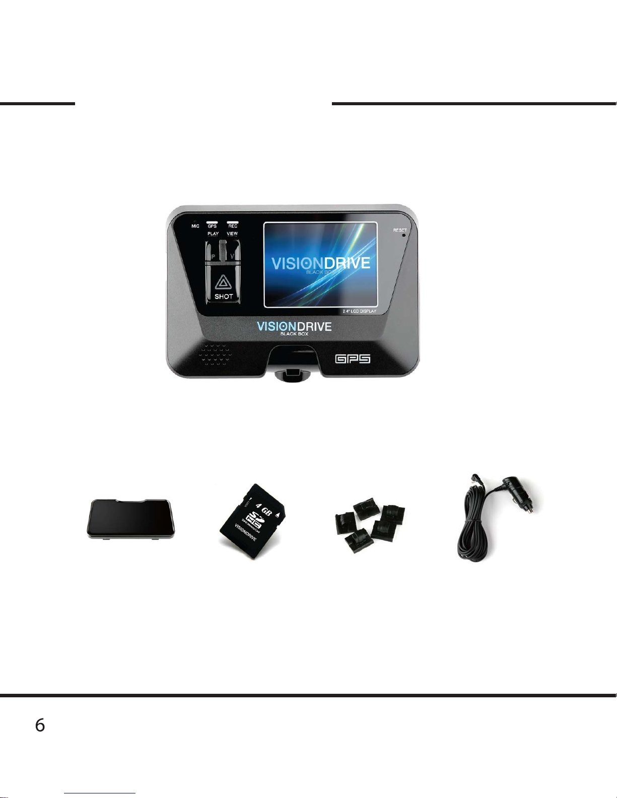
Product Structure
The manual and/or quick guide maybe provided on a digital le.
Product setting may change anytime without notice.
Attach Bracket Wire holders Cigar Jack Power AdaptorSD Card
(VD Analyzer Software
User Manual PDF)
Vision Drive Unit
Page 8

7
Part Names
For models with LCD screen
REC LED
GPS LED
MIKE
VIEW BUTTON
PLAY BUTTON
SHOT BUTTON
LCD SCREEN
GPS SENSOR
CAMERA
BRACKET ATTACHED TO THE UNIT’S BODY
POWER PORT
EXTERNAL GPS PORT
SD CARD SLOT
(FOR CONNECTING TO GPS SYSTEM
INSTALLED ON THE VEHICLE)
Page 9
8
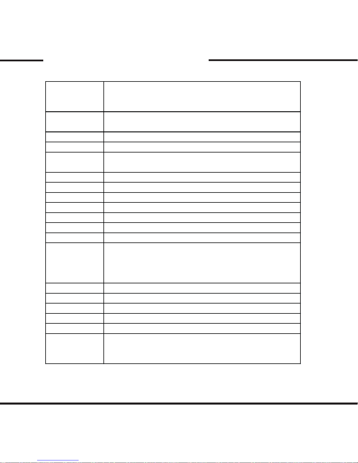
Product Specication
Camera
Resolution
LCD
GPS
Impact
Sensor
Memory
Sound Recording
Voice Notication
Power
Operatable Power
Operatable Temp
Consumption
Memory
Eciency
Buttons
Emergency Power
Minimum Light
Dimensions
Weight
PC Requirements
1 Camera (1.3 Mega Pixel CMOS digital camera)
2.4 inch Full color TFT LCD
Internal GPS Module
Event File : 10 seconds prior to impact,
15 to 60 seconds after the impact
(Multiple impact may lengthen the recorded time)
Normal File : 5 minutes per le
-20˚ to 65˚
2.4W
8V ~ 32V
12V ~ 24V (Cigar Jack)
Internal Speaker
CPU : Pentium4 or higher (CPU 2GHz and higher recommended)
Memory : 1G or higher RAM (RAM 2G and higher recommended)
OS system : Window XP/VISTA/WIindows 7
129g (excluding the bracket)
111mm x 75mm x 27mm (excluding the bracket)
1 Lux
EDLC
PLAY / VIEW / SHOT
Internal Mike
SD Memory Card (SDHC GBs : 4GB to 32GB)
1280x690 (HD) 15 frame/sec. Maxium
640x480 (VGA) 30 frame/sec. Maxium
Internal 3G Sensor
(x-y-z, Impact/Sudden Exceleration, Deceleration and Turn)
- Angles : 156˚ (Horizontal 120˚, Vertical 90˚)
- Rotation : Top to Bottom 60˚
Page 10
9
Installation Precautions
For safe installation and use, read all the information provided below.
This product only uses Vision Drive SD card.
(The program is installed in the SD card for the product to function properly.)
Intall the product after parking the vehicle in a bright and safe area.
Do not disassemble or make alteration to the product.
Disassemble only after the power is turned o completely.
Do not eject the SD card while the product is in operation.
Prior to the installation, clean the area of the installation where the
camera will be positioned.
Use the power cable provided in with the product for the cigar jack
connection for power range of DC12V to DC24V. If wiring is involved,
we recommend using a professional for the installation.
Intall after ignition is off, especially after the power source has been
turned off completely.
For the intial use, do not disconnect power supply till the system
boots completely.
Be aware of engine ignition for it momentaly disconnects power.
Page 11
10
Installation Sequence
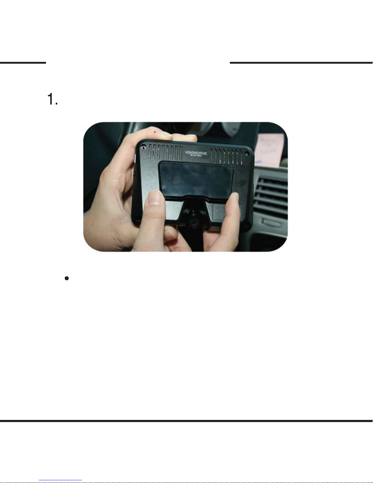
Connect the bracket and the unit
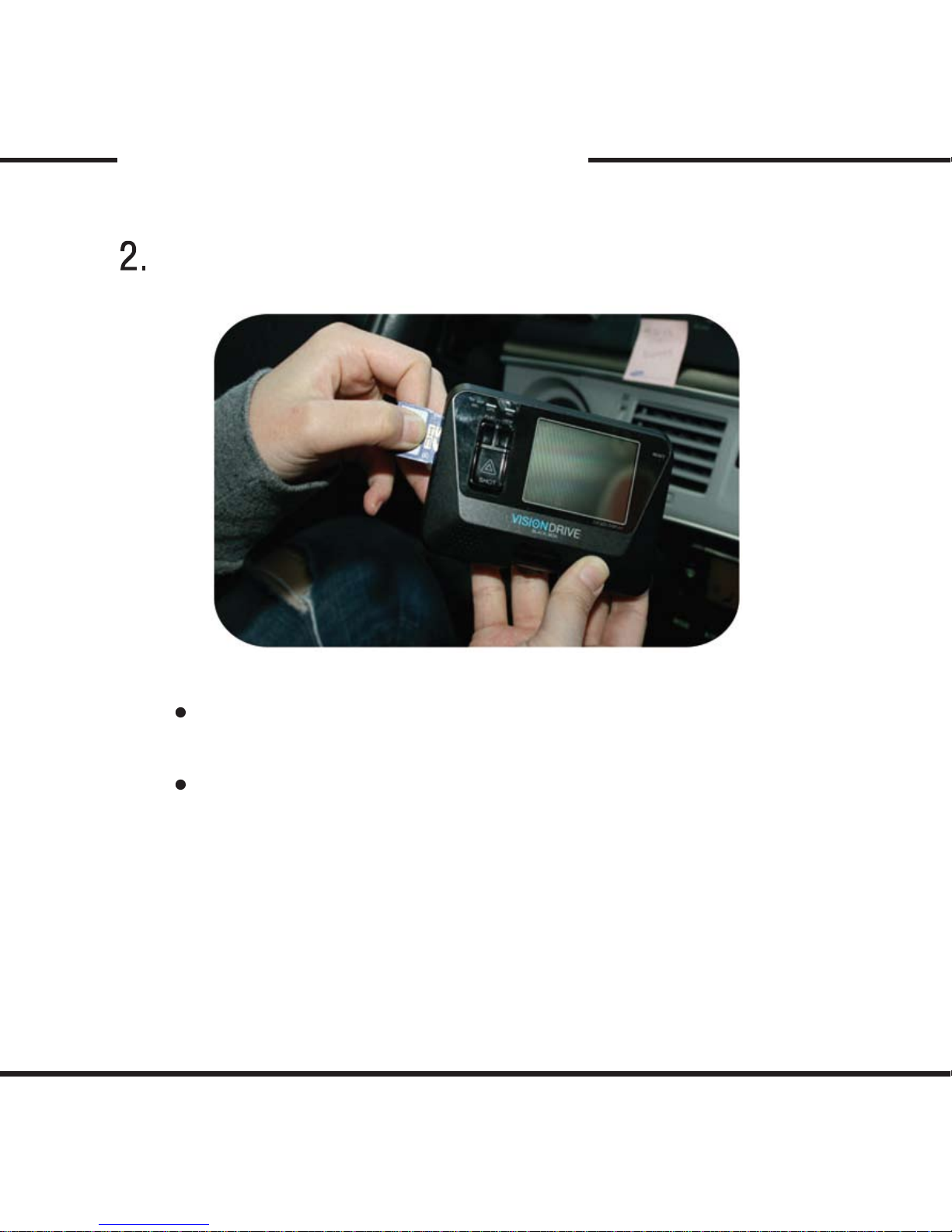
Insert SD card into the unit
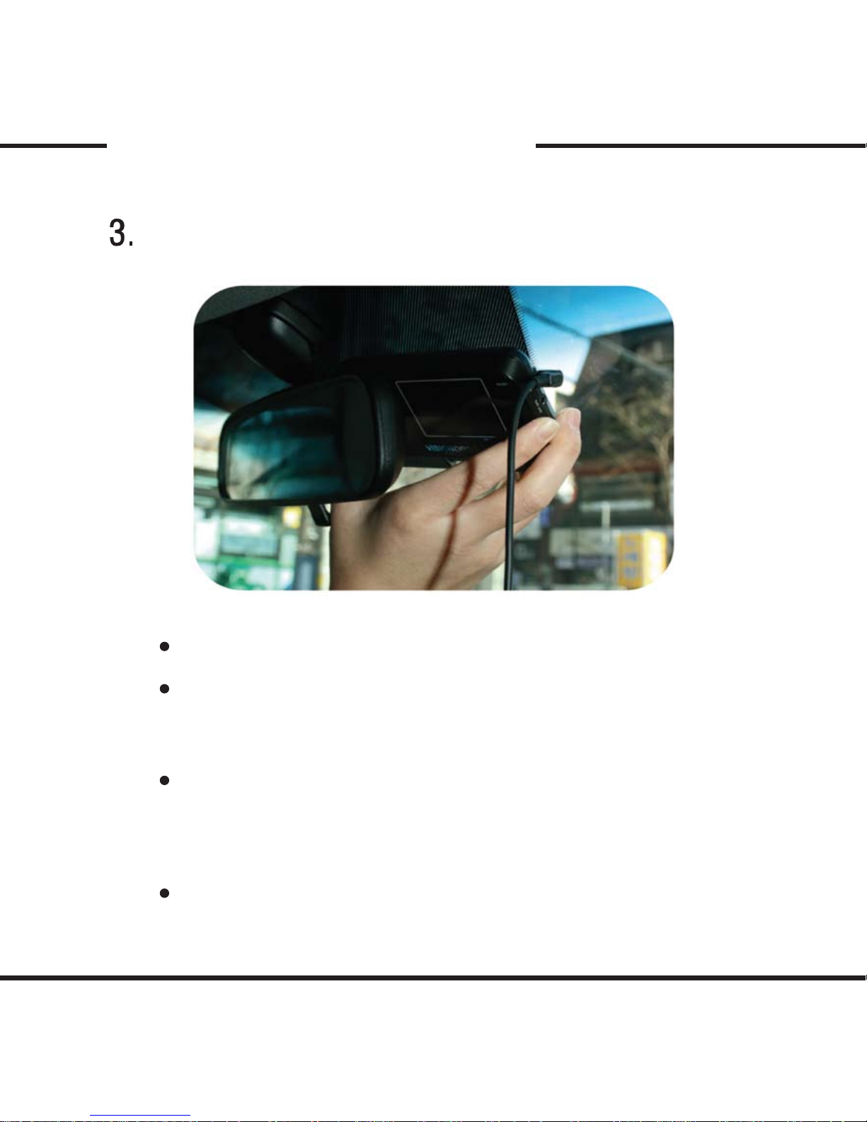
Connect cable and attach on windshield
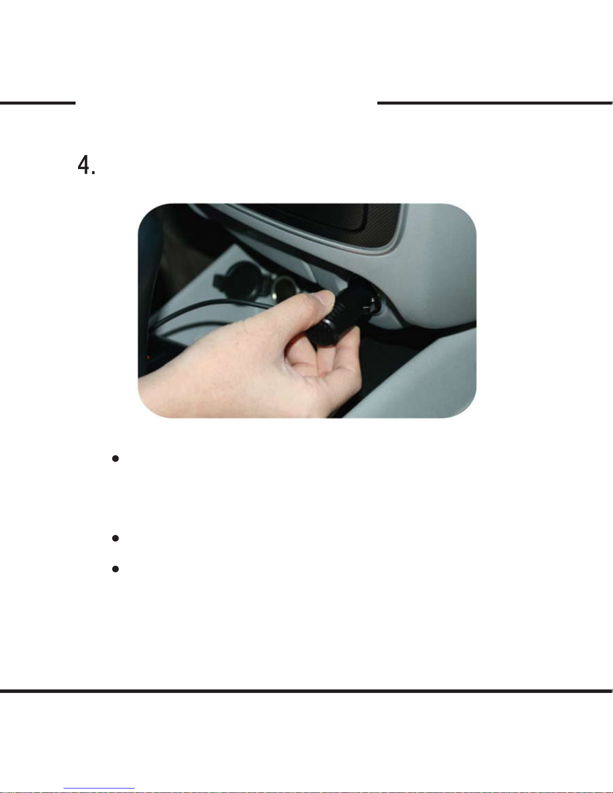
Connect to power source and turn on the unit
Adjust the camera angle
Check LED lamps
Organize cable line
Page 12
11
Installation Procedure
Connect the bracket and the unit
Place the bracket inside the groove of the unit then slide the bracket to
the left to click on.
(To remove the unit from the bracket, slide the unit to the left.)
Page 13
12
Installation Procedure
After connecting the bracket and the unit, insert the SD card as shown
above in the picture.
When ejecting the SD card from the unit, turn o the main power
completely, and then push in the SD card. The SD card will pop out when
pushed in.
Use of force or other methods to eject the SD card may defect the SD card.
Insert SD card into the unit
Page 14
13
Installation Procedure
Connect cable and attach on windshield
Connect to the cigar jack after all the cable is connected and the attachment
is nished with the unit.
The adhesive on the bracket is very strong. Partially remove the cover of the
adhesive, and then use the full adhesive part later for place adjustment.
For models with LCD, connect the unit to the power source then proceed
to attach to the windshield.
For the placement of the unit, it is better to place the unit closer to the
center of the vehicle. If the unit is installed on the right side of the back
mirror, make sure there is room to detach the unit if needed.
Clean the area on the windshield where the unit will be installed.
Page 15
14
Installation Procedure
Connect to power source and turn on the unit
Insert the cigar jack into an appropriate outlet then turn on the engine.
When the power is on, the LCD screen will turn on and a voice notication
will be announced.
Do not turn o the power source while the system booting is in
progress. This can damage the product.
Blinking of LED lamps noties that the system booting has ended.
Page 16
15
Installation Procedure
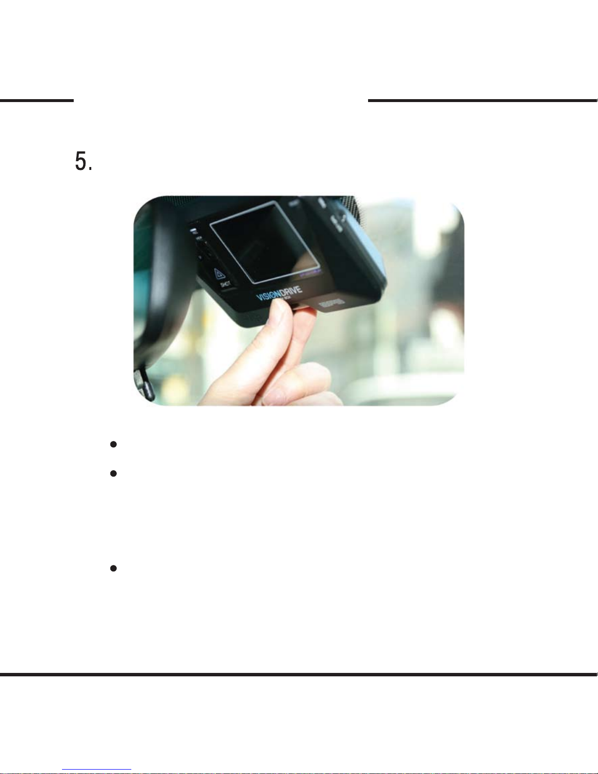
Adjust the camera angle
Move the camera top to bottom to x it to a recordable position.
Press [VIEW] button to see the view xed on by the camera using the
LCD screen.
After the camera position has been decided, press [VIEW] button
again to turn o the viewing on the LCD screen.
Recording is available while the LCD screen is on.
For certain vehicles, there are restrictions on GPS signals due to metal coating
on windshield or by the placement of the antenna on the vehicle. In such
cases, purchasing a seperate GPS module to be installed ourside of your
vehicle to have full GPS signals available for your recorded data.
Page 17
16
60’
Installation Procedure
Bracket
Unit
Camera
Vehicle Exterior
Highest
Position
Lowest
Position
Vehicle Interior (Driver’s Side)
Windshield
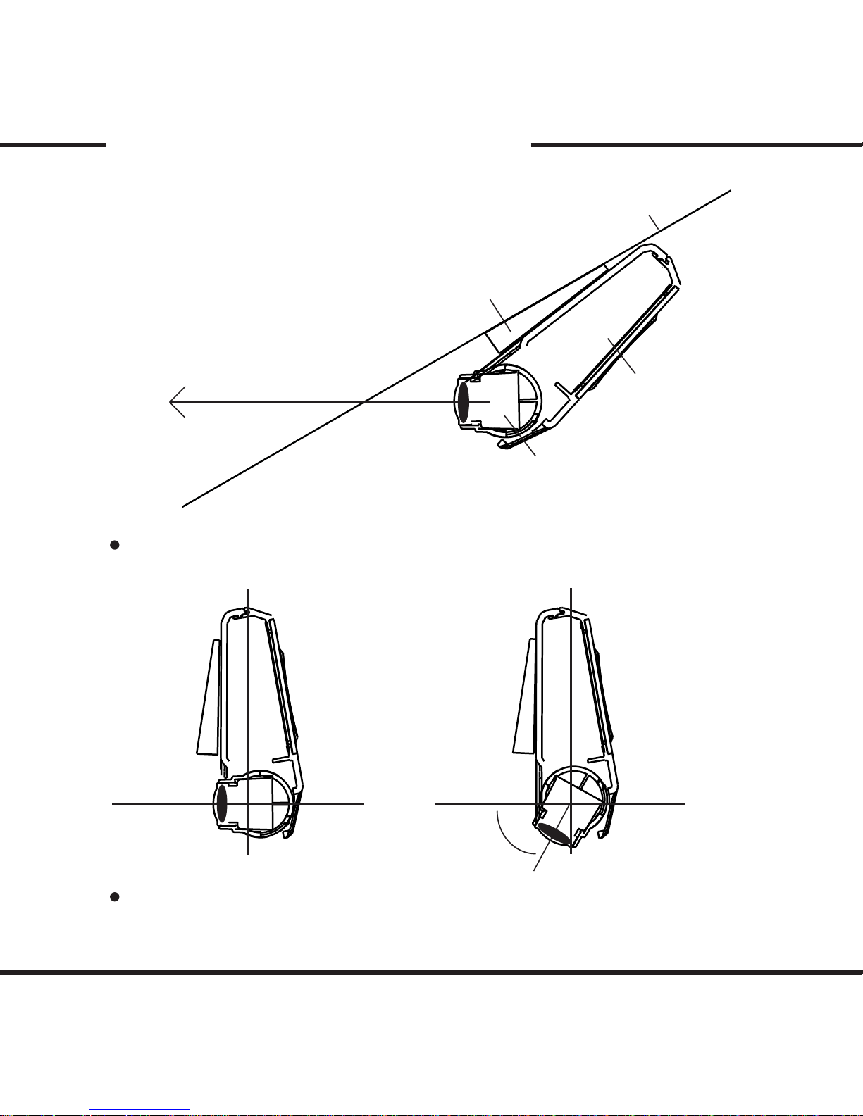
When the unit is attached, set the camera to face the front direction of the vehicle.
Camera can be rotated to 60 degree.
The camera rotation is set tightly to prevent loosening by minor impacts to
the vehicle, so place enough pressure to set the camera angle for adjustment.
Page 18
17
Installation Procedure
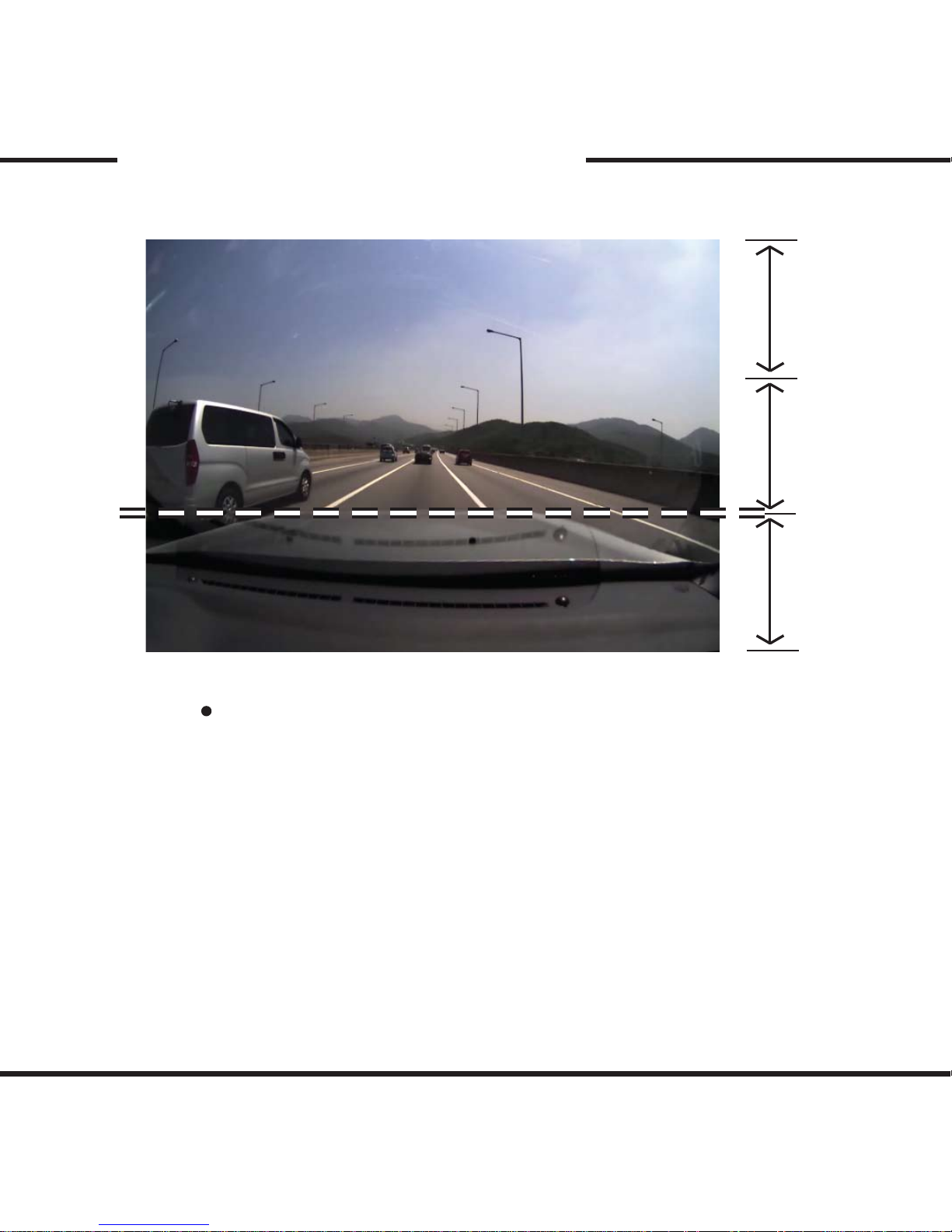
While viewing the LCD screen or analysis program, the dashboard
of the vehicle should be showing within 1/3 of the screen.
Page 19
18
Installation Procedure
Check LED lamps
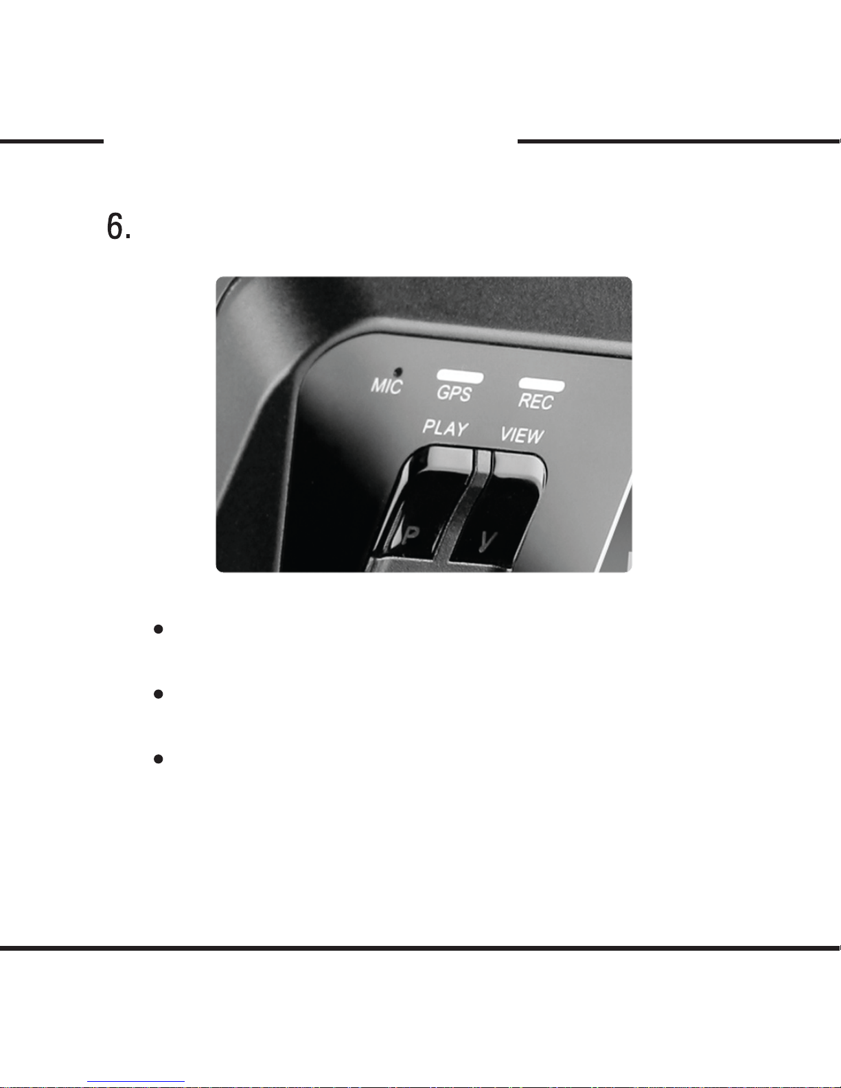
The GPS lamp is red when the GPS signal is not connected and blue when
it is connected.
The GPS connection may take up from a couple of seconds to several
minutes, depending on the location of the vehicle.
The REC lamp is blue when it is recording a (NORMAL) le and red when
recording into an (EVENT) folder due to an impact.
Page 20
19
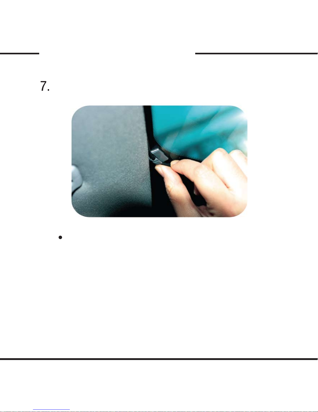
Organize cable line
Installation Procedure
Use the enclosed cable holders to organize the cable line.
Page 21

20
Product Use
Start up
- Turn o the engine and remove the key from ignition.
- Check to see if the SD card is inserted into the unit.
- Turn on the engine
- When the engine is turned on, the system booting starts with the program
installed in the SD card and a voice notication will be announced.
(LCD screen will turn on and show the view xed on the camera for a
few seconds and then will turn o. If you would like to record while the
LCD screen is on, press [VIEW] button.)
- Then the REC and GPS lamps will start to blink.
- The REC lamp will turn blue while blinking.
- The GPS lamp will turn red if not connected and blue if connected.
- The GPS connection may take up from couple of seconds to several minutes,
depending on the location of the vehicle.
Page 22

21
Product Use
Normal Recording and Event Recording
- While the power is on, the normal recording is on as well. The REC lamp will
be blinking blue.
- In normal recording mode, les will be recorded into 5 minutes intervals and
sent to the (NORMAL) folder. If the memory is full while the normal recording
is on, the program will erase the oldest recorded data then record the new
data.
- In the case of an impact, the sensors will trigger the event mode. An alarm will
sound to notify the user. The REC lamp will be red and the recorded data will
be saved in (EVENT) folder.
- When the event data is stored, the program records 10 seconds prior to the
impact and up to 60 seconds after the impact. These time settings can be set
manually by using the analysis program when the SD card is connected to
the PC.
- The memory division between the event and the normal recording mode can
be set within the analysis program. Also, the resolution of the recorded data
and sensor settings can be changed within the analysis program.
Page 23

22
Product Use
Manual Recording
- When the [SHOT] button is pressed, the alarm will sound and the recorded data
will be saved in the (EVENT) folder.
- Even though impacts cause the black box to automatically record event les,
the [SHOT] button can be used to record other accidents of others or can be used
to record great scenery while traveling.
- Even while the [PLAY] button is in function, pressing the [SHOT] button will
initiate an event recording.
Page 24

23
Product Use
Viewing
- Press the [VIEW] button to view the scene that the product is recording.
- Pressing the [VIEW] button again will turn o the LCD screen. The
normal recording is still in process while the LCD screen is o.
- Park your vehicle in a safe place before changing your view mode.
Page 25

24
Product Use
Parked Surveillance Mode
- While parked, hold the [PLAY] or the Function [I] button for 3 seconds,
a voice notication will notify that the parking mode has been
initiated.
- In parking mode, even the slightest impact or vibration will be
picked up by sensors and the sensor setting will automatically be changed.
- In parking mode, without any impact, the recorded data will be 4 frames
per second. With an impact, all settings will be back to the event mode
and after the recording is done, the system will get back to the parking mode.
- The parking mode does not record sounds.
- To clear the parking mode, press the [PLAY] button for 3 seconds.
A voice notication will notify that the continous recording will start.
- To use the parking mode, the product has to be connected to the power
source directly. In regards to directly wiring to the vehicle’s power source,
we recommend using professional help and to connect it from interior
wiring for lightings within the vehicle.
- Extensive use and the continuous usage of the vehicle’s power source may
exhaust the performance of the product. The company is not liable for the eects
of continous use of the product more than 24 hours. We recommend the full
power to be o between uses of 2 to 3 days to maintain the product for longer
use.
Page 26

25
Product Use
SD Card Use
- The Vision Drive product will only work with the SD card issued from
Vision Drive. VD SD cards carry programs necessary to operate the product in
full. Also, the provided SD card is tested and certied by Vision Drive and other
SD cards may come short to the technology and development VD SD
cards can oer.
- To eject the SD card from the product, the engine has to be turned o and
the key should be removed from the ignition. After the few seconds the key has
been removed, the product will turn o automatically and the LED lamps will
be turned o as well. The interior EDLC allows the last images to be stored
into proper folders before the product is fully turned o.
When both the LCD screen and LED lamps are turned o, remove the SD card.
- When the SD card is removed, it needs to be reinserted before the vehicle
is in motion again. Without the correct SD card, the product will not function
properly.
- Use only SDHC supporting SD card readers to read the SD card.
- If a wrong or defected SD card is inserted, a voice notication will ask
for a correct SD card to be inserted. If the same card is used and the same
notication is given multiple times, purchase a replacement.
- When the tap is xed to close on the SD insertion slot, a voice notication
will notify you. Reset the tap to open it, and then insert the SD card into the slot.
- If a voice notication repeatedly announces to insert a correct SD card,
then the SD card is defected or damaged. Purchase a replacement.
- The SD card readers can be purchased seperately at most computer
accessory stores or sites.
Page 27
26
Product Use
Event File Replay
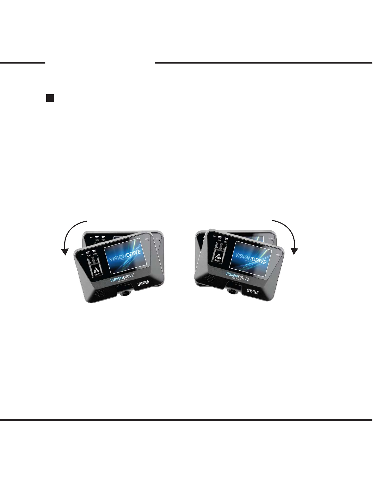
- When the [PLAY] button is pressed, the last event store will be played.
- While play mode is on, if you press the [VIEW] button or if you tilt the unit
to the right like the demonstration below, the le prior to the most recent data
is played.
By pressing the [VIEW] button multiple times or by tilting the unit to the
right, you can search for the data you are specically looking for.
(If the unit is tilted to the left, you can view from newer datas.)
- Press the [PLAY] button again to turn o the play mode and to start normal
recording mode.
Page 28

27
Product Use
Voice Recording
- When the [SHOT] button is held for more than 3 seconds, the voice
notication will announce that the voice recording will initiate and the voice
recording will start.
- When the [SHOT] button is held again for more than 3 seconds, the voice
notication will announce that the voice recording has been stopped.
- The initial setting can be changed from the analysis program on your PC.
Page 29
28
Product Use
Automatic System Check and Safe Rebooting Function
- This product is programmed to automatically check and reboot the system,
if the product is in a non-functional status. By rebooting the system from
the program installed on the SD card, the product can notify that such action
is being taken place to the user while it is happening.
- By having the safeguard of the system in such ways, the
stability of the system is ensured. If the reboot is happening too often, the
program installed in the SD card may have been manipulated .
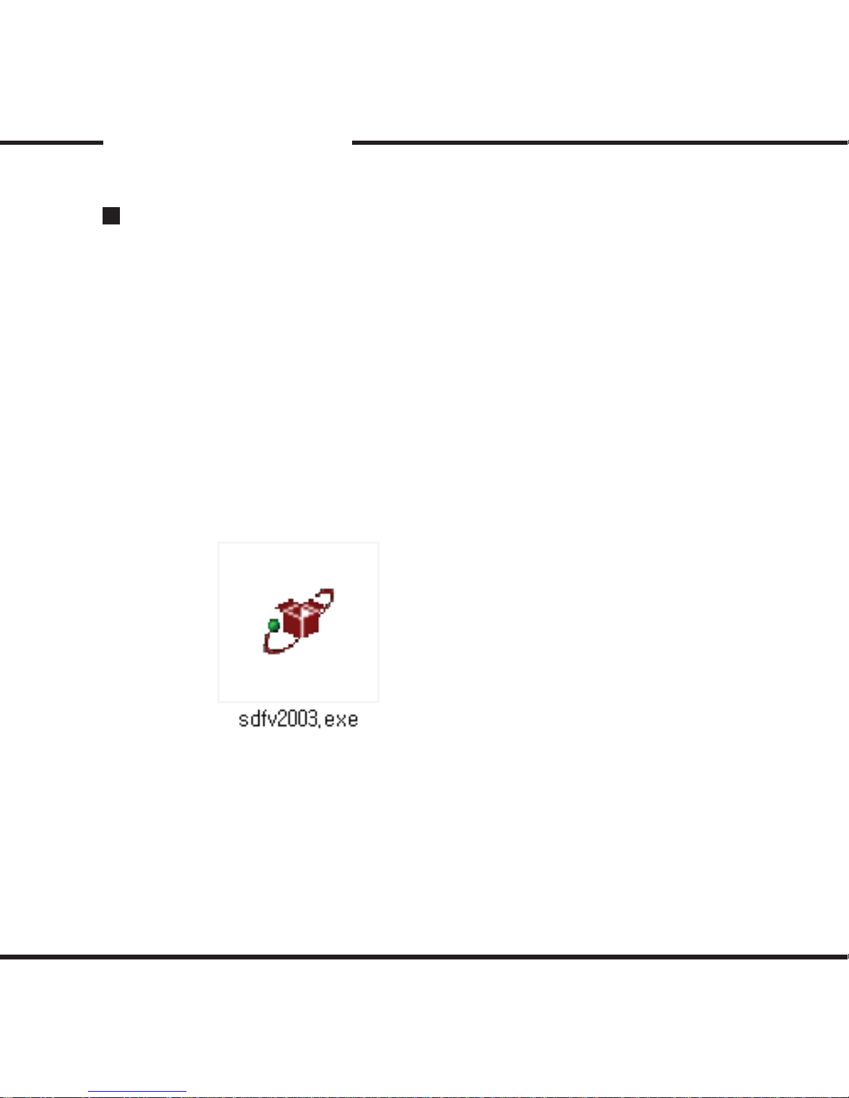
Use the format program within the SD card, sdfv2003.exe, to reformat the
SD card.
Page 30
29
PC Analysis Program Use
*** The skin used for the analysis program may vary by the version ***
Program Start Up
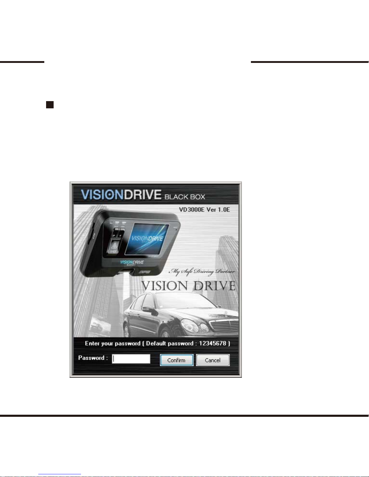
- After the SD card is connected to the PC, open up the VDAnalyzer.exe le.
- The initial and default password is “12345678”.
However, you can change the password settings after you are logged in..
Page 31
30
PC Analysis Program Use
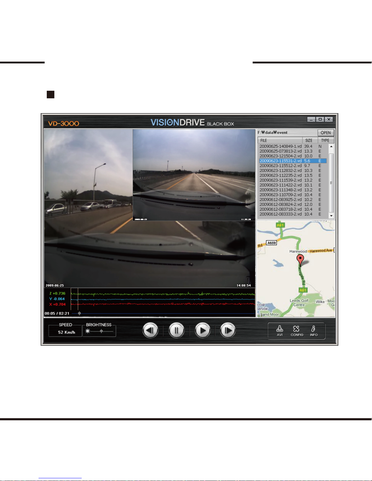
Program Information
Page 32
31
PC Analysis Program Use
How to play the les
- To play a certain le, select the le from the list located on the right side.
- The most recent data will be listed from the top.
- The (EVENT) folder will be the default folder that will show when you rst open up
the program. In the (EVENT) folder, all data recorded due to an impact or by pressing
the [SHOT] button will be present.
- The (NORMAL) folder will have normal recording data and you may view them
by clicking “open” on the analyzer.
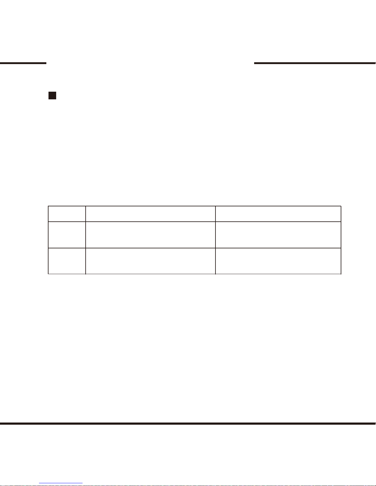
- The names of the les are composed as the table below.
(No. separation for recording: 1-Normal, 2-Event)
- Number separation is divided into two groups - 1 and 2. 1 is for normally
recorded data and 2 is for recorded events.
- The date is set as Year/Month/Day.
- Time is set as Hour/Minute/Second
- NOGPS is used when the GPS signal has failed to connect. The GPS signal may
become disconnected, depending on where the vehicle was while the recording
was made.
GPS
Failed GPS
Separation Actual File Name (Search Window) Viewer File Name (Analyzer’s List)
Password-Date-Time-No. Seperation
(EX.) 12345678-20090102-120102-1
Password-NOGPS-Password-No. Seperation
(EX.) 12345678-NOGPS-12345678-1
Date-Time-Numeral Seperation.vd
(EX.) 20090102-120102-1.vd
NOGPS-Password-Numeral Seperation.vd
(EX.) NOGPS-12345678-1.vd
Page 33
32
PC Analysis Program Use
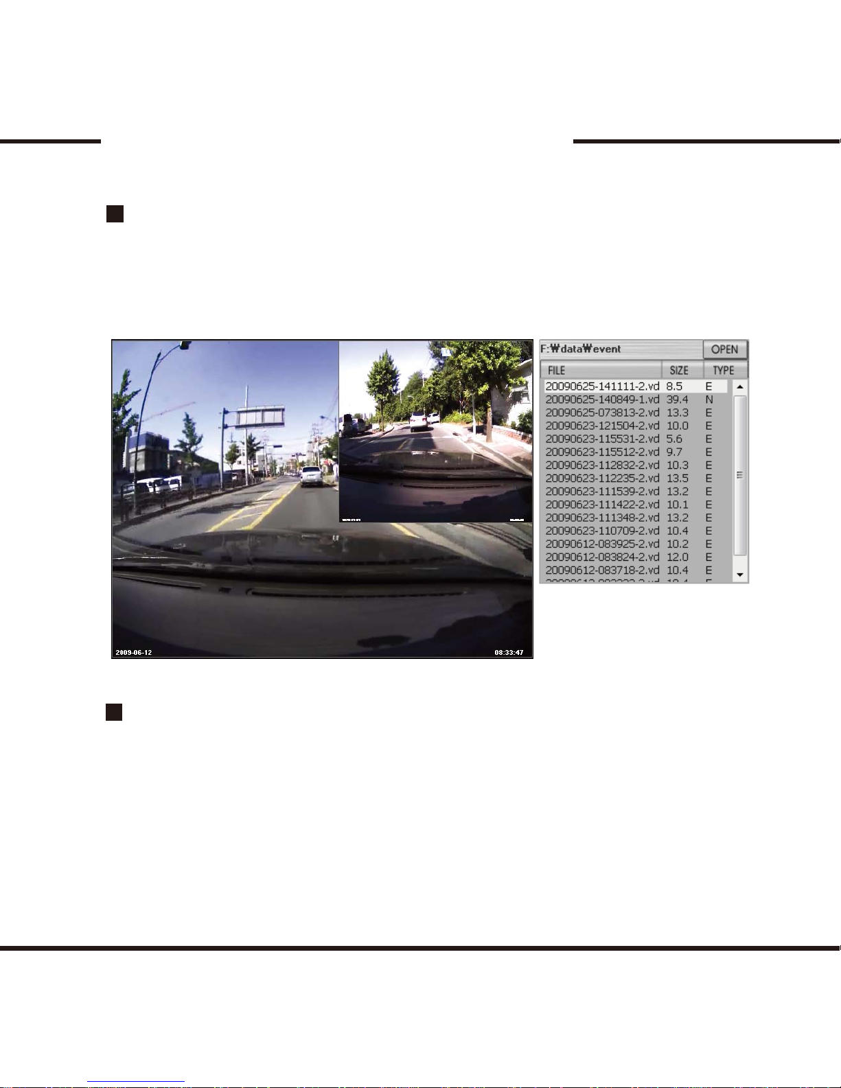
Preview Function
Auto-play Function
- When a le is selected, a preview of the rst frame of the data is shown on the
screen, as shown in the sample below. This helps to select a le with ease and less
confusion. When the le on the list is double clicked, the le will play.
- After you double-click a le, the recordings will automatically and continuously
play one after another.
The last le of the list is connected to the top and will automatically
continue; when the last le is played it will return to the rst le on the list.
However, the (EVENT) and (NORMAL) folders are not continously connected
with each other. Each folder has to be open separately.
Page 34
33
PC Analysis Program Use
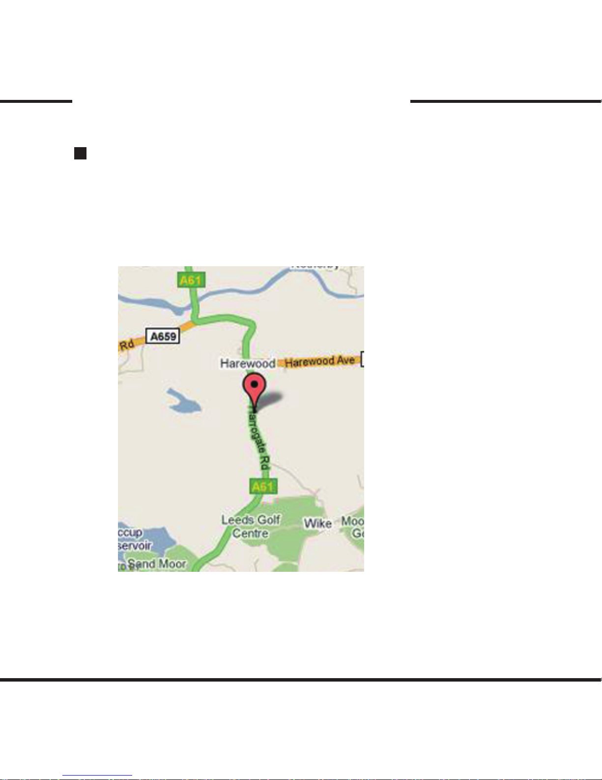
Interworking with the map
- With the GPS data, the map shows the location of the vehicle while
playing the recorded data.
- The map is viewable only on the analyzer.
- Google map is used.
Page 35
34
PC Analysis Program Use
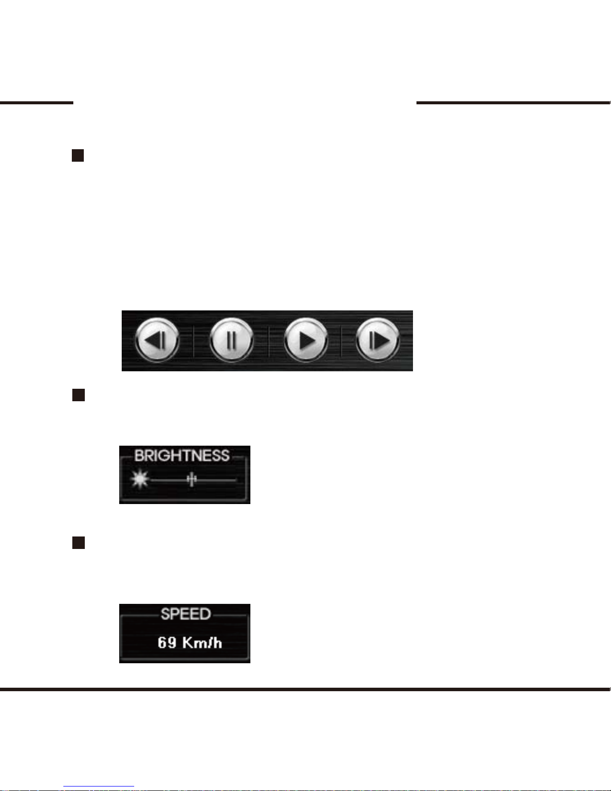
PLAY / PAUSE / PREVIOUS FRAME / LATTER FRAME
BRIGHTNESS CONTROL
SPEED METER
- When the play button is pressed, it will replay the video le shown on the screen.
When selecting a le from the list, double click the le from the list
to play the le.
- When the pause button is pressed, the previewing data will be paused.
- When the previous frame and the latter frame button is pressed, it will move
between frames within the le. It does not move from one le to another. To do
so, pause the the le that is being viewed, and then use the frame buttons to
move between frames.
- Use the bar to set the brightness to help view the le.
- While the le is being played, the speed meter will show the vehicle’s speed
that was collected by the GPS.
Page 36
35
PC Analysis Program Use
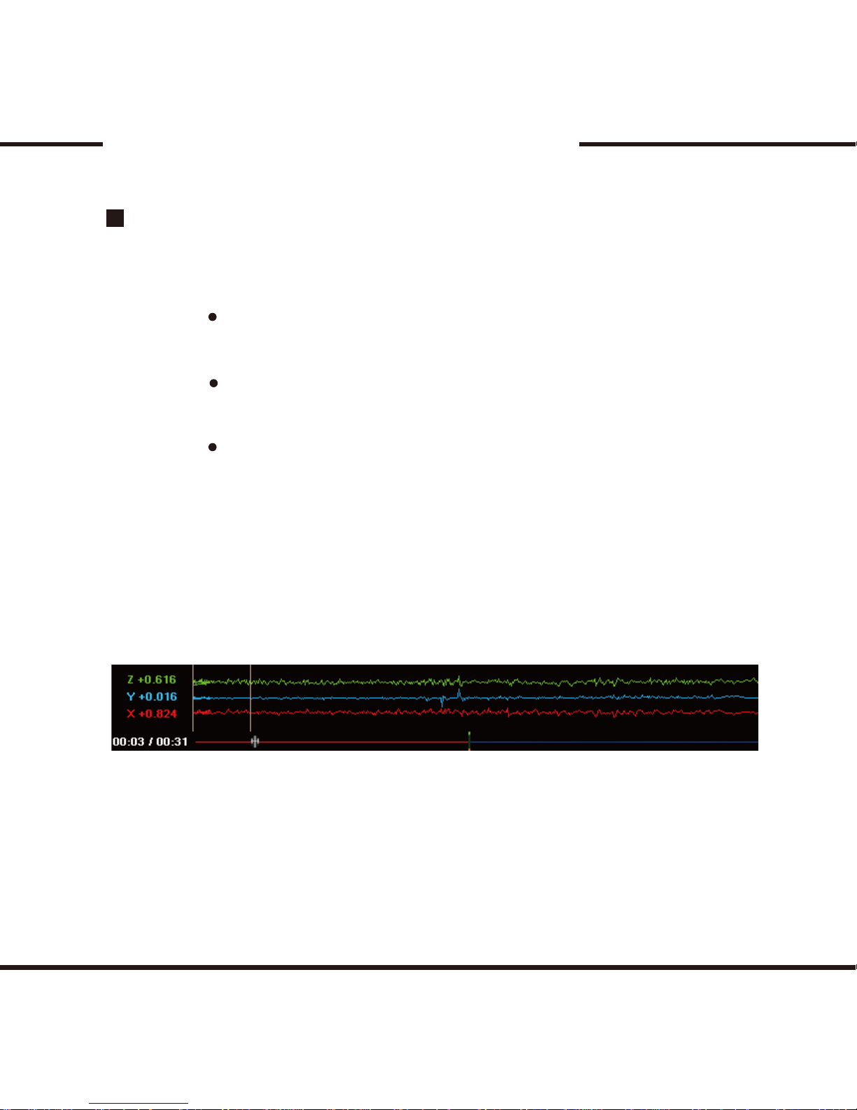
G Sensor / Shock Sensor Graph
- The graph below shows impacts on the xyz axises of the vehicle.
- The bottom left shows the total time of the impact.
- Each impact will be noted as jolts or jerks in vertical lines within the axis.
(Like a heart monitor)
X axis : measures and records
impact from the front and back of the vehicle
(From 0G to 3G is recorded)
Y axis: measures and records
impact from the left and right sides of the vehicle
(From 0G to 3G is recorded.)
Z axis: measures and records
impact from the top and lower part of the vehicle
(From 0G to 3G is recorded.)
Page 37
36
PC Analysis Program Use
Converting to AVI le
- The data les in the SD card are Vision Drive les and will
only work within VDAnalayzer program.
- To view the data on a regular PC without having the analysis program within
the SD card, the VD le has be be converted to an AVI le.
- Pause the le where you want the conversion to take place on the previewing
le.
- Press the AVI conversion button on the bottom right side, and then a window
will pop up to have the le renamed.
- You may put any name you would like. There is no need to put .avi on the end.
- Press the play button again, and then the data being previewed will be
converted from the point you specied.
- When you press the pause button while the conversion is in progress, the
conversion stops from that point.
- If the necessary codec is not available to convert the data into an avi le, it may
not work on your PC or a notication will pop up saying you may need to
download needed codec to proceed. In such cases, use Xvid-1.2.1-0412008.exe
to install the needed codec, then restart the analyzer program to proceed again.
If the codec is already installed on the PC, there may be some diculties
if the codec is installed twice. So unless there is a notication for installing
a codec, do not install.
Page 38
37
PC Analysis Program Use
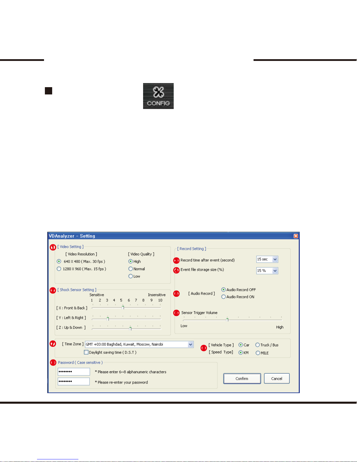
Conguration
- The video resolution and quality settings can be congured.
- If the resolution is high, the le’s size also becomes larger and will
take more memory on the SD card.
- The sensor can be congured. If the number is larger on the sensor, the
sensor becomes less sensitive and if the number is lower, the sensor will be
heightened.
- The time setting for recording after the impact can be congured.
The recording time prior to the impact is 10 seconds.
- If you set the % for the (EVENT) folder, the rest of the memory will be assigned
to the (NORMAL) folder.
- The voice recording and the impact alert setting can be congured.
- New passwords can be set to be used for private or corporate use.
①
②
③
④
⑤
⑥
⑦
⑧
⑨
Page 39

38
Warranty
The warranty is for 1 year from the date of purchase. If the product
malfunctions on itself under normal use, you can have the product repaired .
To apply for warranty, register your product with your information
Only registered products will be submitted for repair or service.
If the warranty period expires, repairs and services can be provided only if
paid by the purchaser of the product.
In below cases, the repairs may be subjected to payment by the user.
- If the product has been remodelled or disassembled or has been damaged
due to use against the product’s normal usage
- Damages due to environmental crisises such as earthquakes, thunderstorms,
etc.
- Using other cables that were not provided by the company and were not
enclosed with the unit.
- Dropping or damaging the product by fault of the user.
Warranty repairs are available only in the country where the product is
bought.
Page 40
39
VISIONDRIVE VD-3000
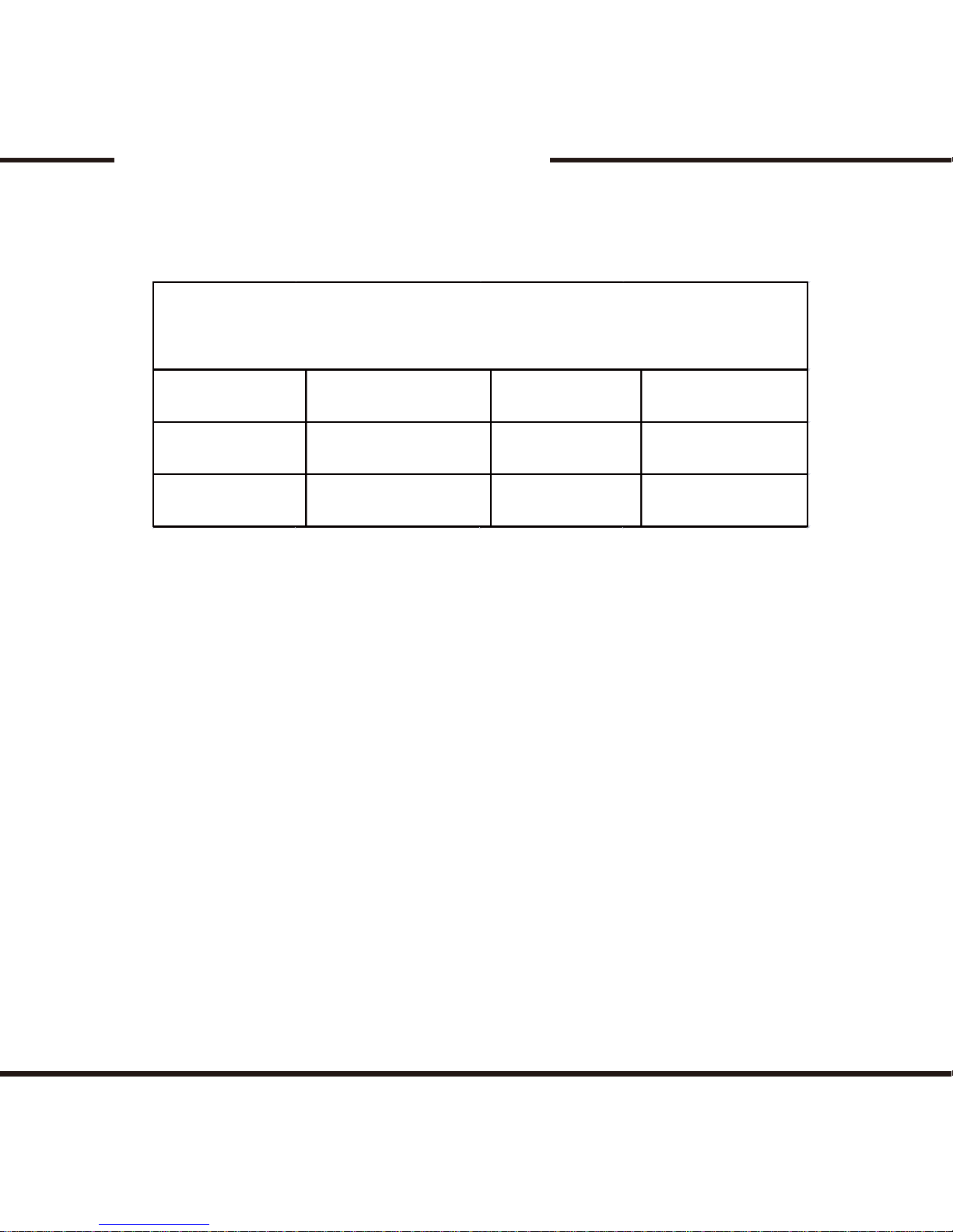
Warranty Certicate
Warranty Certicate
Product Name
Purchase Date
Retail Shop
Model Name
Serial Number
Warranty
Period
If the product malfunctions after the 1 year warranty period expires,
no service is provided under warranty. If the certicate does not have
the date of purchase, the 1 year warranty is calculated by the serial
number’s production date plus an additional 1 month to calculate the
1 year warranty period.
- The Vision Drive company will follow Consumer Protection Act (1006-36)
to give warranty to all the products sold to consumers in the available regions.
- A decline of the warranty coverage will be notied to the consumer after 14 days
of the application. If the application is accepted, the coverage will be in
full eect within 30 days.
- This product’s warranty period is 1 year from the date of purchase.
Page 41

40
All hardwares, softwares, design and logo of the product is
copyrighted by the manufacturer of the product.
Copy, disassembly, remake and distribution without the manufacturer’s
consent is prohibited and will be enforced by all legal rights held by
the manufacturer.
Page 42

CAR BLACK BOX
TM
 Loading...