


Cam SS XP
Digital Video Recorder (DVR) Workstation
(Version 1.04)
User Manual
Rev10-18-2002
Information contained in this document is subject to change without
notice.
All rights reserved. © 2002

1
FCC (Federal Communication Commission) Notice
This equipment has been tested and found to be in compliance with the
criteria for Class B digital devices as referred in Part 15 of the FCC
Rules. The FCC Rules are designed to provide reasonable protection so
that an equipment complying with those criteria will not cause harmful
interference when installed indoors. This equipment may generate
radio frequency energy and, if not installed in accordance with
instructions, it could cause harmful interference to wireless
communications. However, certain installation in special way may also
cause interference. If this equipment causes interference to the
reception of radio and television, users shall eliminate the interference
by using any or several of the following measures:
■ Reorient and relocate the receiving antenna.
■ Increase the distance between the equipment and receiver.
■ Connect the equipment to an outlet on a different branch circuit
from the receiver
■ Seek help from a dealer or an experienced radio/TV technician.
All Rights Reserved © 2002 Vision Controls Corp.
Windows 95?Windows 98?Windows ME?Windows 2000?Windows XP
and Words are the trademarks of Microsoft Corporation;
Other trademarks and trade names may be used in this document to
refer to either the entities claiming the marks and names or their
products.

2
INTRODUCTION
Cam SS XP Surveillance System is an all-in-one system that integrates
various functions including monitoring, alarming, controlling, remote
monitoring, video recording and playing. Cam SS XP transfers recorded
image signals into digital signals and after compression saves those files to
the hard drive on that PC. With many years’ efforts, we have successfully
applied SMC (Super Motion Compression) to this system.
Although the SMC (Super Motion Compression) provides the extra high
image compression ratio, the image quality is not affected because of the
increased compression ratio. Small volumes of data enable it to transmit
images through limited bandwidth (narrow band) transmission media (e.g.
MODEM) at a better performance than normal. SMC may be currently the
only image compression technology specifically developed for the security
market.
Cam SS XP system has the following features:
■ SMC (Super Motion Compression) with high video compression ratio
provides superior image quality with extended available recording
time.
■ Adjustable image sensitivity, quality and recording speed.
■ Image data can be striped across multiple hard drives on a single
computer.
■ Provides up to 9 audio channels per system to be used for synced
audio recording.
■ Intelligent real-time motion detection and alarm functions.
- Adjustable sensitivity of motion detection
- Motion detection triggering local alarm
- Motion detection triggering remote alarm (dialing out to a telephone,
a pager or a remote Cam SS XP system)
■ Individual alarm settings for each camera
■ Programmable alarm schedules for each camera.
■ Alarm log
■ Scheduled recoding
■ Recyclable recording
■ Quick search for stored video files
■ Multitude of playback functions
■ The following functions may be performed through PSTN, LAN,
Internet or Intranet: remote monitoring, video recording, PTZ control,
output port control, searching and downloading video files.
■ Create snapshots during recording, playback or remote monitoring.
■ Output port (Device) control and input port (Sensor) detecting.
■ Control of the traditional PTZ and high speed dome cameras.
■ Dome Camera: preset control

3
■ Dome Camera: auto-pan control
■ Dome Camera: cruise of preset positions (with programmable dwell
time at each preset position)
■ Input sensor triggered preset position panning of the dome camera.
■ Video Lost Alarm.
■ Superb multi-functions:
- Simultaneous remote monitoring and control of a different remote site
- Simultaneous remote monitoring and control by a different remote
site
- Simultaneous receiving of different camera triggered alarms
- Simultaneous playing of several video files
- Simultaneous viewing of several pictures
- Simultaneous performance of all the foregoing functions
■ Clipping of video files
■ Hiding the recording screen
■ Password protection
■ Automatically start recording video upon boot.
■ Automatically shut down the computer when system supervisor
closes the Cam SS XP program.
INTRODUCTION ............................................................ 2

4
Chapter 1: Installation............................................. 9
1.1 Installing the Cam SS XP Application Software.................. 9
1.2 Uninstalling the old Cam SS version.................................10
Chapter 2: System Overview .................................11
2.1 Starting Cam SS XP.........................................................11
2.2 Main Screen ....................................................................12
2.2.1 Image Section..................................................................12
2.2.2 System Functionallity Section...........................................13
Chapter 3: System Setup ...................................... 20
3.1 Board Setup.....................................................................21
3.2 Camera Setup..................................................................22
3.3 Host Setup.......................................................................23
3.4 Users...............................................................................26
3.4.1 New User Setup...............................................................27
3.4.2 Editing User.....................................................................28
3.4.3 Delete User......................................................................28
3.5 Database Setup...............................................................29
3.5.1 Adding A New Database...................................................29
3.5.2 Editing a Database Entry..................................................30
3.5.3 Deleting a Database Entry ...............................................30
3.6 Sound Bank.....................................................................31
3.6.1 New Sound......................................................................31
3.6.2 Edit..................................................................................32
3.6.3 Delete..............................................................................32

5
3.6.4 Preview............................................................................32
3.7 Address Book ..................................................................33
3.7.1 Adding a New Entry to the Address Book.........................33
3.7.2 Edit..................................................................................35
3.7.3 Delete..............................................................................35
3.8 Program Setup (Scheduled Recording)............................35
3.8.1 New Recording Schedule.................................................36
3.8.2 Edit Program....................................................................38
3.8.3 Deleting a recording schedule..........................................38
3.9 I/O Devices......................................................................38
3.10 Emap...............................................................................39
Chapter 4: Recording............................................ 46
4.1 Recording Windows.........................................................46
4.1.1 Activate Recording of Cameras ................................46
4.1.2 Inactivate Recording of Cameras..............................46
4.1.3 Camera Status Display.....................................................46
4.1.4 Caption......................................................................47
4.1.5 Caption color..............................................................47
4.1.6 Unmask Motion Detection Area ..................................48
4.1.7 Snapshot....................................................................48
4.1.8 Video Configuration....................................................48
4.2 Recording Setup..............................................................48
4.2.1 Camera Setup..................................................................48
4.2.2 Mode...............................................................................51
4.2.3 Motion Detection Setup....................................................52

6
4.2.4 PTZ control select............................................................53
4.2.5 Alarm setup .....................................................................53
4.3 Preview............................................................................53
Chapter 5: Playback .............................................. 54
5.1 Video Playback ........................................................54
5.1.1 Parameter Mode..............................................................54
5.1.2 File Mode.........................................................................55
5.2 Video File Playback .........................................................57
5.2.1 Stop ...........................................................................58
5.2.2 Play............................................................................58
5.2.3 Pause.........................................................................59
5.2.4 Backward Search.......................................................59
5.2.5 Forward Search.........................................................59
5.2.6 Forward with single Image.........................................60
5.2.7 Backward with single Image.......................................60
5.2.8 Snapshot................................................................60
5.2.9 Start Video Clip.......................................................60
5.2.10 End Video Clip........................................................60
5.2.11 Save the Video Clip................................................60
5.2.12 Playback clip..........................................................60
5.2.13 Caption...................................................................61
5.2.14 Caption Color.........................................................61
5.2.15 Zoom In.....................................................................61
5.2.16 Zoom Out..................................................................61
5.2.17 End............................................................................61
5.2.18 Fast and slow playback..................................................61

7
5.3 Load picture / Print picture ...............................................62
Chapter 6: Alarms.................................................. 63
6.1 Alarm Setup.....................................................................63
6.1.1 Alarm Event Period..........................................................64
6.1.2 Activate condition.............................................................64
6.1.3 Alarm Actions...................................................................64
6.2 Alarm Log ............................................................72
Chapter 7: I/O Device............................................. 73
7.1 I/O Device Setup..............................................................73
7.1.1 Selecting the desired I/O device.......................................73
7.1.2 Adding an I/O device........................................................74
7.1.3 Editing I/O Device............................................................74
7.1.4 Deleting an I/O Device.....................................................74
7.1.5 Setting up an I/O Device ..................................................75
7.2 PTZ Control Panel ...........................................................80
7.2.1 Direction Control..............................................................80
7.2.2 Iris, Focus, Zoom Control.................................................80
7.2.3 Preset point function and setup........................................81
7.2.4 The Cruise Function and Setup........................................81
7.2.5 Auto Pan function and setup............................................82
7.3 Output Port Control..........................................................82
Chapter 8: Cam SS Server .................................... 83
8.1 Starting Cam SS Server...................................................83
8.1.1 A System Administrator ( System Supervisor)...................83

8
8.1.2 A common Cam SS Server user.......................................83
8.2 Cam SS Server Window...................................................83
8.2.1 Login / Logout..................................................................83
8.2.2 Adding a new user...........................................................83
8.2.3 Editing and deleting a user...............................................84
8.2.4 The Connection Contents.................................................85
8.2.5 Connecting to other Cam SS Server ................................85
8.2.6 Auto Start.........................................................................85
8.2.7 Shuting Down the Cam SS Server ...................................85
8.2.8 Exiting Cam SS Server ....................................................86
Chapter 9: Remote Access......................... 87
9.1 Remote Access Via TCP/IP..............................................88
9.2 Remote Access Via Modems............................................91
9.3 Remote PTZ and Output Port Control Functions...............93
9.4 Other Remote Access Functions......................................94
9.5 Remote Monitoring Only ..................................................94
9.6 Examples of remote connections......................................95
10.0 Additional Features Included in this Release………………97

9
Chapter 1: Installation
1.1 Installing Cam SS XP Application Software
■ Load the Windows operating system.
■ Put the Cam SS XP system CD into your CD-Rom drive.
■ After double clicking “My Computer”; double click the CD-ROM drive.
■ Double Click “Cam SS XP.exe”. The following installation picture will
appear on the screen.
■ Follow the instructions and select the Next button to continue the
installation.
Note:Installation programs will inform whether your computer
needs to restart after the installation.

10
1.2 Uninstalling the old version
Use Add/Remove Programs located in the Control Panel to remove the
previous version of Cam SS XP. Select the Cam SS XP on the
Add/Remove Program in the Control Panel. Then click the Remove(R)
icon to remove the Cam SS XP program.
The video files and directories are not actually removed during the
uninstall process, those directories created during the previous
installation still exist. The user may use go into C:\Program Files\Cam
SS XP (assume it is the directory selected in previous installation). Delete
those directories and files unless the user chooses to keep those
directories and the image files.
Note:In order to prevent abnormal execution of the new version of
Cam SS XP programs, it is recommended to delete all of the
associated files other than those subdirectories in the Cam SS
XP directory.
11
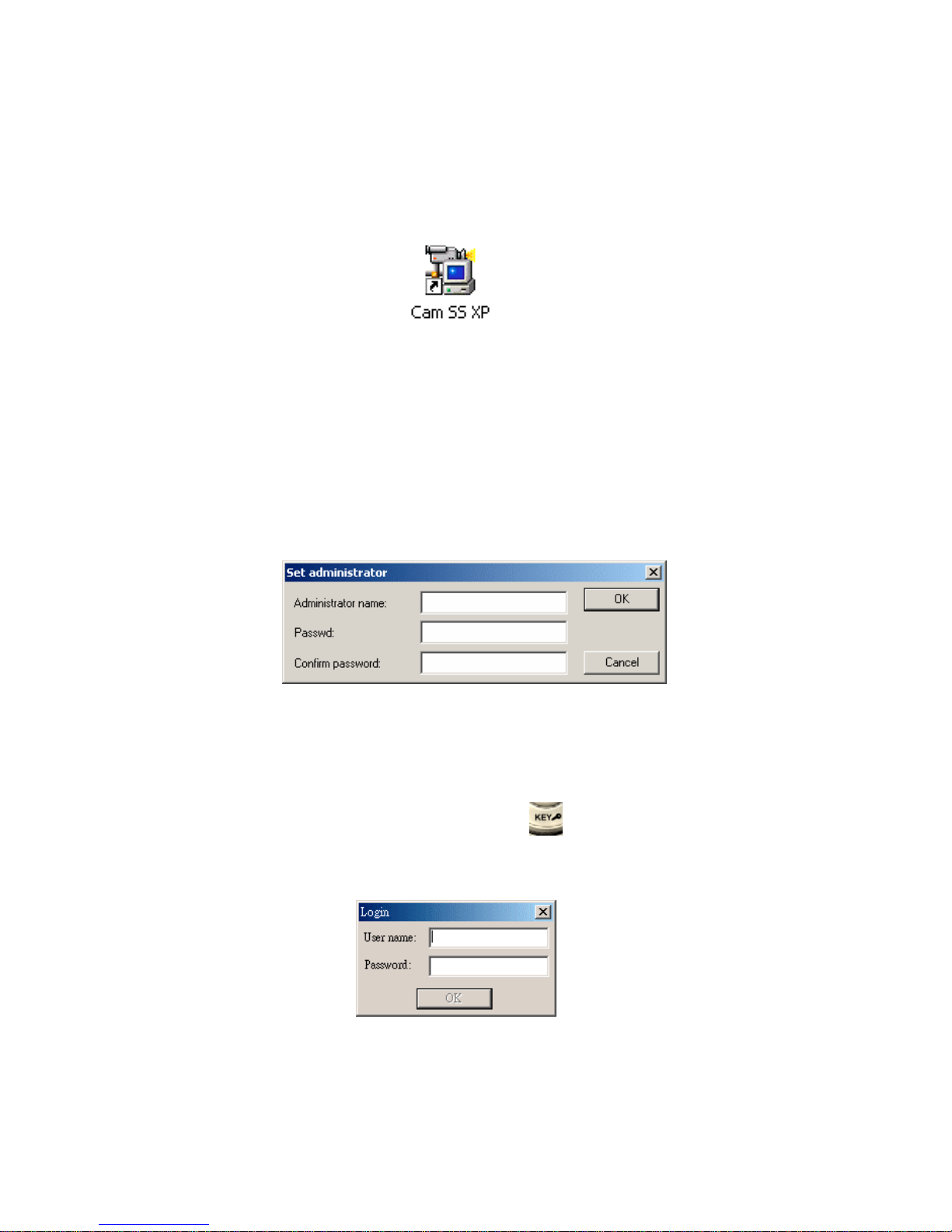
Chapter 2: System Overview
To execute Cam SS XP program, simply double-click on the shortcut icon
on the Windows Desktop as illustrated below. (It is recommended to set the
monitor resolution to 1024x768, 32bit true color or above for better screen
display.)
Alternatively, you may select the Cam SS XP program from the Program
folder.
2.1 Starting Cam SS XP
At the very first run of Cam SS XP after installation, Cam SS XP will
request user to define the user name and password for the Administrator.
The Administrator is the user with highest privileges. Please document this
appropriately. Cam SS XP system cannot be started and the System Setup
cannot be performed until the System Supervisor is set up.
From then on the Cam SS XP program will enter the main screen. Under
the main screen, press the esc. key or the login/logout button at the
bottom right hand corner, the Cam SS XP program will then request user to
login with a user name and password.
Users will have limited access for operation depending on the predefined
access auditing. These limitations do not apply to the Administrator. Please
refer to chapter 3.4 for the setting of user names/passwords and the auditing
rights associated with those users.

12
2.2 Main Screen
After entering into the Cam SS XP program, you will see the Main Screen
as follows:
The Main Screen consists of 2 sections. The top section will be the System
Image Section and the buttom will be System Function Section. To access
most of the configuration controls users need to click the reveal button, this
opens the control panel board.
2.2.1 Image Section
This section displays the images from the local cameras when the system
is not on-line with other systems. The system can be on-line with other
Cam SS XP systems through a LAN, Internet, Intranet or Modem. This
section may display the images from cameras of other Cam SS XP hosts
selected from the “Host” option in the System Function Section.
To use the PTZ control on any of the cameras on this section, move the
mouse to the desired camera view and click the left button once to select
the camera. Then, perform the desired PTZ control.
Screen Imagine: All of the images displayed in this section can be
enlarged or reduced. First, move the mouse to the desired image and
double left click on the image to enlarge it. The images will be rearranged at this time to accommodate the displays of all the images. The
image will be full screen if you double click again. Another double click
will return us to the enlarged image.

13
When the remote connection is activated, you can monitor without
recording. First we have to choose the desired remote site from the host
menu, and then choose the selected cameras for monitoring. Click the
record button , the following image will shown:
Select the needed function. Press the OK button. You will then able to
receive live video from the remote site for either recording or monitoring
without recording.
Motion Detection Area Setup: To select the motion detection area, click
and hold on the left mouse button at the image; then move the mouse to
select the desired area. Finally, release the mouse button, and the setup
then completes. There is no upper limit to the number of motion detection
areas for each camera.
2.2.2 System Functional Section
Main buttons in this system functional section are explained as follows:
Minimize: The main screen will be minimizing after pressing this
button, and will be shown in the system tray.
Full Screen: The image will be a full screen display mode when
pressing this button. Press ESC key to return to
original screen size.
On Line help: Provides on-line help for system operations.
Exit: Exits the program. (Only the Administrator may exit.)

14
About: Contains the copyrights and registration information of the
product.
Please follow the procedures below to complete the registration:
1. Click Register button using the left mouse button, the following
dialogue box appears:
2. Input the user name and registration number and then click OK button.
i. User name can be made up.
ii. You may find the registration number from the package box.
Note:The registration number is case sensitive. Please enter the
correct number. Please note the difference of the alphabetic
letter “O” and the numeric letter “0” (zero) and capital and
small letters.
There are four buttons on the right hand side of the System Function
Section; their functions are as follows:

15
Record: By pressing this button, it will activate all the preset
cameras to start video/audio recording.
Stop: By pressing this button, it will stop all video/audio
recording.
Log in/Out: During the execution of the system, the user password
is required before one can perform any of the programs
operations. If a user wants to be away for a while and
deny others’ access to the system, he/she may logout of
the program first. Then, all the programs operations
(functions) will be inaccessible. You cannot even exit
the program. The system will not be functional until a
user logs back in with his/her password. When a user
logs out of the program, it will automatically show a
full screen image. The user will then need to press the
ESC button to log back in. The login dialogue box will
appear again for the input of password and user name.
After the correct password and user names are in, the
program will then be once again functional.
Playback: By pressing this button, the playback operating panel
will appear in the lower main screen. The panel shown
as follows..
Please refer to Chapter 5 for more description of the playback panel.
Functional panel button
By pressing the button, the panel will change from
To

16
This functional panel includes Remote Access, Auto Scan, System
Setup, Log, E-Map and Mute functions.
Remote access: Allows linkage to Cam SS XP host sites.
Avaliable through modems and TCP/IP.
Please refer to Chapter 9 for a detailed
description.
Auto Scan: Enlarges the images being recorded in the
Image section and cycles through those
images in a preset order. This does not
affect the operation of recording.
System Setup: Setting of the system functions. Please
refer to Chapter 3 for the detail
descriptions.
Log: Records the times of logins and logouts for
each local user, times and messages when
alarms occur for both local and remote
sites. Please refer to Chapter 6.2 for the
detailed descriptions for the alarm log
book.
E-Map: This function not yet available.
Mute: Shuts down all the audio output from the
sound card including the alarm.
A Status Panel is located in the upper part of the function panel as
follows.
This Status Panel displays the status of the current system and the
functions as follows.
1. Host: Displays the name of the Host computer.
2. Free: Displays the hard disk spaces available in the database.
3. Current: Displays the current time.
4. Status: Display the position of the camera, video/audio recording
status. (Displays “video” for recording, monitoring mode if not

17
displayed. Displays “Audio” when recording sound. No display when
not recording)
5. Image function icon: This section includes the following functions:
Unmask Motion Detection Area:
This lets you cancel all of the motion detection areas on the
designated camera.
Snapshot:
Click on the camera wanted in the image area. The system will
capture that image and convert it into a picture, which will be
saved in the database as a BMP file. Please refer to Chapter 5.3
for detail descriptions of how to retrieve the saved picture.
Caption:
Choose the camera you want the caption to be displayed on. The
caption will display camera name, start recording time, and
current time by clicking this icon. Clicking the icon again will
hide this caption.
Caption color:
You may change the color of the caption of the selected camera
by clicking this icon; the following window then appear; select
the desired color and then click the OK button. The setting then
finishes.
Video Configuration:
This button lets you change the video configuration of a camera.
Simply drag the respective buttons to adjust the image’s
Brightness, Contrast, Saturation and Hue. To return to the

18
system default settings, click the Default Colors button.
Under the Status Panel, by clicking the left mouse button, the status panel
will be hided and shown as follows.
Display / Hide the Control Panel:
When clicking this icon, a control panel will reveal on the right hand
side of the Image Section like below.

19
The Control Panel contains 3 panels, Host, PTZ Control and
Output Control. Each panel is as follow.
Host: Selects and controls a local or a remote host
when the Cam SS XP system is online through
Modem, LAN, and Intranet or Internet. (Please
refer to Chapter 9 for further descriptions)
PTZ Control: This is primarily to control the local and the
remote PTZ cameras or speed dome cameras.
We can use this to adjust IRIS, focus, zoom,
up/down, right/left movement, cruise of preset
positions and auto pan of cameras. (Please refer
to Chapter 7 for further descriptions)
Output Port Control: This is used to control either the local or
remote output ports. (Please refer to Chapter 7
for further descriptions)

20
Chapter 3: System Setup
Select System Setup located on the function panel under the System
Function Section to setup the system as illustrated below,
The system setting contains the Board, Camera, Host, User, Database,
Sound bank, Address book, Program and I/O settings. All setting will
be described in the following chapters.

21
3.1 Board Setup
This version of Cam SS XP supports up to 4 Video Capture cards on a PC,
there are up to 4 setup areas for setting up each individual card. After the
installation of drivers and application programs is finished, Cam SS XP, at
its startup, automatically detects the quantity of Video Capture cards
installed. Boards can only be setup when the camera is not recording. This
information can be viewed in the following screen.
Note: Setup should be set under not recording situations for the system
to be saved and valid.
- Frame Size
This is used to specify the frame size for image displaying, processing
and storing.
Frame size for NTSC system: 640x480: 640 pixels by 480 pixels.
Frame size for PAL system: 704x576: 704 pixels by 576 pixels.
- Name
The default value is the corresponding Video Capture card number,
ranging from 1 to 4. You may choose a name easy to identify for
purpose of better managing the entire security network.
- Recording Speed
This is used to specify the recording speed, either in fps (frame per
second) or spf (second per frame) (Clicking this button will toggle

22
between fps and spf). Cam SS XP automatically adjust the recording
speed down to the maximum speed of the CPU, if the specified speed
exceeds the PCs maximum speed for image processing. (The default
value is 30 fps in NTSC system and 25fps in PAL system)
- Full speed recording when alarm
If the user enables this function, it will be set to go to full speed
recording when an alarm is triggered. This function is used to allow the
camera to be set to a lower speed for normal recording. When alarm is
triggered, the camera recording will then automatically speedup to its
maximum speed.
- Exit
Click OK button to finish board setup.
3.2 Camera Setup
Selected the Camera and the following will show:
There are Camera Enable, Camera Name Setup, Recording Enable,
Display Image, Audio Recording Enable, Check Video Lost, PTZ
Control Setup, Image Setting, Alarm Enable and Alarm Setting. Please
refer to Chapter 4.2 for more detail.

23
3.3 Host Setup
The following will appear when Host is selected.
Automatically launch Cam SS XP
Allows you to set to automatically launch the Cam SS XP application
upon PC start-up.
Automatically Record
Allows you to set to start recording upon Cam SS XP start-up.
Automatically connect to server
Allow you to set to automatically connect to the Cam SS Server upon
its start-up. The system will automatically connect it to the same Cam
SS Server it connected to previously.
Automatically power off the system
If this function enabled, when the Administrator closes the Cam SS
XP program, it will also shut down the computer. If this function is
disabled it will close Cam SS XP program only.

24
Automatically reset the system
If this function enabled the Cam SS XP program will automatically
reset the computer on a scheduled basis. When setting up this function a
user can click Setup to set the time interval for auto reset. A user can
only choose one of the following three schedules for setup:
- Every Day: Users can set to reset the system once every day.
- Every Week: User can set to reset the system once every week. It is
then set to reset at the specified time and day once
every week.
- Every Month:User can set to reset the system once every month. It
is then set to reset at the specified time and date once
every month.
Note:
1. This function is primarily used to cope with possible lockups
resulting from long periods of up time. Resetting the system on
a scheduled basis will reduce this possiblity.
2. If this function is enabled, the system will enable three functions
automatically: Auto Launch of Cam SS XP, Auto-Connect to
Cam SS Server and Auto-Start Recording. This is done so the
system can return to the original recording mode and
automatically connect to the server after it is reset.
3. Under the normal Windows network system, you will be asked
to enter a password when starting the computer. When setting
Auto functions for Cam SS XP, you will need to cancel the
password setting (Please refer to Window2000 user manual for
disabling this password setting).
■ Optional warning sound.
- Host lost: When any linked host is disconnected the local host will
produce an alarm sound to alert the operator that some other host has
been disconnected. The alarm log will record the name and time of
the disconnected host.

25
- Local login fail: When the system is working, it will trigger an alarm
and play the designated sound file if an incorrect login name or
password is entered.
- Remote login fail: If a remote user links to this system and is an
unauthorized user, or his name/password is incorrect, the system will
trigger an alarm and play the designated sound file to alert the local
system operator in order to prevent any wrongful intrusion to the
host.
■ Select sound:
Click Select sound, users can select a sound file from the programmed
Alarm Sound Bank to serve as the common alarm sound when any of
the foregoing three events occurs.
■ Modem dial timeout
The Modem will stop dialing when the remote access is not able to
connect in the time period that the user sets. The default time will be set
at 120seconds.
■ Modem answer timeout
If the modems were connected, the modem did not receive any signal
from the other modem in the time period that the user sets. (The default
is 120 seconds.) The modems will disconnect automatically. You will
then need to reconnect for remote access. The default time will be set at
120seconds.
■ File length (Video File Length)
The recording time for the video file is from 10 ~ 120 minutes. The
default value is 60 minutes. (Note that this is the length of recording
time rather than the size of the file.) It is recommended that the
parameter shall not be set too short; or the searching time may be long
due to too a multitude of video files. There is also a limit on the number
of files in each directory of the hard disk.
■ Auto Scan
The Cam SS XP system will automatically enlarge all the camera
images one at a time and dwell on each camera for a predefined period
of seconds (default is 30). Click the button to stop Auto scan.

26
3.4 Users
The following will show when clicking this button.
At the very first run of Cam SS XP, it is required to key in a password to
the System Administrator (the user with the highest access auditing). The
very first user that appears (in a red head) in the display is the System
Administrator. If one desires to set a new user, click the New button..

27
3.4.1 New User Setup
Simply press the New button to enter the setup screen for a new user.
Note: Only the System Administrator can add, delete or edit a user
profile.
■ The setting for “User Info” is as follows:
1. User Name: type a new user name into the box
2. Password: type the password into the box
3. Confirm: type the password again for reconfirmation
■ Auditing is used to set up the user’s access auditing as described
below. You may grant one or more of the following access auditing by
checking the boxes ? in front of them. The access auditing is set as
follows:
1. Start/Stop: Enables a user to Start Recording and Stop
Recording.
2. System: Enables a user to access System Setup, Unmask
Motion Detection Areas and use the Video
Configuration functions.

28
3. File: Enables a user to access Playback, Log, Snap shot
and caption functions.
4. I/O: Enables a user to access Output Device.
5. PTZ: Enables a user to access PTZ control and use
Dome Camera control functions.
6. E-map: Enables a user to access E-map functions.
7. Remote Access: Enables a user to connect to other Cam SS XP
workstations remotely.
8. Camera selection: Enables a user access to the images from the
authorized camera. The cameras without
authorization will not be shown.
After all settings are finished click OK to complete configuration.
When the specified user logs in with this user name and password next
time, he/she can have only access to the granted functions.
Note: In the Cam SS XP system, users will not need to be
separated into local users or remote users. Authorizations
for the same login name and password will be the same.
3.4.2 Editing Users
To alter user’s password or access authority, select the user’s name and
press Edit. The following will be displayed for editing user setup.
Note: A common user can only alter their own password but not the
access authority.

29
3.4.3 Delete Users
Select the user to be deleted and click the Delete button to delete the user.
(Only the Administrator can delete a user)
3.5 Database Setup
This option is used to specify the directory and hard disk in which video
files are stored. The screen will be as follows:
3.5.1 Adding A New Database
Select the New button to add a new database, it then goes to the screen as
follows:
- First, give it a name, then click … to set up hard drive and directory.

30
- Select the desired drive and directory, and then click OK to finish the
setup.
- The default-reserved space on a single hard disk drive is 1000MB.
- You may choose to recycle a hard disk; however, you need to cancel the
Recycle option if a recorded image is to be kept.
- There is a function for disk full alarm. If user enables this function and
selects a warning sound by pressing … from the alarm sound bank,
when the hard disk is full, the system will play the selected warning
sound.
- Click OK to finish the setup.
Note: Setup can be performed only once for each hard disk drive.
Duplicate databases are not allowed.
3.5.2 Editing a Database Entry
To edit a database entry in the list, select the desired entry and click the
Edit button. The way of modification is the same as that of adding a new
database.
3.5.3 Deleting a Database Entry
To delete a database entry from the list, click on the desired entry and then
click the Delete button. A request for confirmation prompts, click OK, the
database entry is then deleted. (Only the system administrator can delete
databases)

31
3.6 Sound Bank
Select Sound bank, the following screen will be shown.
3.6.1 New Sound
To add a new sound file, click New Sound and the following dialogue box
will appear.
First, give a name to the sound file, and then click Select to choose a
sound file.

32
After a sound file is selected, it returns to the following screen.
Click Preview to ensure the selected file is correct.
Then Click OK to complete the setup.
3.6.2 Edit
To edit a sound file, simply select that file entry and click the Edit button.
3.6.3 Delete
To delete a sound file, simply select that file entry and click the Delete
button. (Only the system administrator can delete sound file)
3.6.4 Preview
To preview a sound file, simply select that file entry and click the Preview
button.
Notes:
1. The field, Voice Modem with two valid values Yes and No, shows
whether the sound file can be transmitted to a telephone through a
modem.
2. The file to be transmitted through that modem to a telephone must
be in the format of PCM 8000Hz, 16-bit, mono.

33
3.7 Address Book
The Address Book can store remote telephone numbers or IP address that
are frequently used to facilitate the remote access and remote alarms.
3.7.1 Adding a New Entry to the Address Book
To add a new entry to the address book, click the Add button, the
following dialogue box appears.

34
- Adding A New Server:
This is primarily used to connect to a remote server. First, give that
name of that server; next, choose Server from Type field; and then,
type the IP address into the field, Phone No./IP address. Finally, click
OK button to finish the setup.
- Adding a Remote IP:
The address book is used to transmit an alarm message to the remote
Cam SS XP system via LAN or Internet. First, input the “Host” name
of the remote Cam SS XP system (please note that the “Host” name is
case sensitive); next, select Remote IP on Type pull-down list. Last,
click OK to finish the setup.
- Adding A Modem:
This is used for modem communication including remote access and
remote alarm. First, input the name of the modem; second, select
Modem on Type pull-down list; third, input the remote Cam SS XP
System’s phone number. Click OK to finish the setup.
After the setup is finished, it comes to the screen as follows:

35
3.7.2 Edit
To edit an entry in the address book, click on the desired entry and then
click the Edit button, or simply double click on the entry that you wish to
edit.
3.7.3 Delete
To delete an entry from the address book, click on the desired entry and
then click the Delete button. The entry is then deleted.
3.8 Program Setup (Scheduled Recording)
Clicking on the program tab will bring up the following window:

36
3.8.1 New Recording Schedule
Click Add and the following window will appear:
1. Please enter start date/time and end date/time into the “From” and
“To” fields respectively. When inputting the date/time, you may type
them directly into the fields, or use the mouse to click the up/down
arrows to the right of the fields.

37
2. “Repeat Mode”: You may choose the frequency in which to repeat the
schedule, “Once only”, “Once a day (Everyday)”, “Once a week
(Every week)” or “Once a month (Every month).”
- Once Only (Only Once):
Please input the starting and ending date/time.
- Once a day (Every Day):
The date fields are disabled because this option executes on a daily
basis. Please input the start and end time.
- Once a week (Every Week):
It is required to input the starting and ending days of the week /time.
The “date” field automatically changes to “Day of the Week” when
this option is clicked.
- Once a month (Every Month):
It is required to input the starting and ending days of the day /time.
The “date” field shows the day only but no year and month.
Note: If the desired schedule time crosses 12:00 is recommended
to split the schedule into two,
E.g. Split PM6:00:00~AM9:00:00 into
PM6:00:00~PM11: 59:59
and AM12:00:00~AM9:00:00.
3. Recording Mode:
- Recording: Normal recording mode.
- Audio Recording:
In case of a schedule conflict, the first programmed schedule is used,
i.e. other scheduled recordings and audio recordings are all
cancelled. Please refer to “Audio Recording” in the subsequent part
of this chapter.
- Snapshot:
This function allows us to takes a snapshots at a predetermined time
interval. Cam SS XP then saves the image files into a default folder
named in the following format: “pan+00hhmmss”. (“a” stands for
the pictures taken under alarm situation, n is the number of picture
taken under the alarm situation. Without “an” means the picture was
taken in normal time. “a0” stands for the first picture taken.)
You may open snapshot files through the Explore window button.
4. Camera selection:
This is used to select the required cameras for the above scheduled

38
recording.
5. When all of the schedules are set, click the OK to add it to the
schedule list.
3.8.2 Edit Program
Click on the desired program for editing. The follow screen will then be
shown:
Select the items to be altered, click ok to finish editing and save the
alterations and return to the main screen.
3.8.3 Deleting a recording schedule
Simply click on the desired schedule entry and then click the Delete
button to delete that schedule
3.9 I/O Devices
Please refer to Chapter 7 for a detailed description of I/O Device settings.

39
3.10 E-map
3.10.1 E-map Setup
After entering the System Setup menu, the following box will
appear under the E-map tab.
-New: Press the New button to create a new map.
Please press the select button to browse for the map file. Then
input a name for that map for easy identification. (e.g. Floor 1,
Court Yard…etc.,) The map file being used must be in .BMP
format, and preferably with a resolution of 640x480. Click OK
after selection is done, it then comes to the E-map screen as
follows:

40
To set up the E-map, move the mouse to the original e-map
name. Press the new button to add a second level e-map. The
following screen will then appear.

41
The following will appear when the setting of the tree-form emap is finished.
To add a camera click the button located in the left upper
corner; the cursor then turns to “+”. Move the cursor to the
desired position and then left click to finish the camera location
setup.
As illustrated above, the red arrow points to the newly added
camera.

42
Double click on the camera icon to assign a specific camera to
the desired Host name, camera, and board number. This allows
us to connect the E-map with the actual video images.
Selecting the button in the left upper corner to add a level
button on the map. The cursor then turns to “+”, Move the
cursor to the desired position and then click the left mouse
button to finish the level button location setup.
Double clicking the level button will then allow you to link a
second e-map to that button. This function allows us to
combine multiple e-maps to better accommodate a multi level emap structure.

43
-Edit: To edit a camera entry in the list, click on the desired
entry and then click the Edit button. You may then proceed to
edit the location or ID of the camera on the e-map.
-Delete: To delete a camera entry from the list, click on the
desired entry and then click the Delete button.
-Close: Click Close to exit the E-map Setup function.
3.8.2 E-map Operations
Selecting the E-map function under the System Operation Section
will produce the following screen.

44
As illustrated above, if a camera is shown as , it indicates
that the camera is recording; if it is shown as , it indicates
that the camera is idle. If it is shown as , it indicates that
there might be a faulty setting for host name, Board ID, or
camera ID. If this happens during the remote monitoring mode,
it indicates that the host name was not the same as the remote
Cam SS XP system, or not yet connected with the Cam SS XP
system.
As shown below, this tree form graph is used to select the emaps for different levels when there are 2 or more e-maps
Double click the desire camera on the e-map to enter the
recording screen. This shows the corresponding image and
camera.
If a camera is shown as , it indicates that the camera is
recording; if it is shown as , it indicates that the camera is

45
idle. Other cameras will be shown as (Recording) or
(Idle). From the above operation, it is very easy to access
to the camera screen and location.
Click the right mouse button to access to the setup content.
Click the right mouse button on the level button to access to the
setup content for level button.
3.10.3 E-map and Alarm
In addition to the preset alarm functions (Refer to Chapter 6 for
detailed descriptions), as a recording camera activates alarm
function and an alarm is triggered, click button and it
will come to the following screen:
As illustrated above, icon denotes a camera triggering an
alarm. Thus, it is easy to locate the alarming camera on the emap and be taken care speedily.

46
Chapter 4: Recording
After a user had finished camera setup, the recording can be activated.
When clicking the recording button, system will activate video and audio
recording preset by the user as follow.
4.1 Recording Windows
4.1.1 Activate Recording of Cameras
You may open all of the windows and start recording of all cameras by
clicking the button. (See above)
4.1.2 Inactivate Recording of Cameras
You may close all the windows and stop recording of all cameras by
clicking the button.
4.1.3 Camera Status Display
The above screens indicate when the camera in not recording yet and is
still idle; when the camera is working, but the view is not displayed
(recording still normally working); and when the camera is not connected.
Note: Cam SS XP’s version does not support for each camera to
activate and inactivate recording individually. All cameras
need to be activated and inactivate at the same time.

47
4.1.4 Caption
You may display the name of the camera view by clicking button (as
illustrated in the upper left corner of the diagram below). The caption
contains board name and camera name.
You may cancel the caption display by clicking button again.
4.1.5 Caption color
You may change the color of the caption of the selected camera by
clicking button; the following window then appears; select the desired
color and then click the OK button. The setting then finishes.

48
4.1.6 Unmask Motion Detection Area
By pressing the button in the status panel you can cancel all of the
motion detection areas of the designated camera.
4.1.7 Snapshot
This button lets you capture still images during recording. (This function
works only when cameras are turned on.) The images are stored in BMP
format. You may edit or process these images using common image
processing software, print them out, or email them to people. Please refer
to Chapter 5.3 or more detail and loading pictures.
4.1.8
Video Configuration
This button lets you change the video configuration of a camera. Simply
drag the respective buttons to adjust the image’s brightness, contrast,
saturation and hue. To return to the system default settings, click the
Default Colors button.
4.2 Recording Setup
This button allows us to preset the recording functions of a camera before
that camera is activated. Please refer to the following for more details.
4.2.1 Camera Setup
You need to preset the camera function before you activate recording as
shown below.

49
Every camera has the same optional settings. Each seting is detailed as
follow..
■ Camera function setup
- Enable (Enable Camera)
This function is used to allow the activation of cameras. If this box
is checked the camera will then be disabled and not recognized by
the system.
- Record (Enable recording)
Select this function to activate camera recording. If not chosen, the
camera will be under monitoring mode (only displays images, does
recording).
- Display (Display image)
The image will only be displayed when this function is selected. If
not selected, the image will not be shown. If the recording function
is activated, it will not be affected. (It will display as “working”)
- Audio (Enable Audio recording)
When this function is selected the recording of the audio will be
activated. (Only the 1st and 2nd camera from each card can use the
onboard audio recording )

50
- Video Lost (Check video lost)
Every camera has its independent check function for lost video.
When this option is selected, whenever the camera loses the video it
will display as video lost and may trigger the alarm function.
Noted: The enable alarm option must be selected and setup for
this function to be activated.
- Alarm (Enable Alarm)
Select this function to enable the alarm. After this is enabled the
alarm setup can be done by pressing the setup button on the right
hand side. (After the alarm function is enabled you will need finish
the setup procedure along with the Motion Detection setup.)
■ Camera Name Setup
A user can change the camera name for easier access and search.
When an alarm is triggered, the area can then be found promptly.
■ PTZ control select
When a PTZ camera or speed dome camera is connected, you will be
able to control up, down, left, right, and zoom functions of that camera.
■ Image setting
An image setting includes the following.
- Image Quality
This function allows you to be able to adjust the image quality. By
dragging the slider bar you can adjust the image quality from high to
low. A higher image quality means a lower compression ratio (i.e. a
larger amount of data); by contras a low image quality means high a
compression ratio (i.e. a smaller amount of data).
- Sensitivity
This function allow you to adjust the sensitivity of alarm triggering
depending on different operating environments, e.g. the quality of
camera, distance, lightness, background lightness and object size
Note: High sensitivity may cause false alarms as well as increases
the amount of data generated by recording. In adjusting the
sensitivity, it is recommended to take the camera quality
and the surrounding environment into account to avoid
false alarms.
- Number of the changed picture
Alarm will be triggered only if the number of variations occurred in

51
sequence greater than the default limit. You may adjust this limit to
avoid false alarms.
4.2.2 Mode
Camera mode setup works in four modes.
1. The camera is both in “recording” mode and “monitoring” mode (It
displays camera views while recording).
2. The camera is in “monitoring” mode but not in “recording” mode (It
displays camera views). Close the recording option and open the
display view option.
3. The camera is in “recording” mode but not in “monitoring” mode. (It
displays “WORKING” view.) Open the recording option and close
the display view option.
4. The camera is neither in recording or monitoring mode. (It displays
“IDLE” ) Close the recording and the display options.
When the “Recording” mode is turned on, the System Status panel is
shown as VIDEO. When the recording mode is turned off, the System
Status panel will not been shown.
Audio recording will be activated simultaneously when the indicated
camera starts recording if the “Enable audio” mode is turned on.
System Status panel is then shown as AUDIO. When the mode is
turned off, the System Status panel will not been shown.
4.2.3 Motion Detection Setup
During recording, if you select a motion detection area (by clicking on a
point, holding the left button of the mouse, dragging it to the desired point,
and then releasing the button.), the system then undertakes motion
detection against the selected area. There is no limit to the number of

52
motion detection areas.
The mask area in the diagram below is the motion detection area. The
green color frame means that no alarm is triggered.
The detection area is shown in red color, this means that an alarm has been
triggered. (The enable alarm option under Camera Setup must be enabled
before alarm triggering can function when using the motion detection
option.)
The detection area in the diagram below is shown in blue color, this means
that the alarm has been triggered but the enable alarm option has not yet
been configured for that specific camera.)

53
4.2.4 PTZ control select
This option allows you to select a PTZ control device. Clicking the Select
button will bring you to the PTZ control setup window. (Provided that the
name, type, and address under the I/O Device window have already been
set up in advance.) Then simply select the desired PTZ control device.
4.2.5 Alarm setup
By clicking the Enable Alarm button and then the Setup button under the
Alarm Setup frame, the following Alarm Setup window for Cam SS XP
prompts. (Please refer to Chapter 6 for a detailed description of setting up
alarms.).
4.3 Preview
During regular recording if a user needs to preview an image from a certain
time, simply select the desire camera under the recording window. Click
the right button of the mouse, and select Preview. The following will
show:
Input the time in minutes previous to the current for which you wish to
preview. (Time range for preview is 1~99 minutes.)

54
Chapter 5: Playback
The following description will show you how to find and load saved video
files, and load saved pictures.
5.1 Video Playback
Click the play button. You may then search for the, it then comes to
the screen as follows:
Before this function is activated, you will need to input the Host ID and any
other desired search options.
5.1.1 Parameter Mode
1. Search By Host name:
Searching of the host name includes the host name of the local
computer and any of the connected remote hosts. All names will be
shown by scrolling down the list to the right of the host name as
follows.
2. Search By Date:
To search for video files by date (including year, month, and day).
3. Search By Time:
To search for video files by the start/end date and time (including year,
month, day, hour, minute, and seconds).
4. Search by Camera:
Only the cameras which had saved video files can be selected. If the
specified camera has no files associated with it, then it can’t be
selected.
Note: Maximum of 4 cameras can be chosen at a time. You need
to finish playing the chosen files to be able to select another
4 cameras. You do not need to exit the played file to have
more than 4 cameras playing at the same time.
After selecting the searching parameters, click the Play button to play.

55
4 playback images can be played simutaneously.
5.1.2 File Mode
Clicking the File Mode button on the Playback Panel will bring up
the following window.
The screen will be divided into left and right sections. The left displays
the saved video files. The right displays the saved video images. It

56
contains 2 kinds of video files, continuously and snapshot images. Both
kinds of video can be played using this playback function.
- Host: The top level is the host name. Exclude the host name of the
local computer you are working on, it also includes any of the
connected host names. A user will not be able to see the connected
host name if access to playback is not allowed.
- Database: The second level is the database. The name and the file
names are set under the database setup.
- Date: The third level is the date directory. Cam SS XP saves the
video files to a new date directory everyday. It does this for easier
search, and to give the end user the ability to delete entire days of
video easily.
- Host name: The fourth level again uses the name of the host. This
host name is the host where the saved files are from. A local host
name means that a local host saves the files. If the host name is not a
local host name, it means that the files were saved from other Cam SS
XP host.
- File: The fifth level consists of three archive names, Video, Picture
and Clip. Video files are saved under the Video Files. Snapshots are
saved under Picture, and the video cut is saved under Clip.
When you find the desired file from the left side of the screen double
click on it or right click and select open to playback the selected video
file.
■ Open file:
In the file mode, 4 images can be played simultaneously by using the
right button and the shift key to highlight up to four video files.
■ Download:
Select the file from another host’s database; by clicking the
Download button, you will then be able to transmit the file to a
database located on your local computer.
■ Export an image file:

57
Selected the file need to be exported. Then click the right button of
the mouse and chose the Export function. The following screen will
be shown. Select the files then press Enter to export the files to the
specified file path.
■ Delete (Deleting A Video File):
Simply select the video file(s) using the mousse then press the Delete
button to delete the selected video file(s). The delete function will
only work when the system administrator is logged in.
5.2 Video File Playback
By double clicking on the desired file you can playback the video file as
illustrated in the following window.
The playback window consists of three parts, including
- Message area
- Control Panel
- The Video View
Message Area:
It includes the relevant information such as host name, operating state and
the playback speed.

58
- Host name and time
- Operating Status: the operating status of the window, i.e. “Playing” or
“Pause”.
The Video View:
It includes the information such as time, Video Capture card names and
camera names.
- It displays the start date/time of the file.
- It displays the ended date/time of the file.
- It displays the current date/time.
Playback Control Panel:
The playback control panel consists of 2 parts. The above picture shows the
basic functions of the control panel. And when pressing the button
an extended control panel will be shown as below. Press the button again to
hide the extended control panel.
Each playback function button is described as follows.
5.2.1 Stop
This is used to stop the current playback, not the playback window.
5.2.2 Play
This button functions the same as Play button of traditional video player.
When clicking this button during fast or slow playback, the playback speed
returns to normal.

59
5.2.3 Pause
This button functions the same as the Pause button of the traditional video
player. Clicking this button during playback pauses the video. To continue
the playback click this button again or click the play button.
5.2.4 Backward Search
This button functions the same as the Rewind button of the traditional
video player. Click this button, and the video will move 160 frames
backwards.
5.2.5 Forward Search
This button functions the same as the Forward button of traditional video
player. Click this button and the video moves 160 frames forward.
5.2.6 Forward a single frame
When this button is clicked, the video will moves forward a single frame at
a time. The image will remain paused until the play button is clicked.
The playback speed will then return to normal.
5.2.7 Backwards a single frame
When this button is clicked, the video will moves backwards a single
frame each time. The image will be paused until the play button is
clicked. The playback speed will then return to normal.
5.2.8 Snapshot
By clicking this button, you may capture still images during video
playback. The captured image is stored in BMP format. You may edit or
process it by using any common image processing software, print it, or
email it. (File names for snapshots form automatically, you do not need to
set one.)
5.2.9 Start Video Clip
Click this button during video playback to start a video clip. The record
time will then become the start of the video cut.

60
5.2.10 End Video Clip
Click this button during video playback, and the video cutting will end.
This will then become the end of the video clip.
5.2.11 Save the Video Clip
Click on this button, and it will be saved under the Clip folder under the
current date.
5.2.12
Playback clip
After video is cut you may play it back by clicking this button.
5.2.13 Caption
Click the icon, the playback window shows the name of the Video
Capture card, name of the camera, the starting time, and current time of
the specified camera.
5.2.14 Caption Color
Click the icon; the user can change the color of the caption.
5.2.15 Zoom In
You may click this button to enlarge an image from its current size. Each
click will enlarge the size by 25%; up to 200%.
5.2.16 Zoom Out
You may click this button to reduce an image from its current size by 25%;
you may reduce an image down to its original size (100%.)
5.2.17 End
Clicking this button will stop the playback function and close the playback
window.

61
5.2.18 Fast and slow playback
Above is the control panel for playback speed. The middle is playing at
the speed of 1x. Clicking each point to the right increases the speed in the
following increments: x2, x4, x6 and x8. Clicking each point to the left
will reduce the playback speed in the following increments: 1/2,1/4,1/6,
and 1/8.
5.2.19 Playback Time Scroll Bar:
This displays the relative time position of the current display in the video
file. You may speed up the playback by dragging the time pointer using the
mouse or the function buttons, .
5.3 Load picture / Print picture
Select the picture file under file mode. Double click on the chosen picture to
load that picture. You can preview theses pictures when recording or during
playback.
- Zoom In: Click this button to enlarge the picture.
- Zoom Out: Click this button to reduce the picture.
- Print: Click this button to print out the chosen picture. (Printer
driver setup is necessary before using this function)

62
Chapter 6: Alarms
Cam SS XP system’s alarm functions are categorized into three types as
follows:
1. Triggered by image alteration in motion detection area.
2. Triggered by “Video lost”.
3. Triggered by (sensor) signal from the input port (please refer to
Chapter 7 IO Device.)
6.1 Alarm Setup
Each camera has its own independent alarm setting. You can find the
related activation options and setting buttons in Camera Setup dialogue
window under the Camera Setup Section.
You need to check enable alarm in the alarm setup before you can setup the
alarm. First click the Setup button to enter the alarm setup window.

63
6.1.1 Alarm Event Period
This is used to set the length of time that an alarm will last. No new alarm
will be triggered during this duration. The default value is 180 seconds.
The minimum is 10 seconds. It is recommended that you set this value for
more than 60 seconds.
6.1.2 Activate condition
You may activate alarm functions by a predefined schedule table. After
you select Activate by schedule table, click the Schedule button, the
following Schedule window displays.

64
1. Adding a new alarm schedule
Click the New button to add a new schedule. There are four repeat
modes for an alarm schedule: Only Once, Every day, Every Week
and every month. First, select the desired repeat mode. Then, input
start/end day (week) and time into the boxes to the right of the “From”
and “To” fields. You may input the data directly or click the arrows to
the right of the fields, click the OK button to add a schedule to the list.
Note: If the time to be set crosses 12:00, it is recommended to split
the schedule into two, e.g. Split PM6:00:00~AM9:00:00 into
“PM6:00:00~PM11:59:59” and“AM12:00:00~AM9:00:00”.
2. Editing the schedule
Click the desired schedule and click the Edit button to edit the
schedule.
3. Deleting a schedule
Click the desired schedule and click the Delete button to delete a
schedule. (The delete function will only be accessible when logged in
as the system administrator.)
4. Closing the schedule window
Click Close button or to exit the window.
6.1.3 Alarm Actions
There are two types of alarm actions, i.e. local and remote alarm actions.
Listed below are four items:

65
- Playing warning sound…….…Local alarm
- Snapshot……………………...Local alarm
- Activating the output port.……Local alarm.
- Remote alarm………………..Remote alarm.
1. Playing Warning Sound
When this option is activated and an alarm occurs, the Cam SS XP
system plays the designated sound file. A sound file must be specified
(Cannot be a blank field) to play the alarm sound when an alarm
occurs. Click the Select button, the Sound bank screen appears as
follows:
Click on the desired sound file and click the OK button. The sound
name will appear in the field of “playing alarm sound”. For the alarm
sound bank setup, please refer to the Alarm Sound Bank Setup in
Chapter 3.6.
2. Take pictures (Snapshot)
When this option is activated and an alarm is triggered, the Cam SS
XP system immediately captures the images (in BMP format), which

66
will be stored under the file of the capture date. You may use then
Load Picture or print the pictures for review purposes.
Number of Snapshots this is used to set the number of snapshots.
Note: Please note that activation of this option may consume
large amounts of hard disk space.
3. Enable output port (Output Alarm)
When an alarm is triggered, it can activate the output port of a local
Cam SS XP system to send signals to other external devices, e.g.
alarm bell. (Please refer to Chapter 7 I/O devices for I/O devices).
4. Remote Alarms
This option must be activated so that the Cam SS XP system can
perform the remote alarm functions when an alarm occurs. You first
need to setup the remote alarm actions. Each time when an alarm

67
occurs, the Cam SS XP system will then execute these actions in
sequence (in the sequence that they are listed on the list). Click the
Setup button, the Remote Alarm Setup screen will appear:
Adding a new alarm action
Click the right button of the mouse and select New to enter the New
Remote Alarm window.
A. Remote Type
By clicking the arrow to the right, you can see three remote types.
Select the one as desired.

68
- Telephone: it can dial out a number of a normal phone or mobile
phone upon alarm.
Action options available: phone speech.
- Pager: it can dial out to several numbers of pagers upon
triggered alarm.
Action options available: paging messages.
- Computer: It can notify a number of remote Cam SS XP
systems; if a modem is used to dial out, it can dial once only and
all the phone and pager schedules must be cancelled.
Action options available: Live video.
Next, click … to open the Address Book as follows:
Only the corresponding type of remote device(s) will be
displayed. Select the desired remote device.
B. Select the action options available:
- Telephone sound

69
Click … button to open the alarm sound bank, then select the
desired sound.
Redial time: To setup the redial times if not connected. The
waiting time will be the time setup in the host computer’s
modem dial timeout function.
- Paging Messages
Send a paging message to a remote pager
- Live video
During the alarm duration you have the option to send live video
to the designated remote Cam SS XP System.
C. Click OK
button to set up the remote alarm action.
The finished remote alarm settings are illustrated below.
Note: The duration of local alarm shall match the time required
by the remote alarm actions. The recommended value
should be a minimum of 60 seconds.
Remote Alarm Actions Setup
There are three items:
1. Remote Type: it displays the type of the remote device.
2. Name: it displays the name of the remote device.

70
3. Action: the set actions.
Telephone= Telephone speech. Inside the () is the playback
message file name and the times of redial.
Paging= Paging Message.Inside the () is the playback message
code number.
Recording = Transmitting live video images to Cam SS XP’s
remote sites for recording.
Editing the remote alarm setup
Select the setting to be edited, and the EDIT
button to edit the alarm
settings.
Deleting the remote alarm setup
Select the setting to be deleted, and click the Delete button to delete a
schedule. (The delete function will only work when the system
administrator is logged on.)
Exiting the remote alarm setup window
Click the Close button or to exit this setup window.
When this alarm is triggered by a local or remote Cam SS XP
system, the Host icon will be changed. Click the Host tab under the
System function section; the icon will then return too normal.
6.2 Alarm Log
You may find the Log button under the function panel in the System
Function section.

71
When the local Cam SS XP System’s alarm is triggered or an alarm is
received from the remote end, these alarms will be saved to the alarm log in
the order of occurrence. The log sheet will display the alarm time, the name
of the host that triggers the alarm, board name, camera name, alarm type
(i.e. local or remote), the way the alarm is triggered, i.e. by intrusion into
the motion detection area, by video lost, or by the signal received from the
input port.
The confirmation section in the alarm log indicates when the alarm video
has been played; the confirmation section will change from “No” to “Yes”.
This means that the alarm log has been checked.
Click the Open button to play the alarm video of the selected alarm log
entry; or directly double click on the desired alarm log entry to play its
recorded alarm video. If no video file exists, then nothing will happen.
Click Delete all to delete all of the alarm log entries.
Click the Print button to print out the alarm log.

72
Chapter 7: I/O Device
The Cam SS XP system can control an external I/O (Input/Output) device.
I/O devices can be generally divided into these three categories as follows:
1. RS232-to-RS485 interface I/O control device. It controls an external
I/O device.
2. RS232-to-RS485 interface (high speed) dome camera control.
3. VGIO on Video Capture Card controls input/output device.
Thus, its operation is divided into two parts, i.e. I/O Control and Camera
PTZ control.
7.1 I/O Device Setup
You may find the I/O Device Setup button on the function panel in the
System function section. Click the button and enter into the I/O Device
Setup screen:
7.1.1 Selecting the desired I/O device
RS232/RS485 interface: (Allowing the connection of 32 external I/O
modules within a distance of 1.2 kilometers. Dependent on the loading
situation, the connecting distance and numbers will be vary)
PT811 I/O device: (8 ON/OFF inputs, 8 digital output modules)
Address range: 0x01-0xFF. PT811’s address shall be set before the

73
delivery of goods is made; or else you shall seek the manufacturer for the
required hardware and software support.
Each PT-811’s address must be different from that of any other PT-811 on
the same COM port to avoid error in control.
Dome Camera
This system can simultaneously control up to 16 dome cameras. Since a
control command is sent out by signals via the RS-485 interface to all
cameras, a camera shall adjust its address in order to identify whether it
can receive the command. Therefore, you must remember a camera’s
address and its setup location so as to make the correct setting and avoid
any error in control.
Since there are many brands of cameras and each brand has different
internal control command, this system will continue to provide additional
brands for users’ choices.
1. DynaColor CA720 dome camera
The valid address range is 0x1-0xDF(in hexadecimal address). For the
address setting, please refer to the operating guide of CA720.
2. Lilin PIH717X dome camera
The valid address range is 0x1-0x40(in hexadecimal address). For the
address setting, please refer to the operating guide of PIX 717.
3. Pelco-D dome camera (Support D)
The valid address range is 0x1-0x80(in hexadecimal address). For the
address setting, please refer to the Pelco’s operating guide..
4. Mikami PTC103A dome camera
The valid address range is 0x1-0x40(in hexadecimal address). For the
address setting, please refer to the operating guide of PTC103A.
5. Sensormatic dome camera (RS422 Interface)
The valid address range is 0x1-0x63(in hexadecimal address). For the
address setting, please refer to the operating guide of Sensormatic.
The control code of each manufacturer is different and incompatible to
those of others. Do not mix/use different vendors’ devices on the same
COM port. The address of each device on the same COM port must be
unique. Please input the address in hexadecimal format to avoid any
control error.
Watchdog Function of Video Capture Card

74
Each Video Capture card has a watchdog function. Users can choose VG
IO card among the Device Types in IO Device Setup, and enter into the
Device Setup to activate the watchdog function. However, the reset signal
of the PC main board must be connected to the JP2 (1,2) of the Video
Capture card and the JP2 (3,4) of Video Capture card must be connected
to the reset switch on the front panel of the PC, so that the PC main board
will have the same reset function.
When the Cam SS XP program is working, if a system crash happens to
occur, the watchdog function will reset the computer after six and half
minutes.
7.1.2 Adding an I/O device
Click the right button of the mouse and select New to add an I/O device as
follows.
Devices can be separated into two types, IO devices and PTZ camera
control.
- Device name: Give the device a name for easier and correctly setup.
- Device type: Make sure of the correct type of device.
- Connect port: Some IO devices’ and PTZ camera’s output
controls base on RS-231. Please make sure to connect these to the
COM port.
- Hexadecimal Address: Part of the IO and PTZ camera can be
connected to one or more devices. Preset of the addresses on the
device is a must. Address settings here must be the same as those used
on the device to avoid error in control.
When finished click the Ok button to saved and exit the screen.
7.1.3 Editing I/O Device
Click on the device to be edited and then click the Edit button to edit IO
devices.
7.1.4 Deleting an I/O Device
Click the device to remove and then click the Delete button; it will be
removed from the list. (The delete function only works when the system

75
Administrator is logged in.)
7.1.5 Setting up an I/O Device
Double click the desired device to enter into the I/O Device output/input
port screen:
■ Output Port Signal Type Setup
Individual names and signal formats can be assigned to output ports
when they are used as common output ports.
To be used as PTZ control: If this output port is used for PTZ control,
activation of PTZ control is a must. The functions for this PTZ control
includes up, down, left, right, focus near and focus far etc.
Click on an output port, you may set its name and the output signal
type. There are five different signal types,
- Signal 1:Low to high (OFF-to-On)
- Signal 2:High to Low (On-to-off)
- Pulse 1: Positive pulse
- Pulse 2: Negative pulse
- Signal 3:Toggle
The default value is Off-to-On. You can also set the frequency of
pulse and the number of pulses. The default frequency is 1 second
while the upper limit is 999 seconds. The defaulted maximum number

76
for the pulse per second is 99. After the setting is made, click the Save
button to save the settings.
Signal 3 (toggle) is for switching ON and OFF the external device. If
the external device is ON, users can control the output port to turn it
OFF. If the external device is OFF users can control the output port to
turn it ON.
■ Input Port Mode Setup
Input ports can be given specific names and modes. Click on an input
point on the Selected area. You may set up the name and the actions in
response to an input signal. The mode setup can function to trigger an
action and turn on/off an alarm. After the setting is made, click the
OK button to save the settings.
First we can setup the name and trigger mode for the input port.
- Turn on/off the alarm: This lets you turn on / off the alarm

77
function in the Cam SS XP system. Upon triggering of each alarm,
an “Off (inactive)” alarm will turn “On (active)” and vice versa.
- Trigger the alarm: When the input ports detect messages, it will
trigger the alarm set as follows.
1. Play Alarm sound
When this option is enabled and the input port triggers an
alarm, the Cam SS XP system plays the designated sound file.
You must specify a sound file (no blank field) to play the alarm
sound when an alarm occurs. Click … button, the Sound bank
screen appears as follows:
Click on the desired sound file and click the OK button. The
sound name will appear in the field “playing alarm sound”. For
the alarm sound bank setup, please refer to the Sound Bank
setup in Chapter 3.6.
2. Activate local site recording and remote alarm
You should select the camera and activate the recording
window, it will then begin recording and execute the remote
alarm that is set up and activated for the camera. The duration
of recording will be the time defined under the alarm duration
of Alarm Setup.

78
In addition to triggering an alarm, the Cam SS XP input port
triggering function in conjunction with the Preset position
function of a dome camera can fast turn the camera to a preset
point upon triggering by an input signal.
Click on the box to select the preset point function, and then
click the Setup button to enter the Trigger to preset Setup
window. First, make sure that the respective settings of PTZ
device are made during the camera setup. (Refer to the Chapter
7.1.2); If you don’t want the camera to turn away from its
preset point, don’t click the Delay time.
3. Enable output port
This may be used to drive the output devices to output signals.
Click Setup button to select the desired output device’s group
and output points.
■ Setup the preset point
Preset points can be set if the device is a dome camera. Select the

79
desire preset point and enter the preset setup. After you setup the
preset name, press OK to complete settings and exit the screen.
7.2 PTZ Control Panel
Click button from the panel to display the control
panel. Click the button already shown on the
panel to open PTZ control panel like the left. Please
refer to Chapter 4.2 Camera Setup and click the
respective PTZ device from the designated camera setup.
7.2.1 Direction Control
The PTZ control panel provides 8-direction control.
Move the cursor to the button for the desired direction
and hold the left button of the mouse to perform the
desired turn. When the button is released, the turn also
stops. Some dome cameras may support only 4
directions, i.e. up/down, right/left. Users need to check
with vendors in advance.
7.2.2 Iris, Focus, Zoom Control
Move the cursor to the desired control button and hold
the mouse on left button to perform the desired
operation. When the button is released, the operation
also stops. The circles to right of the Iris and Focus are
used to activate the “auto-iris” and “auto-focus”
controls. Some dome cameras may not support these
functions. Users need to check with vendors in
advance.

80
7.2.3 Preset point function and its setup.
Only dome cameras support the Preset function. Click the Mem button on
the PTZ control panel, the camera will then move to the preset point.
According to the type of dome camera, a maximum of 32 preset points can
be set. To set the preset points, move the camera to the desired position,
and click the button on the PTZ control panel.
The way to set PIH717X is slightly different. For example, to set the third
preset point, you should first click the button of the third preset point on
the PTZ control panel, then move the camera to the original third preset
point; last, click the button on the PTZ control panel to complete the
preset.
7.2.4 The Cruise Function And Setup
After finishing the preset point setup, you can have the Cam SS XP
Programs supplemental function, i.e. “Cruise”. Cruise allows you to set the
cameras to move in a user-defined sequence through a series of pre-
defined presets. Click the Setup button, which is too the right of the
Cruise button on the PTZ control panel the screen will then appear as
follows:
Select the Preset point first and then the input and Dwell time. Click the
Add button to complete the setup. Users may arrange the sequence of the
Preset points and the Dwell times at each point as desired.

81
Note: Cruise takes advantage of the fastest speed a camera is capable
of.
7.2.5 Auto Pan function and its setup
Only dome cameras support the auto-pan function, this allows the camera
to horizontally move between two points. Click the button to the right
of the Auto button on the PTZ control panel to enter into the Auto setup
screen.
Specify the preset start/stop points and the camera pan speed. Click the
OK button to complete the setup. Auto-pan moves cameras horizontally
between the preset start point and the preset stop point rather than simply
from the preset start point to the preset stop point. Some dome cameras
may not support this Auto-pan function. Users need to check with vendors
in advance.
7.3 Output Port Control
Click Output Port pull-down menu under the System
function section to open the Output Port panel as
illustrated below. You may click the right/left arrows to
select the desired device. Click Output buttons on the
menu to control their On/Off states.
If it is on-line with a remote Cam SS XP system and a
user has the granted privileges to control the remote
devices, user can also control these remote output
devices through this control panel.

82
Chapter 8: Cam SS Server
To monitor a remote recording display or to transmit an alarm video through
LAN, Internet or Intranet, the Cam SS Server program must be set in order
for the computers to be able to communicate.
8.1 Starting Cam SS Server
Double click on the shortcut icon of Cam SS Server.exe as illustrated
below to start Cam SS Server program.
Or, click Start button of Windows. Select the Program Folder, then Cam
SS XP, and then Cam SS Server to enter into Cam SS Server program.
At the very first start of Cam SS Server 1.00, the System Administrator
Setup will appear as follows:
After the System Administrator is set up, the password dialogue box will
appear for you to input the System Administrator’s password again, as a
confirmation to formally enter the program. There are two types of users.
Cam SS Server users are categorized into two types, i.e. System Supervisor
and Common Cam SS Server users.
8.1.1 A System Administrator ( System Supervisor)
A system Administrator owns the highest access privileges and can add or
delete all users. We will need to re-install the Cam SS Server program and
setup the system administrator again if the System Administrator forgets
his password.

83
8.1.2 A common Cam SS Server user
A common Cam SS Server user can only start the Cam SS Server
program, but not add or delete any kind of user.
In this version of Cam SS Server, passwords for both a system
administrator and a common Cam SS Server user can be used for the
password to enter the network. All users have no authorization limit.
8.2 Cam SS Server Window
8.2.1 Login / Logout
A set of user’s name and password need to be added before operating the
Cam SS Server. Only the system administrator can edit user’s
information. Before you leave the computer, we suggest you logout of the
Cam SS Server program.
8.2.2 Adding a new user
Click File command, and a pull-down menu will be shown as follows:
Click User Information to open the User Information window.

84
Right click the mouse and select add new user to add a new user. The
dialogue box will appear as follows:
Enter the user’s name, password and confirm password. Click OK to
finish setup and exit the add user window.
8.2.3 Editing and deleting a user
The System Administrator simply clicks directly on the desired user in the
tree structure to select the user, he/she can then right click that user. The
Edit user and Delete user menus then appear. The system Administrator
can re-setup the user’s password or delete the user entirely.

85
8.2.4 The Connection Contents
Click on the , to find all of the on-line Cam SS Servers.
Click on the , you can find all of the Cam SS
XP system users connected to this Cam SS Server.
8.2.5 Connecting to other Cam SS Servers
Cam SS Server 1.00’s can connect to other Cam SS Servers to provide
an Internet LAN(TCP/IP) security system structure. Under this structure,
through two connected Cam SS Servers, all of the Cam SS XP systems
connecting to those two Cam SS Servers are also connected.
Click on the Connect Other Cam SS Server button under File command to
open the following dialogue box.
Input the Cam SS Server’s IP address to connect the user name and
password. Then click the OK button to establish the connection as
illustrated below.
Through the connection between the local Cam SS Server and the remote
Cam SS Server, all of the hosts can perform remote access to each other.
8.2.6 Auto Start
The Cam SS Server 1.00 supports Auto Start of program after the
operating system starts up. Click File command and a pull-down menu
appears. Select the Auto Start to enable the immediate auto-start of the
Cam SS Server program after the computer is powered-up.
8.2.7 Shutdown Cam SS Server
Click Shutdown Server, the Cam SS Server is then temporarily suspended

86
and all connections are also terminated. However, the program is not really
ended. The program will request users to input password. The connection
display is shown as follows:
8.2.8 Exiting the Cam SS Server Program
To exit the Cam SS Server program, the program will demand that the
user input his/her password as a confirmation in order to avoid accidental
or unauthorized termination.

87
Chapter 9: Remote Access
The Cam SS XP system provides users remote access functions. The system
transmits the video images through the following three media’s to achieve
the purpose of remote monitoring.
1. PSTN (Public Switched Telephone Network), i.e. modems plus
common telephone lines.
2. LAN (Local Area Network supporting TCP/IP protocols).
3. Internet (supporting TCP/IP protocol), and Intranet (supporting
TCP/IP protocol)
Transmission speed varies depending on the transmission/receive quality of
telephone lines and modems. Comparatively, LAN provides relatively
broader bandwidth, which is good for video transmission. When LAN is
used as a transmission medium, the receiving speed at the remote site is
almost the same as the local site.
Click the button, the Remote access selection window will then be
brought up. If you have already set up the Address Book as instructed in
Chapter 3.7 the Cam SS XP system can then connect to the available Cam
SS Server or modem.

88
9.1 Remote Access Via TCP/IP
First, you need to define the names and passwords. Then you need to
connect to the Cam SS Server Program, and finally connect to the remote
Cam SS XP system. Those three groups of user names and passwords must
be completely identical so the program can automatically complete the user
auto-login. For defining the user access auditing, please refer to Chapter 3.4
Click the button, and select the TCP/IP option. Next Select the Cam
SS Server to connect to. Simply double click on its name to connect to that
specific Cam SS Server. After connection is established the Status field
will then show as Connected; illustrated below.

89
Then, double click the desired remote host on the Host menu of the Cam SS
XP Program to start the remote monitoring.
Double click on the server name to exit the remote monitoring
Note:
1. All of the Cam SS XP systems connected to a same Cam SS
Server will be shown on the Host menu; however, you still need
the access auditing granted by these remote hosts to perform
remote monitoring at those remote hosts. (The remoted host
needs to set it’s user name and password under the remote host of
the local machine it wishes to monitor remotely.)
2. The Cam SS XP system still needs to be connected to the Cam SS
Server programs even when operating the same computer.
3. If a Cam SS Server connects to many other Cam SS Servers, only
the Cam SS XP hosts are directly connected to the Cam SS
Servers that will be shown on the Host menu. The Cam SS XP
hosts which are not connected directly to Cam SS Server will not
be shown on the host control panel.

90
9.2 Remote Access Via Modems
Via Modem means that the connection to the remote Cam SS XP system is
achieved by dialing out, through a modem, directly to the telephone number
of the remote Cam SS XP system. If you use a modem to dial out to the
Internet and then connect to the Cam SS Server from the Internet, it is via
TCP/IP (instead of Via Modem). Click the button, and then click the
Modem option. Click the right mouse button on the desired modem and
select Dial to begin the dialing.
The Dialing dialogue box then appears as follows:
You can directly input the telephone number or click … button to open the
Address Book and then to select the desired telephone number from the
Address Book.
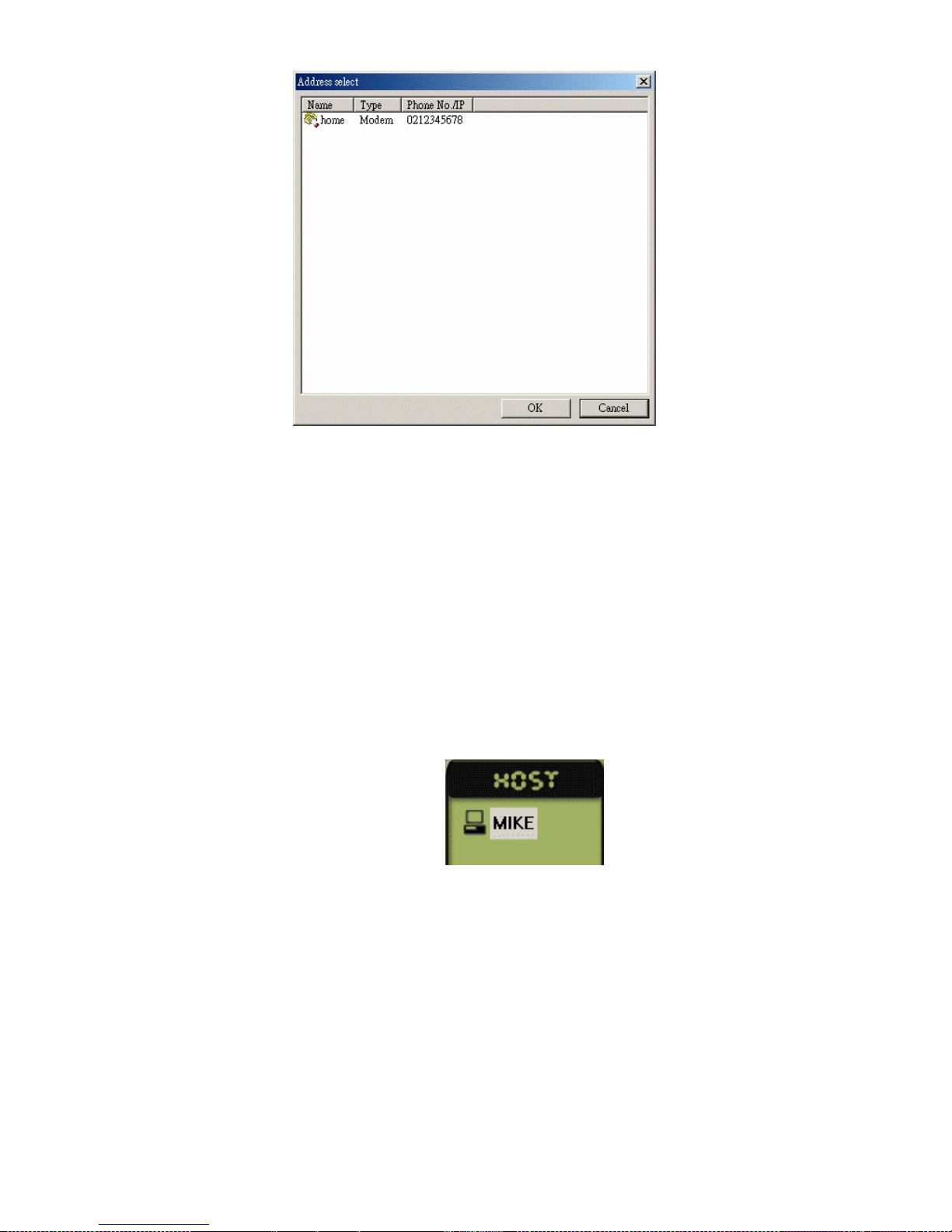
91
After connection is established, the Status field shows Connected and
Linked. Then double click the desired remote host on the Host menu of the
Cam SS XP Program to begin the remote monitoring.
Note: The setting for the password might be wrong if the status field
did not show Linked before it disconnected. Please verify the
user name and password.
Remark: The host names available on the Host menu are mainly from
those defined in the Identification Changes of My Network
Places (By clicking the right mouse button on My Network
Places icon) of the operating system. If the network card is not
installed the name will be the user name under the Windows
system.

92
9.3 Remote PTZ and Output Port Control Functions
One of the remote access functions is to provide PTZ and output port
control. After completing the above remote connection setup and access
auditing setup, users may double click on the desired remote host to switch
the current recording display on the Image Section to the remote one. The
PTZ control panel is then the remote host’s PTZ control panel. The remote
PTZ control panel only provides the control functions, not the setup
functions. For its operations, please refer to Chapter 7.2 and 7.3.

93
9.4 Other Remote Access Functions
According to different access auditing, the remote access provides different
control functions. Other major remote access functions are as follows:
1. To Unmask the detection area
Click on the desired remote camera, and then click the Unmask
button, , on the Camera Setup Section to cancel all the detection
areas. You can also set up a new detection area by dragging the mask
area on the remote images directly.
2. Video Capture card setup
If the remote Cam SS XP System is not in recording mode, you may
then change its board settings during this period of time. If the remote
system has already activated recording you must stop recording else
wise this function then is not usable.
3. Camera Setup
Click the button on the function panel; you may then change
the camera settings. Except the enable and disable camera functions
and alarm settings, all other functions are changeable.
4. Video Configurations
Click the Video Configuration button on the Camera Setup

94
Section to change the remote video configuration as desired.
9.5 Remote Monitoring Only
Under remote monitoring, the following will be shown:
Users will need to select the desired camera for recording or not recording.
After clicking the Ok button, the system will then transmit the images to the
local system’s image section for display or record as defined.

95
9.6 Examples for remote connections
When using the TCP/IP protocol for remote monitoring, (includes LAN,
Internet or Intranet), a Cam SS Server system is needed for connection.
After connection a user can easily connect to other systems for monitoring.
The Cam SS Server should be easily accessed and connected in the
network, and with the automatic server connection function for Cam SS XP
program, a fixed computer address is necessary when connecting to the
Cam SS Server to minimize connecting difficulties.
Assume there are 2 systems, settings as follow.
1. System A: (IP address: 192.168.16.18)
- Video Capture Card installed.
- Running Cam SS XP and Cam SS Server programs.
- User’s name is aaaa and password is aaaa
2. System B: (IP Address: 192.168.16.121)
- Using Cam SS XP programs
- User’s name is 1111 and password is 1111
■ Cam SS Server setup
Starts the Cam SS Server program on system A. Selects the user’s
information in the folder. Selects add 2 new users under the name and
password of aaaa and 1111 as follows.

96
■ Cam SS XP Setup.
1. System A
- Starts the Cam SS XP program under the name and password of
aaaa.
- Enter the setup, select the user settings, and add a user
name and password of 1111. (This password is used to check
whether the user is authorized for remote connection.)
- Chose the address book setting in the setup, add a new IP address
of 192.168.16.18 for server under any name.
- Enter for connection. Chose to connect using TCP/IP.
Double click on the server name in the address book. When
system has connected with the server, a connected will be shown.
2. System B
- Start the Cam SS XP program under the name and password of
1111.
- Chose the address book setting in the setup, add a new IP address
of 192.168.16.18 for server under any name.
- Enter the for connection. Chose to connect using TCP/IP.
Double click on the server name in the address book. When
system has connected with the server, a connected will be shown.
- User will then be able to find the system name for system A from
the host in the control panel.
- Double click on System A to display the divided picture. Click
the record button to select weather record or to monitor
without recording.
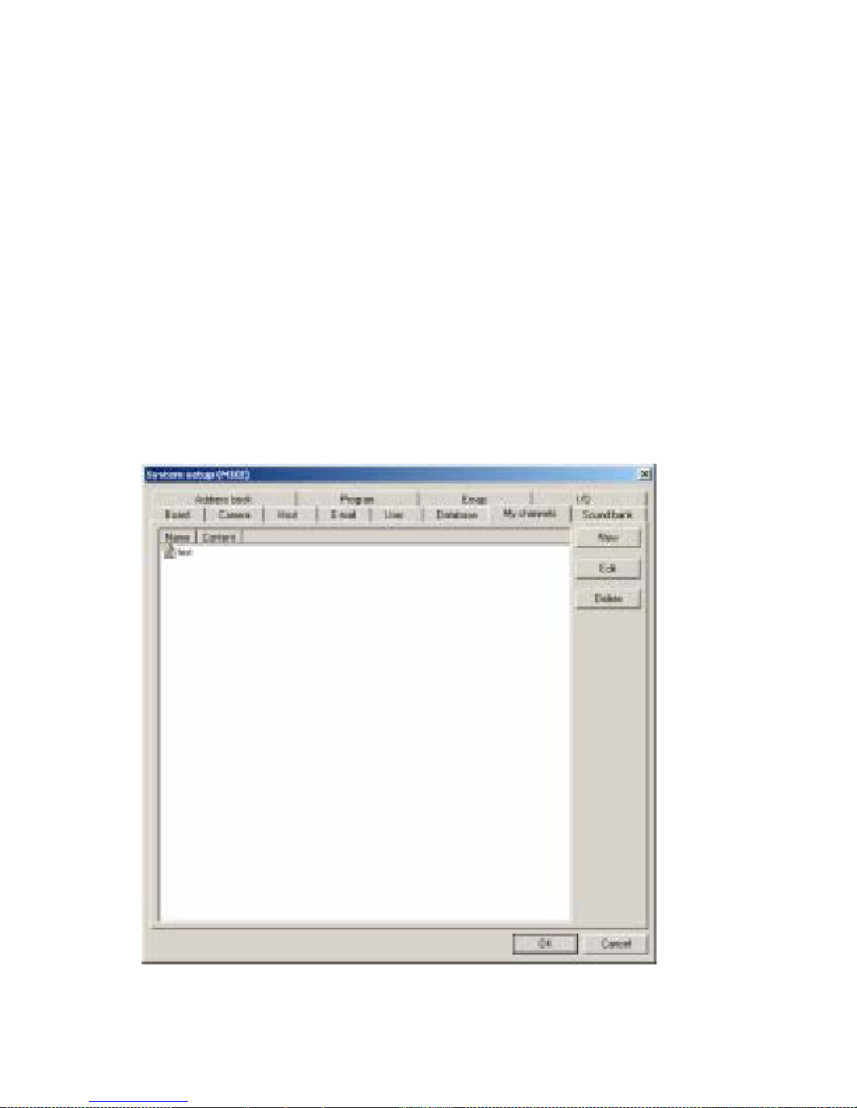
97
10.0 Additional Features Included in This Release
My Channels
Under the system setup function select the My Channels tab, you can then
monitor the appointed cameras from the same screen. Using this function,
you can then select the camera images that you want to monitor from the
hosts that are connected. You can arrange these camera’s in any desired
order for viewing. A maximum of 16 images can be displayed on the same
screen simultaneously. On the control panel, change to “My Channels”
mode; selectthe different name set to change to monitor predefined
combinations of cameras.
Note:
1. You will have to have the authorization from the remote host.
(Please refer to Chapter 3.5)
2. Using “My Channels” mode to monitor remote cameras, is much like
regular remote monitoring.
The setting is displayed as follows.

98
3.7.1 New “My Channels”
Select New to add a My Channels for monitoring as follows:
- Name: Name used to setup My Channels combination
- Content: No function
- Split screen: It is used to select the split screen that you want to display.
(The number of the camera images), it can be distinguish into 3
combinations of 4 divisions, 9 divisions and 16 divisions. The cameras
correspondence positions are different under different divisions. Please be
aware of it. 4 divisions: A, B, E and F 9 divisions: A, B, C, E, F, G, I, J, and
K. 16 divisions: All 16 positions from A-P.
- Host: The entire connected host name will be shown here.
Select the host name in the appointed position to display
the camera images under this host in this position. When setting this,
remote hosts have to be under connected status.
- Camera: After the setting of the host, the entire cameras name from
the selected host will be show here. Select the camera to be
monitored under this position. If the host has not been
selected, no selection will be available.
- Content: You can put in remarks for this position for better
camera information. After all settings are finished click OK to add a new
My Channels
setting.

99
3.7.2 Edit My Channels
Select the name of the My Channels for editing. Click the Edit button
to edit the appointed My Channels.
3.7.3 Delete My Channels
Select the name of the My Channels to be deleted. Click the Delete
button to delete this My Channels setting.
3.7.4 My Channels operation
You can switch to the My Channels operation panel by clicking or
the panel will then change from Host panel to My Channels panel as
follows:
When double clicking the My Channels name set (My Channels function
allows the setting of one or more different monitoring combinations.
After giving the monitoring combination a name, all the combination names
will be display here), the screen will then display the
division images (4 divisions, 9 divisions and 16 divisions) set under the
My Channels. Click the button, Cam SS XP will then begin
remote
monitoring according to the set hosts and cameras. Click the
button; the cameras from the remote host will be stopped.
To change to other My Channels settings simply double click the left
 Loading...