

Vision & Control Pictor M1606, 4-20-193, 4-20-194, pictor M41/EL Instructions For Use Manual
Instructions for Use
pictor M1606
Intelligent Camera
999.994.256.10-en-1.4
© Vision & Control GmbH 2014

pictor M1606
Impress
Publisher / Manufacturer Vision & Control GmbH
Mittelbergstraße 16
98527 Suhl, Germany
Telephone: +49 (0) 3681 / 79 74-0
Telefax: +49 (0) 3681 / 79 74-33
www.vision-control.com
Name of the document 999.994.256.10-en-1.4
Date of first issue 16.05.2014
Date modified 06.10.2014
Copyright © Vision & Control GmbH 2014
Copyright
It is forbidden to pass this document on to third parties, reproduce and
communicate its contents in as far as this has not been expressly authorized.
Offenders will be liable for damages.
All rights are reserved with respect to patent, utility sample and design patent
registrations, as well as for rights of use within the scope of copyright.
vicotar®, vicolux®, pictor®, vicosys® and vcwin® are registered trademarks of
Vision & Control GmbH.
The products and brand names of other manufacturers or suppliers are
mentioned for information only.
© Vision & Control GmbH 2014 999.994.256.10-en-1.4 2

pictor M1606
Validity
This manual is valid for the following devices:
Device Order no. Description
pictor M1606/E 4-20-193 1/3"CCD, 640x480, 63fps, mono, IR
cut filter, SVGA-Out
pictor M1606/E 4-20-194 1/3"CCD, 640x480, 62fps, mono,
broadband filter, SVGA-Out
3 999.994.256.10-en-1.4 © Vision & Control GmbH 2014

pictor M1606
Table of Contents
1. Important Information.................................................................................. 6
1.1. Information about the instructions of use.................................................... 6
1.2. Conventions of presentation........................................................................7
1.3. Presentation of Safety Instructions............................................................. 9
1.4. Proper and intended use...........................................................................10
1.5. Improper Use.............................................................................................11
1.6. Qualified Personnel................................................................................... 12
1.7. Warranty and liability................................................................................. 12
2. Safety Instructions..................................................................................... 13
2.1. Safe Handling of the Device..................................................................... 13
2.2. Environmental Protection.......................................................................... 14
3. Scope of Delivery and Accessories......................................................... 15
3.1. Scope of Delivery...................................................................................... 15
3.2. Accessories................................................................................................16
4. Product Description................................................................................... 19
4.1. Devices Views........................................................................................... 19
5. Product Data............................................................................................... 21
5.1. Interfaces................................................................................................... 23
5.1.1. Digital I/O-Interfaces.....................................................................23
5.1.2. Ethernet interface......................................................................... 24
5.1.3. RS232 interface............................................................................25
5.1.4. Trigger interface........................................................................... 26
5.2. Conditions for Operation, Storage and Transport..................................... 28
6. Operation software vcwin pro...................................................................29
6.1. System Requirements............................................................................... 29
6.2. Installing, Starting and Updating operating software vcwin pro................. 30
7. Commissioning........................................................................................... 31
7.1. Unpacking.................................................................................................. 31
7.2. Mounting.................................................................................................... 32
7.3. Connecting.................................................................................................34
7.3.1. Operating Voltage Supply............................................................ 34
7.3.2. Connecting the PLC/Power cable................................................ 35
7.3.3. Connecting the Ethernet cable..................................................... 38
7.3.4. Connecting the RS232 cable....................................................... 39
© Vision & Control GmbH 2014 999.994.256.10-en-1.4 4

pictor M1606
7.3.5. Connecting the trigger cable........................................................ 40
7.3.6. Connecting the video cable..........................................................41
7.3.7. Connecting vicolux lighting...........................................................42
7.3.8. Connecting the Power supply...................................................... 44
8. Operation..................................................................................................... 45
8.1. Switching On and Off (Ready for Operation)............................................ 45
8.2. Operation from the Software Interface...................................................... 45
8.2.1. First steps.....................................................................................45
8.2.2. Interface Settings......................................................................... 46
8.2.3. Connect to the operation software............................................... 48
9. Maintenance and Service.......................................................................... 49
9.1. Maintenance.............................................................................................. 49
9.2. Service....................................................................................................... 50
10. Decommissioning..................................................................................... 51
10.1. Disconnect............................................................................................... 51
10.2. Dismount..................................................................................................52
11. Disposal..................................................................................................... 53
11.1. Disposal................................................................................................... 53
12. Appendix....................................................................................................54
12.1. EC Declaration of Conformity..................................................................54
12.2. Technische Zeichnungen.........................................................................55
12.3. Spectral sensitivity...................................................................................56
13. Indexes.......................................................................................................57
13.1. List of Figures..........................................................................................57
13.2. ................................................................................................................. 58
14. .................................................................................................................... 62
5 999.994.256.10-en-1.4 © Vision & Control GmbH 2014

pictor M1606
Important Information
1 IMPORTANT INFORMATION
1.1 Information about the instructions of use
This document contains technical information, important instructions for correct
installation, commissioning and use, as well as product information which were
up-to-date at the time of going to press.
Using this document makes it easier for you to familiarise yourself with the
device and avoid malfunctions caused by improper operation.
Following the instructions of use:
•
Helps to avoid risks
•
Increases the reliability of the operation of the device
•
Lengthens the service life of the device
•
Reduces repair costs and downtimes
The instructions of use and the rules and regulations applicable at the place of
used must be observed.
Storage
To ensure a save and proper application, please read the instructions of use
carefully and keep for future reference.
© Vision & Control GmbH 2014 999.994.256.10-en-1.4 6

pictor M1606
Important Information
1.2 Conventions of presentation
The formatting and the symbols in this document help you to use the
instructions of use and the device quickly and safely.
Product name
The instructions of use are valid for the products listed at the beginning. If not
referred to expressly by the specific product name, the products described are
referred to as "devices".
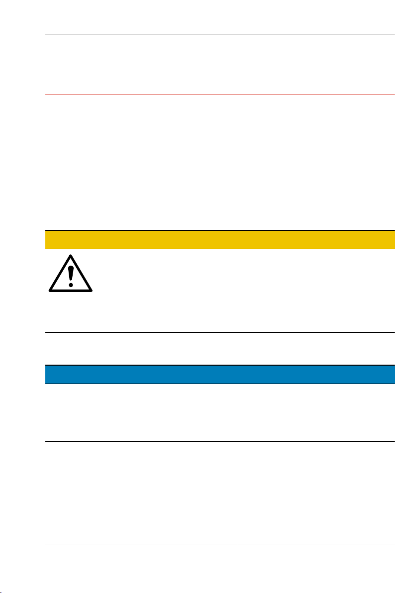
Advice
ADVICE
Indicates tips for users and useful additional information.
Enumeration
Indicates a listing of issues or possibilities:
Heading or topic of the enumeration
•
Example list item 1
•
Example list item 2
Operating steps
Listing of work steps, the given order of which must be followed. Numbering
starts at 1. for each individual sequence.
1. Example work step 1
Result work step 1
2. Example work step 2
Cross-references
Cross-references help you to make quick reference to particular sections of the
manual, providing valuable supplements of information. The cross-reference
shows you the page of the relevant section. Example: see "Conventions of
presentation", Page 7
7 999.994.256.10-en-1.4 © Vision & Control GmbH 2014

pictor M1606
Important Information
Links
Links lead to documents outside the instructions for use. Expressly, no
guarantee or liability is accepted for the accuracy and security of these
documents (such as Internetpages). Links are only active in online-help and
the PDF version and with a connection to the Internet. Example: www.vision-
control.com
Spelling
Commands, menus and dialogues are highlighted in bold. The spelling Utilities
indicated the menu Utilities.
References to subordinate entries are indicated by arrows.The spelling
Utilities > I/O Test indicates the command I/O Test in the Utilities menu.
The character formatting TEXT Indicates instructions, commands, and names
that you need to enter as shown.
Buttons are marked with square brackets. [OK] indicates the OK button.
Images and Tables
Figures and tables shown as such are numbered consecutively. Individual
details in figures are marked by item numbers and lines. Each item number is
explained in the legend accompanying the figure.
© Vision & Control GmbH 2014 999.994.256.10-en-1.4 8
pictor M1606
Important Information
1.3 Presentation of Safety Instructions
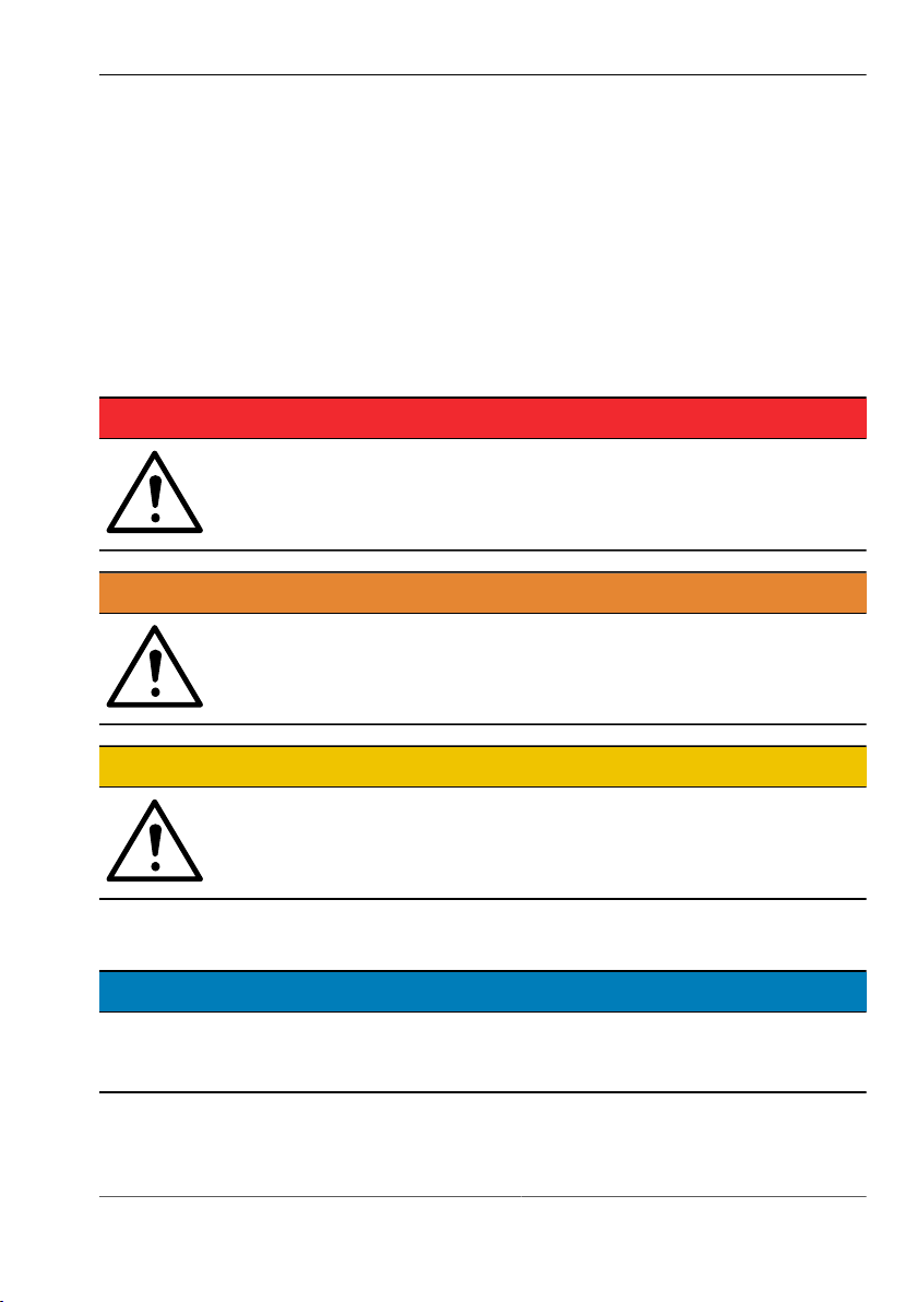
Each safety instruction is introduced by a key word and colour highlighted.
The key word indicates the degree of danger. The danger and its cause are
described, and then the measures to prevent conceivable consequences of the
danger. These measures must be taken.
Level of risk
DANGER
This key word indicates an imminent danger with high risk,
resulting in severe injuries or death if not avoided.
WARNING
This key word indicates a hazardous situation with medium risk,
possibly resulting in severe injuries or death if not avoided.
CAUTION
Signal word for a hazardous situation with low risk, resulting in
minor or medium injuries if not avoided.
Note on equipment damage
DAMAGE OF PROPERTY
Indicates a situation that may result in property damage, the impracticality of
the device or loss of data.
9 999.994.256.10-en-1.4 © Vision & Control GmbH 2014

pictor M1606
Important Information
1.4 Proper and intended use
The devices are designed as an industry-standard image processing system
for quality assurance and process automation.
The devices may only be used if they are in technically faultless condition and
only for their intended purpose, and only in accordance with the specifications
in this instructions of use by authorised operative personnel, who are aware of
the safety rules and hazards.
Areas of application
Use for the intended purpose is regarded as use in enclosed spaces for quality
assurance and process automation in the following industries:
•
Automotive
•
Mechanical engineering
•
Electrical engineering
•
Plastics industry
•
Solar industry
•
Packaging industry
•
Robotics
•
Pharmacy
•
Food industry
•
Automation technology.
The device can only function correctly and safely if it is stored, transported and
installed correctly, and operated carefully.
If the device is planned to be used for any other purpose or in a different
environment, the express authorisation of the manufacturer must be obtained
in advance. Any modifications or adaptations required may only be made by
the manufacturer.
© Vision & Control GmbH 2014 999.994.256.10-en-1.4 10

pictor M1606
Important Information
1.5 Improper Use
All unintended use and all device-related activities not described in this
operating manual is to be deemed as unauthorised misuse outside the legal
limits of indemnity of the manufacturer
Improper usage
Reasonably foreseeable misuse is:
•
Non-compliance with the instructions for use,
•
Faulty operation,
•
Operating by personnel not qualified or instructed,
•
Operating the device if it is not in a proper technical condition,
•
Operating the device in ambient conditions differing from the corresponding
specifications in the instructions of use
•
Operating the device with voltages differing from the corresponding
specifications in the instructions of use,
•
Using spare parts which are not original parts from the manufacturer,
•
Using incompatible accessory components,
•
Improper maintenance and repair works,
•
Unauthorised modifications to the device.
11 999.994.256.10-en-1.4 © Vision & Control GmbH 2014

pictor M1606
Important Information
1.6 Qualified Personnel
The device may only be assembled, commissioned, operated, maintained,
installed, set up, cleaned, repaired and transported by qualified skilled
personnel.
Qualified personnel
A qualified person is deemed to be someone who has been trained and
instructed for his/her activities with the device, and who has proven his/her
capability to the purchaser. The operating personnel must be authorised by the
purchaser for those activities at the device.
For the installation and operation of the device, the skilled personnel must
know and comply with the applicable guidelines and standards for handling
control equipment, electrical installations and working materials.
1.7 Warranty and liability
The contents of this document have been checked carefully and correspond to
current legislation and best practise at the time of going to press.
However, the manufacturer shall not be liable for any damage arising from the
use of this edition of the manual, and rejects any warranty derived therefrom.
Within the bounds of the legal requirements, the manufacturer shall only
be responsible for the technical safety characteristics of the device if the
maintenance, repairs and modifications to the device are performed by himself
or by authorised skilled personnel in accordance with his instructions.
Loss of warranty
The manufacturer shall accept no liability or warranty in the event of improper
use, opening of the device or incorrect maintenance.
© Vision & Control GmbH 2014 999.994.256.10-en-1.4 12
pictor M1606
Safety Instructions
2 SAFETY INSTRUCTIONS
Read the following applicable safety instructions carefully and completely.
Follow the instructions for your own safety, the safety of other people, and to
avoid damage to the device and the connected technical equipment. Hazards
going beyond the general safety instructions are referred to separately at the
relevant points in this manual.
2.1 Safe Handling of the Device
Electric shock
CAUTION
Risk of injury due to electric shock.
•
Before starting work on the device, disconnect it from the
operating voltage supply.
•
Follow all applicable safety regulations for the preparation
and operation of electrical devices.
Short circuit
DAMAGE OF PROPERTY
Destruction of the device as a result of a short circuit at the outputs.
•
Ensure that the connections are made with the correct polarity.
•
Do not overload the outputs (heat generation).
13 999.994.256.10-en-1.4 © Vision & Control GmbH 2014

pictor M1606
Safety Instructions
Electrostatic discharge
DAMAGE OF PROPERTY
Damage to semiconductor components and modules caused by
electrostatic discharge.
•
Do not open the device! Sensitive electronic components and modules
can be destroyed by unauthorised interference. Opening the device leads
to loss of warranty.
Transport damage
DAMAGE OF PROPERTY
Damage to the device as a result of improper transport.
•
Ship the device only in its original or adequately padded packaging.
•
Unscrew the lens and accessories before transporting the device, and
attach and close all covers and lids.
•
Do not allow the device to fall.
2.2 Environmental Protection
Conservation of nature is one of our major tasks. Properly disposed devices
avoid negative impacts on human beings and the environment and allows
reusing our precious resources.
Recycling
To dispose of the device in a manner that will not harm the environment follow
the instructions on "Disposal", Page 53.
© Vision & Control GmbH 2014 999.994.256.10-en-1.4 14

pictor M1606
Scope of Delivery and Accessories
3 SCOPE OF DELIVERY AND ACCESSORIES
Power supply and communication cables are required to operate the device.
Because of the many possible configurations, the cables are listed in the
accessories rather than included in the scope of delivery.
Please contact the manufacturer regarding lenses and lighting components
suitable for your field of application, or select them yourself at www.vision-
control.com.
3.1 Scope of Delivery
Designation Quantity
Device pictor M1606 1 x
Product DVD with:
•
Operating software vcwin pro
•
Instructions for use pictor M1606 as PDF
•
Instructions for use vcwin pro as PDF
•
Accesories technical data sheets as PDF
Instructions for use pictor M1606 as A5 book 1 x
Table 1: Scope of delivery
15 999.994.256.10-en-1.4 © Vision & Control GmbH 2014
1 x

pictor M1606
Scope of Delivery and Accessories
3.2 Accessories
Description Lenght Order no.
PLC/power cable, 12-pin HIROSE socket /
open cable end
PLC/power cable, 12-pin HIROSE socket /
open cable end
PLC/power cable, 12-pin HIROSE socket /
open cable end
Table 2: Accessories PLC/power cable
Description Lenght Order no.
Ethernet cable, 6-pin HIROSE plug / RJ45
plug
Ethernet cable, 6-pin HIROSE plug / RJ45
plug
Ethernet cable, 6-pin HIROSE plug / RJ45
plug
Table 3: Accessories Ethernet cable
5 m 4-40-223
10 m 4-40-224
25 m 4-40-225
5 m 4-40-203
10 m 4-40-204
20 m 4-40-205
© Vision & Control GmbH 2014 999.994.256.10-en-1.4 16

pictor M1606
Scope of Delivery and Accessories
Description Lenght Order no.
SVGA cable for monitor, 10-pin HIROSE
5 m 4-40-240
plug / 15-pin Sub-D socket
SVGA cable for monitor, 10-pin HIROSE
10 m 4-40-241
plug / 15-pin Sub-D socket
SVGA cable for monitor, 10-pin HIROSE
25 m 4-40-242
plug / 15-pin Sub-D socket
Table 4: Accessories SVGA cable for monitor
Description Lenght Order no.
V24 serial cable C4 (RS232), 6-pin HIROSE
5 m 4-40-181
plug / 9-pin Sub-D socket
V24 serial cable C4 (RS232), 6-pin HIROSE
10 m 4-40-182
plug / 9-pin Sub-D socket
V24 serial cable C4 (RS232), 6-pin HIROSE
25 m 4-40-183
plug / 9-pin Sub-D socket
Table 5: Accessories V24 serial cable C4 (RS232)
Description Lenght Order no.
Trigger cable, 6-pin HIROSE plug / open
5 m 4-40-200
cable end
Trigger cable, 6-pin HIROSE plug / open
10 m 4-40-201
cable end
Trigger cable, 6-pin HIROSE plug / open
25 m 4-40-202
cable end
Table 6: Accessories Trigger cable
17 999.994.256.10-en-1.4 © Vision & Control GmbH 2014

pictor M1606
Scope of Delivery and Accessories
Description Quantity Order no.
Key-Pad, incl. V24 serial cable C4 (RS232),
1 4-40-207
5 m, for the monitor menu
Key-Pad, without cable 1 4-40-204
Key-Pad, V24 serial cable C4 (RS232), 5 m 1 4-40-208
Table 7: Accessories Key-Pad
Description Quantity Order no.
Power supply, 24V DC/0.63 A, 12-pin
1 4-40-209
HIROSE-socket / 230V AC power plug
Table 8: Accessories Power supply
Properties of cable
You will find more detailed technical information about the cables on the data
sheets in the product catalog under www.vision-control.com or on the Product
DVD.
© Vision & Control GmbH 2014 999.994.256.10-en-1.4 18
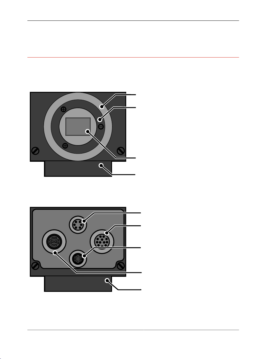
4 PRODUCT DESCRIPTION
Holder for filter
C-Mount lens connection
Imager
Mounting block
Video
LAN
Trig.
I/O
Monitor interface
Ethernet interface
PLC/Power interface
Trigger-/RS232 interface
Mounting block
4.1 Devices Views
Front view
Image 1: Front view
pictor M1606
Product Description
Rear view
Image 2: Rear view
19 999.994.256.10-en-1.4 © Vision & Control GmbH 2014

pictor M1606
Type: pictor M1606E
No.: E6380152
98527 Suhl, Germany
Vision & Control
Label
2 x M6 thread
1 x 1-32 UN2A thread
Product Description
Bottom view
Image 3: Bottom view
© Vision & Control GmbH 2014 999.994.256.10-en-1.4 20

5 PRODUCT DATA
Technical Data
Image Sensor
pictor M1606
Product Data
Device
Order number
Sensor 1/3" CCD, global shutter, progressive scan
Type mono
Filter IR cut filter broadband filter
Number of pixels 640 x 480
Pixel size 7.4 µm x 7.4 µm
Sensor size 5.79 mm x 4.89 mm
max. Frame rate 63 fps
Shutter 5 µs to 8 s
Processor
Device
Order number
Processor 3200 MIPS, 400 MHz Texas
pictor M1606
4-20-193
pictor M1606
4-20-193
Instruments TMS320C64xx
pictor M1606
4-20-194
Sony ICX424AL
pictor M1606
4-20-194
RAM 64 MB SDRAM
ROM 4 MB Flash-EPROM for programs and data
Storage media internal 1 GB SD card for user data
21 999.994.256.10-en-1.4 © Vision & Control GmbH 2014

pictor M1606
Product Data
Interfaces
Device
Order number
Communication 1 x RS232, 1 x Ethernet, 1 x TTL Trigger
Digital I/Os 4 x Digital IN, 4 x Digital OUT
Video out SXGA Monitor 800 x 600
General
Device
Order number
Housing material Aluminium alloy
Mounting At bottom: mounting block with 2 x M6 thread
Lens mount C-Mount
Dimensions / Weight 110 mm x 50 mm x 35 mm / 400 g
Protection class IP50
pictor M1606
4-20-193
pictor M1606
4-20-193
(outside) and 1 x 1/4" UNC thread (centre)
pictor M1606
4-20-194
pictor M1606
4-20-194
© Vision & Control GmbH 2014 999.994.256.10-en-1.4 22

5.1 Interfaces
Video
LAN
Trig.
I/O
LAN / Ethernet interface
PLC and power interface
Trigger, RS232 or Key-Pad interface
Video-Out (SVGA/SXVGA)
Overview of Interfaces
Image 4: Overview of interfaces
5.1.1 Digital I/O-Interfaces
pictor M1606
Product Data
The digital I/O interfaces are only available if the device is connected via the
Power/ PLC cable. In this case, the device is connected to the digital inputs
and outputs of a control unit and to the voltage supply.
Parameters Digital inputs
Parameter Min Nom Max
Number of inputs 4
Input voltage (DC) 0 V 24 V 28 V
Input current at 24 V DC 3.5 mA
Input voltage Low (DC) 0 V
Input voltage High (DC) 8 V 28 V
Overvoltage protection present
23 999.994.256.10-en-1.4 © Vision & Control GmbH 2014

pictor M1606
Product Data
Parameter Digital Outputs
Parameter Min Nom Max
Number of outputs 4
Power supply* 9.8 V 24 V 28 V
Switched potential power supply
Output current per output 500 mA
Output current all outputs 1 A
Switching power 24 V DC, 500 mA 12 W *
Protection against short circuit present
* external via Pin 1 and Pin 9 Digital IN
5.1.2 Ethernet interface
The device has an Ethernet interface for communicating with a host computer
or network.
•
Manage up to 16 simultaneous TCP / IP connections
•
Server port 8500 (initialization with vcwin pro)
•
Data rate: 100 Mbit
IP configuration in the as-supplied state
The device first attempts to have an IP address assigned from a DHCP. If an IP
address is not assigned by a DHCP server, the device has to be configured as
follows:
•
Static configuration
•
IP address 192.168.0.65
•
Subnet mask 255.255.255.0
•
Gateway 192.168.0.254
© Vision & Control GmbH 2014 999.994.256.10-en-1.4 24

pictor M1606
Product Data
5.1.3 RS232 interface
The device has a RS232 interface for serial communication with a process
control system (PLC, computer). The baud rate is set in the factory to 9.600
kbit/s. It can be adjusted from the software user interface.
The device can be parameterised with vcwin pro via the RS232.
The sending of measured values via the RS232 has to be activated /
parameterised by using of the vcwin pro software.
Parameters RS232 interface
Parameter Min Nom Max
Quantity 1
Baud rate 9.6 kbit/s 115.2 kbit/s
Protocol depends on the software used
Number of Bits 8
Number of stop-bits 1
Parity none
Flow control none
Galvanic isolation present
Key pad
For operation via the monitor menu the key pad (accessory) can be connected
to the RS232 interface. The power supply of the key pad is done automatically
by the device using the D-sub connector of the connecting cable. For details on
the key pad, please refer to the corresponding data sheet.
25 999.994.256.10-en-1.4 © Vision & Control GmbH 2014

pictor M1606
Product Data
5.1.4 Trigger interface
The device has a special trigger interface, a dedicated fast TTL trigger input
(for use as image capture trigger) and a fast TTL trigger output (Strobe
Trigger).
Both signals are very fast and have a very low signal to noise ratio, it is
recommended to keep the cable as short as possible. Use only shielded cables
for this purpose.
Parameters Trigger interface
Parameter Min Nom Max
Quantity 1
Output voltage 7 V DC
Output current 50 mA
Switching level
Input voltage Low 0 V DC 0.8 V DC
Input voltage High 2 V DC 5 V DC
Output voltage Low 0 V DC 0.4 V DC
Output voltage High 2.4 VDC 5 V DC
ADVICE
Neither the trigger input is nor the trigger output has an in-built in photo
coupler.
Ensure that the electrical specifications of this section are met and provide
galvanic isolation to trigger input and output if necessary.
© Vision & Control GmbH 2014 999.994.256.10-en-1.4 26

pictor M1606
Product Data
ADVICE
Input and output are not protected against over current.
The output is neither protected against short circuit nor reverse voltage
spikes from inductive loads.
Block diagram of trigger input
Image 5: Trigger input NPN
Image 6: Trigger input PNP
27 999.994.256.10-en-1.4 © Vision & Control GmbH 2014

pictor M1606
Product Data
Block diagram of trigger output
Image 7: Trigger output
5.2 Conditions for Operation, Storage and Transport
The following ambient conditions for operation, storage and transport must be
maintained:
Conditions that must be maintained
Ambient conditions Operation Storage and transport
Temperature 0 °C to + 50 °C - 20 °C to + 60 °C
Air humidity 20 % to 80 % 20 % to 90 %
Condensation water not permissible not permissible
Observe the relevant specific instructions for accessories and connected
devices and components stated in the corresponding manuals and operating
instructions.
© Vision & Control GmbH 2014 999.994.256.10-en-1.4 28

pictor M1606
Operation software vcwin pro
6 OPERATION SOFTWARE VCWIN PRO
If the device is connected Ethernet interface, it can be immediately controlled,
parameterised and configured with the vcwin pro operation software.
The devices are parameterised with the vcwin pro operation software via the
Ethernet interface (recommended) or the RS232 interface. The software also
enables test sequences to be created.
6.1 System Requirements
Minimum requirements of the computer
•
Operating systems: Windows Vista, Windows 7, Windows 8.1- Both 32 and
64 bit versions (Windows RT is not supported)
•
DVD drive (for installation from DVD) or Internet connection (for installation
after download)
•
Minimum 1 GB free RAM
•
Monitor with a resolution of at least 800 x 600 pixels
•
Ethernet interface
•
Serial interface (optional for sending and receiving via RS232)
29 999.994.256.10-en-1.4 © Vision & Control GmbH 2014

pictor M1606
Operation software vcwin pro
6.2 Installing, Starting and Updating operating software vcwin pro
ADVICE
Administrator rights are required to install the operating software.
Installing vcwin pro
1. Insert the supplied DVD into the drive of the host computer
2. Select option "Open Autorun menu" or double click the "start.exe" file.
3. Select language.
4. Select menu item "Software".
5. Select the operating software vcwin pro and install on the computer by
clicking [Install]. Follow the instructions given by the installation program,
and change the target directory if desired.
The software also installs an optional icon on the Windows Desktop, and
creates entries in the start menu.
Starting vcwin pro
The operating software can be started by double clicking the icon on the
Desktop or by selecting it from the start menu. Registration is not required.
Updating vcwin pro
The software version which is current at the time of delivery is always supplied
with the device. There is no automatic update.
The operating software vcwin prois continually further developed to adapt and
extend its scope of functions to meet customer requirements. New versions of
the operating software can be downloaded from: www.vision-control.com.
© Vision & Control GmbH 2014 999.994.256.10-en-1.4 30

pictor M1606
Commissioning
7 COMMISSIONING
7.1 Unpacking
DAMAGE OF PROPERTY
Damage or destruction of the device caused by condensation and large
temperature differences!
•
Do not subject the device to large temperature fluctuations.
•
After storage and transport, allow the device to adjust slowly to the
ambient temperature at the place of use.
•
Do not open the lens cover during the acclimatisation (to prevent the
formation of condensation water).
ADVICE
Unpack the device in a dry, dust-free environment.
1. Lift the cardboard, together with the device, out of the carton.
2. Fold out the tucked in sides on the bottom of the cardboard.
Loosening the film and forming an insertion pocket.
3. Remove the device out of the insection pocket.
4. Dispose the packing material (see "Disposal", Page 53).
31 999.994.256.10-en-1.4 © Vision & Control GmbH 2014

pictor M1606
Commissioning
7.2 Mounting
DAMAGE OF PROPERTY
Cable damaged by a bending radius that is too small and the lack of a
strain relief clamp.
•
Comply with the specified minimum bending radius.
•
Cables must generally be mounted with a strain relief clamp.
•
Use cables corresponding to the specification (see data sheet).
Mounting of cables
When mounting the cable to the device, hold the device and plug the cable into
the connector.
Mounting the device
To install the device, a mounting block with two tapped holes M6 and a 1-32
UN 2A thread is located at the bottom.
Distance between the tapped holes 25 mm
Maximum screwed-in depth 7 mm
Maximum tightening torque 10 Nm
Table 9: Properties of the tapped holes
© Vision & Control GmbH 2014 999.994.256.10-en-1.4 32

Mounting holes
17.5
30.0
42.5
25.0
M6 M61-32 UN 2A
17.5
28.5
55.5
8.0
pictor M1606
Commissioning
Image 8: Mounting holes for mounting the device
Mounting the Lens
1. Remove the protective film / cap.
2. Screw on the selected lens.
Working distance and recording range
The working distance, recording range and size of the image field are flexible
and dependent on the selected lens.
33 999.994.256.10-en-1.4 © Vision & Control GmbH 2014

pictor M1606
Commissioning
7.3 Connecting
The operating voltage is supplied via the PLC/Power cable or the power plug.
Communication takes place via the PLC/Power cable and/or Ethernet, RS232.
7.3.1 Operating Voltage Supply
The operating voltage is supplied through the PLC/Power Cable (accessories)
or the power supply (accessories).
When using the power supply, the digital I/O interfaces of the device can not be
used.
Requirements on the operating voltage source
•
protective earth contact,
•
earthing.
Parameter
Parameter Min Nom Max
Operating voltage 9 V 24 V 28 V
Current consumption at 24 V DC 125 mA 350 mA
Power consumption at 24 V DC 5.5 W
Table 10: Parameters of the operating voltage supply
ADVICE
The power supply of the camera and the power supply to the digital I/O
channels are separated internally.
© Vision & Control GmbH 2014 999.994.256.10-en-1.4 34

Connection of the operating voltage supply
IN GND
CAM PWR
+
2
3
Image 9: Connection of the operating voltage supply
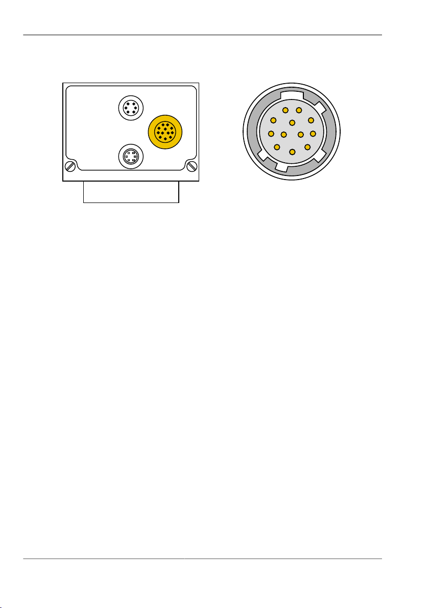
7.3.2 Connecting the PLC/Power cable
pictor M1606
Commissioning
Perform the following steps only in de-energiesed state.
1. Plug the 12-pin Hirose plug of the PLC/Power cable into the I/O socket on
the device.
2. Connect the open end of the PLC/Power cable to control unit.
35 999.994.256.10-en-1.4 © Vision & Control GmbH 2014
pictor M1606
LAN
Trig.
I/O
1
2
3
4
5
6
7
8
9
10
11 12
Commissioning
Image 10: PLC/Power cable
connection
Image 11: View: socket on camera
© Vision & Control GmbH 2014 999.994.256.10-en-1.4 36

Commissioning
Pin assignments PLC/Power cable
Pin Colour Assignment Open cable end
1 red 24 V PLC* + 24 V dig. input and output
2 red / blue +UB Operating voltage + 24 VDC
3 black GND Operating voltage GND
4 pink IN 2 Digital input 2
5 yellow OUT 4 Digital output 4
6 green OUT 3 Digital output 3
7 brown OUT 2 Digital output 2
8 white OUT 1 Digital output 1
9 grey / pink 24 V PLC* + 24 V dig. input and output
10 violet IN 4 Digital input 4
pictor M1606
11 blue IN 3 Digital input 3
12 grey IN 1 Digital input 1
* The PLC output voltage is separated from the supply voltage. There is a
common ground for PLC output voltage and supply voltage.
Table 11: Pin assignment PLC/Power cable
37 999.994.256.10-en-1.4 © Vision & Control GmbH 2014

pictor M1606
Video
LAN
Trig.
I/O
1
2
3
4
5
6
Commissioning
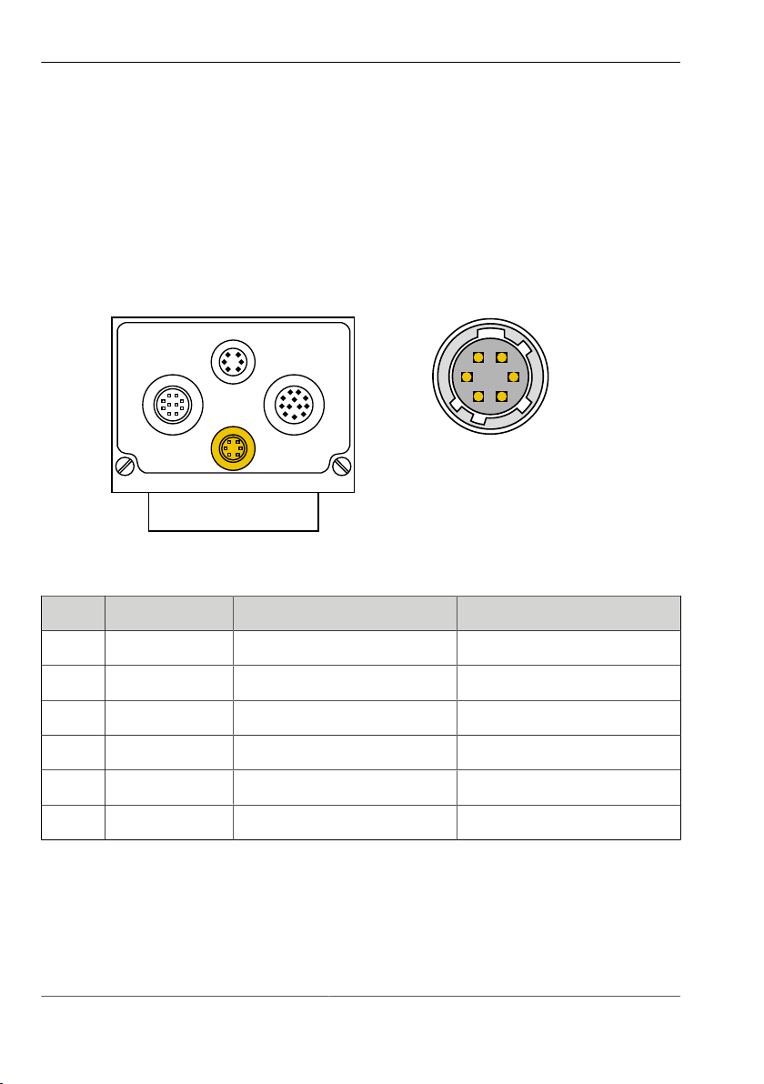
7.3.3 Connecting the Ethernet cable
Perform the following steps only in de-energiesed state:
1. Insert the 6-pin HIROSE plug of the Ethernet cable into the LAN socket on
the device.
2. Connect the RJ45 plug to a free Ethernet interface on the host computer or
the network.
Image 13: View: socket on camera
Image 12: Ethernet cable
connection
Pin assignment Ethernet cable
Pin Designation Description RJ45 plug pin
1 TX- Send data - 2
2 TX+ Send data + 1
3 NC not connected
4 NC not connected
5 RX- Received data- 6
6 RX+ Received data+ 3
Table 12: Pin assignment Ethernet cable
© Vision & Control GmbH 2014 999.994.256.10-en-1.4 38

pictor M1606
Video
LAN
Trig.
I/O
1
2
3
4
5
6
Commissioning
7.3.4 Connecting the RS232 cable
Perform the following steps only in de-energiesed state:
1. Insert the 6-pin HIROSE plug of the RS232 cable into the Trig. socket on the
device.
2. Plug the D-Sub plug into a free serial port (COM) of the process control
system or the key pad, and screw tight.
Pin assignment RS232 cable
Pin Signal Description D-Sub pin
1 TxD Send data 2
2 + 5 VDC Out Power + 5 V DC* *
3 GND Ground 5
4 RxD Receive data 3
5 Trigger Out Trigger output* *
6 +5 V TTL Trigger input* *
* Only for key pad.
Table 13: Pin assignment RS232 cable
39 999.994.256.10-en-1.4 © Vision & Control GmbH 2014
pictor M1606
Video
LAN
Trig.
I/O
1
2
3
4
5
6
Commissioning
7.3.5 Connecting the trigger cable
Perform the following steps only in de-energiesed state:
1. Insert the 6-pin HIROSE plug of the trigger cable into the Trig. socket on the
device.
2. Connect the open end of the trigger cable to control unit.
Pin assignment trigger cable
Pin Colour Assignment Open cable end
1 green RS232 TxD Out Send data
2 brown +5 V DC Out Power +5 V
3 white GND Ground
4 violet RS232 RxD Receive data
5 grey Trigger Out Output trigger
6 yellow +5 V TTL Input trigger
Table 14: Pin assignment trigger cable
© Vision & Control GmbH 2014 999.994.256.10-en-1.4 40

pictor M1606
Video
LAN
Trig.
I/O
9
8
7
6
5
4
3
2
1
10
Commissioning
7.3.6 Connecting the video cable
Perform the following steps only in de-energiesed state:
1. Insert the 10-pin Hirose plug of the video cable into the video socket on the
device.
2. Connect the 15-pin D-Sub plug with a monitor.
Image 15: View: socket on camera
Image 14: Video cable connection
Pin assignments video cable
Pin Signal Description Pin Signal Description
1 G GND Ground signal green 2 G OUT Signal green
3 R GND Ground signal red 4 R OUT Signal red
5 VS GND Ground Vertical Sync 6 VS OUT Vertical Sync
7 HS GND Ground Horizontal Sync 10 HS OUT Horizontal Sync
8 B GND Ground signal blue 9 B OUT Signal blue
Table 15: Pin assignments video cable
41 999.994.256.10-en-1.4 © Vision & Control GmbH 2014

pictor M1606
vicolux ®
+5 V
Trig. Out
Camera
+Trg.
-Trg.
vicolux ®
+5 V
Trig. Out
Camera
+Trg.
-Trg.
GND
R
Commissioning
7.3.7 Connecting vicolux lighting
Connecting a vicolux® lighting with TTL trigger via HIGH/LOW status transition
Image 16: Connection option HIGH/LOW edge
Connecting a vicolux® lighting with TTL trigger via LOW/HIGH status transition
Image 17: Connection option LOW/HIGH edge
© Vision & Control GmbH 2014 999.994.256.10-en-1.4 42

pictor M1606
vicolux ®
GND
Trig. Out
Camera
+ PLC
- PLC
+ 24 V
vicolux ®
Trig. Out
Camera
GND
R
+ PLC
- PLC
+ 24 V
Commissioning
Connecting a vicolux® lighting with 24 V PLC control and LOW/HIGH edge at
the Trigger Out
Image 18: Connection option with PLC and HIGH/LOW edge
Connecting a vicolux® lighting with 24 V PLC control and HIGH/LOW edge at
the Trigger Out
Image 19: Connection option with PLC and LOW/HIGH edge
43 999.994.256.10-en-1.4 © Vision & Control GmbH 2014

pictor M1606
Commissioning
7.3.8 Connecting the Power supply
ADVICE
When using the power supply (AC adapter), the digital I/O interfaces of the
device can not be used.
Perform the following steps only in de-energiesed state.
1. Plug the 12-pin HIROSE connector of the power supply into the I/O socket
on the device.
2. Plug the power supply into a socket.
© Vision & Control GmbH 2014 999.994.256.10-en-1.4 44

pictor M1606
Operation
8 OPERATION
8.1 Switching On and Off (Ready for Operation)
The device is switched on with the operating voltage supplied via the PLC/
Power cable.
Disconnecting the device from the operating voltage supply switches the device
off.
8.2 Operation from the Software Interface
ADVICE
To operate the device from the software, please read the corresponding
instructions of use for the operation software vcwin pro.
This also describes the scope of functions and test functions of the software.
8.2.1 First steps
1 Connect the device to a host computer (RS232 or Ethernet cable). See:
"Connecting the RS232 cable", Page 39 / "Connecting the Ethernet cable",
Page 38
2 Connect the device to a control monitor (optional). See: "Connecting the
video cable", Page 41
3 Connect the device with a 24 V DC power supply. See: "Connecting the
PLC/Power cable", Page 35
4 Start the operation software vcwin pro on the computer.
45 999.994.256.10-en-1.4 © Vision & Control GmbH 2014
pictor M1606
1
2
3
4
5
Operation
8.2.2 Interface Settings
Use Menu Communication > Interface to configure the interface for
communication between the host computer and the device.
Settings made here are used in every connection with vcwin pro.
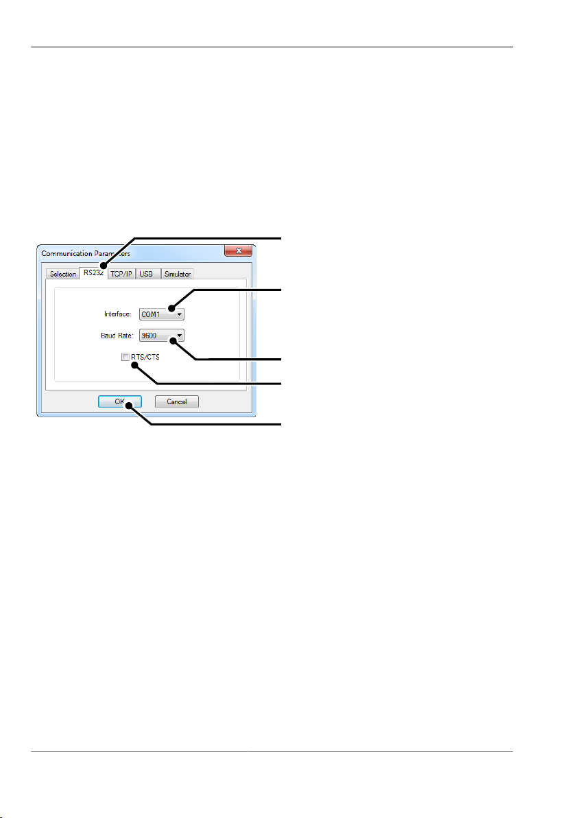
Serial connection with the device
Image 20: vcwin pro dialogue: Communication Parameters RS232
1. Switch to the RS232 tab.
2. Select the the COM interface of your computer.
3. Set the baud rate to 9600. After connecting the baud rate can be adjusted.
4. Deactivate RTS/CTS (Hardware handshake of the RS232 interface).
5. Click the [OK] button to accept the values.
The device can now be connected to vcwin pro.
© Vision & Control GmbH 2014 999.994.256.10-en-1.4 46
pictor M1606
1
4
2
3
5
Operation
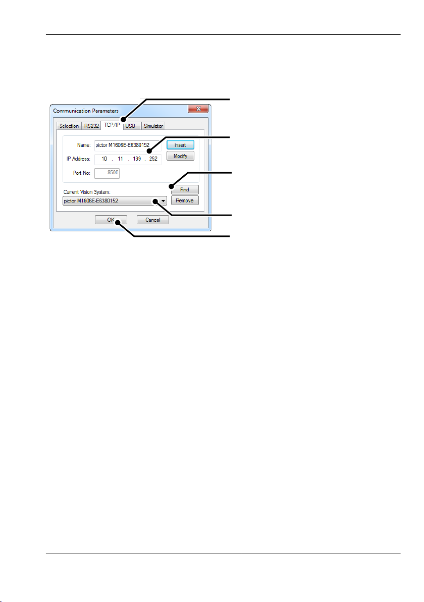
ICP/IP connection with the device
Image 21: vcwin pro dialogue: Communication Parameters TCP/IP
1. Switch to the TCP/IP tab.
2. With the [Search] button, all available devices, on the same subnet, are
displayed (UDP broadcast to all participants).
3. Select the appropriate device.
4. Optionally, you can also enter the name and IP address of your device.
5. Click the [OK] button to accept the values.
The device can now be connected to vcwin pro.
47 999.994.256.10-en-1.4 © Vision & Control GmbH 2014

pictor M1606
Operation
8.2.3 Connect to the operation software
Connect the device with the operation software vcwin pro via:
•
Menu: Communication > Connect
or
•
Toolbar
The initialisation of the host computer interface sets up a connection with the
device via vcwin pro. The Run Mode is interrupted and the system resources
are queried. vcwin pro uses the initialisation to recognise all the geometry
variables, results, contour buffer, counters, image memory pages and I/O
hardware available from the device connected. After initialising, the system is in
Command Mode and vcwin commands may be used.
© Vision & Control GmbH 2014 999.994.256.10-en-1.4 48

pictor M1606
Maintenance and Service
9 MAINTENANCE AND SERVICE
9.1 Maintenance
The device is maintenance-free. Depending on the operating environment, it
may have to be cleaned.
Cleaning the outer face
The housing can be cleaned according to the conditions applicable to the given
protection class.
Clean the outside with a damp cloth and a gentle cleanser.
Cleansers must not be applied directly to the housing, and the housing must
not be bathed.
Do not use any corrosive cleansers, such as lyes, MEK cleanser (methyl ethyl
ketone), benzine or similar substances!
The device must not be opened. The port sockets must be clean and dry
before the device is connected and brought into operation.
Cleaning the protective glass / filter
Do not scratch and keep dust and grease off the protective glass! Do not touch
the glass!
If it is heavily soiled, clean the protective glass with a cotton bud soaked in
ethyl, methyl or isopropyl alcohol. The alcohol must not be applied directly to
the protective glass.
Clean and care for the lenses as described in the guide for the relevant lens.
Cleaning by the manufacturer
The device can be sent to the manufacturer for cleaning (for a fee). Please
contact our Technical Support.
49 999.994.256.10-en-1.4 © Vision & Control GmbH 2014

pictor M1606
Maintenance and Service
9.2 Service
Technical Support
Please contact our Technical Support if you have any technical questions
concerning our products. Competent employees will deal with your problems
and questions.
We will be glad to be of service:
Monday to Thursday 8:00 to 17:00, and Friday 8:00 to 15:00.
Phone: +49 (0) 3681/ 7974 - 20
Defective device
If the device has a defect, the manufacturer can repair or exchange it. Please
contact your local sales partner or Technical Support.
Firmware update
The device can be sent to the manufacturer for a firmware update (for a fee).
Please contact our Technical Support.
© Vision & Control GmbH 2014 999.994.256.10-en-1.4 50

pictor M1606
Decommissioning
10 DECOMMISSIONING
ADVICE
The device is decommissioned in the same way as it was commissioned, but
in reverse order.
The order of the points "Disconnect" and "Dismount" is decided by the
accessibility of the device when mounted in the operating environment.
10.1 Disconnect
ADVICE
Only disconnect the device when it is not processing.
1. Disconnect the device from the operating voltage supply.
2. Disconnect communication:
°
Disconnect the PLC/power cable from the control unit.
°
Remove the RJ45 plug of the Ethernet cable from the host computer.
°
Remove the D-Sub plug of the RS232 cable from the process control
system.
°
Remove the D-Sub plug of the SVGA-cable from the monitor.
3. Disconnect all cables from the device.
51 999.994.256.10-en-1.4 © Vision & Control GmbH 2014

pictor M1606
Decommissioning
10.2 Dismount
1. Secure or hold the device firmly.
2. Unscrew the screws holding the device in the holder.
3. If applicable, unscrew the lens.
4. Put the cover on the lens mount.
© Vision & Control GmbH 2014 999.994.256.10-en-1.4 52

pictor M1606
Disposal
11 DISPOSAL
11.1 Disposal
The device and its accessories and packaging must be sent for
environmentally compatible recycling.
Do not throw electrical devices or tools into the household waste!
According to European Directive 2002/96/EC on waste electrical and electronic
equipment and its implementation in national law, unusable electric tools must
be collected separately, and sent for environmentally compatible recycling.
Disposal, including that of individual components, must also always be in a way
that does not harm the environment, that is it must be done in accordance with
the currently valid legal regulations.
Please contact the manufacturer, your local specialist dealer or the relevant
national authority for the proper disposal of old devices.
The electrical and electronic components must be sent to a specialist recycling
company or to the manufacturer for proper disposal.
53 999.994.256.10-en-1.4 © Vision & Control GmbH 2014

pictor M1606
Appendix
12 APPENDIX
12.1 EC Declaration of Conformity
Vision & Control GmbH
Mittelbergstraße 16
D-98527 Suhl, Germany
Representative: Dr. Jürgen Geffe, Managing director
We, Vision & Control GmbH Suhl, declare that the products described below
•
pictor M1606/E
have been manufactured in accordance with the following standards and
normative documents:
•
2004/108/EC – Electromagnetic compatibility
•
DIN EN 61000-6-2:2005 – Immunity for industrial environments
•
DIN EN 61326-1:2006 – Electrical equipment for measurement, control and
laboratory use
Suhl, 01.03.2013
© Vision & Control GmbH 2014 999.994.256.10-en-1.4 54

12.2 Technische Zeichnungen
Dimensions
pictor M1606
Appendix
Image 22: Dimensions
55 999.994.256.10-en-1.4 © Vision & Control GmbH 2014
pictor M1606
Appendix
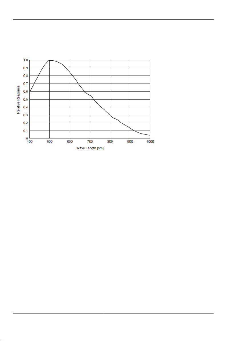
12.3 Spectral sensitivity
Image 23: Spectral sensitivity M1606/E
© Vision & Control GmbH 2014 999.994.256.10-en-1.4 56

pictor M1606
Indexes
13 INDEXES
13.1 List of Figures
Image 1: Front view....................................................................................19
Image 2: Rear view.................................................................................... 19
Image 3: Bottom view.................................................................................20
Image 4: Overview of interfaces.................................................................23
Image 5: Trigger input NPN....................................................................... 27
Image 6: Trigger input PNP........................................................................27
Image 7: Trigger output.............................................................................. 28
Image 8: Mounting holes for mounting the device ....................................33
Image 9: Connection of the operating voltage supply................................35
Image 10: PLC/Power cable connection...................................................... 36
Image 11: View: socket on camera..............................................................36
Image 12: Ethernet cable connection...........................................................38
Image 13: View: socket on camera..............................................................38
Image 14: Video cable connection............................................................... 41
Image 15: View: socket on camera..............................................................41
Image 16: Connection option HIGH/LOW edge...........................................42
Image 17: Connection option LOW/HIGH edge...........................................42
Image 18: Connection option with PLC and HIGH/LOW edge.....................43
Image 19: Connection option with PLC and LOW/HIGH edge.....................43
Image 20: vcwin pro dialogue: Communication Parameters RS232............ 46
Image 21: vcwin pro dialogue: Communication Parameters TCP/IP........... 47
Image 22: Dimensions.................................................................................. 55
Image 23: Spectral sensitivity M1606/E....................................................... 56
57 999.994.256.10-en-1.4 © Vision & Control GmbH 2014

pictor M1606
Indexes
A
Accessories...................................................................................................... 16
Air humidity .................................................................................................... 28
Ambient conditions.......................................................................................... 28
C
Communication.......................................................................................... 22, 34
Connecting....................................................................................................... 34
Connecting the interface................................................................................. 48
D
Decommissioning............................................................................................. 51
Devices Views................................................................................................. 19
Digital I/O-Interfaces........................................................................................ 23
Digital I/Os....................................................................................................... 22
Digital inputs.................................................................................................... 23
Digital Outputs................................................................................................. 24
Dimensions ..................................................................................................... 22
Dismount.......................................................................................................... 52
E
Electrostatic discharge.................................................................................... 14
Ethernet cable........................................................................................... 16, 38
Ethernet interface............................................................................................ 24
F
Frame rate....................................................................................................... 21
G
General............................................................................................................ 22
© Vision & Control GmbH 2014 999.994.256.10-en-1.4 58

pictor M1606
Indexes
H
Housing material.............................................................................................. 22
I
ICP/IP connection............................................................................................ 47
Image Sensor.................................................................................................. 21
Interfaces................................................................................................... 22, 23
K
Key pad........................................................................................................... 25
Key-Pad........................................................................................................... 18
L
Lens................................................................................................................. 33
Lens mount...................................................................................................... 22
M
Mounting.................................................................................................... 22, 32
N
Number of pixels............................................................................................. 21
O
operating voltage....................................................................................... 34, 45
Operating Voltage Supply................................................................................ 34
P
photo thread.................................................................................................... 32
Pixel size......................................................................................................... 21
PLC/power cable.......................................................................... 16, 34, 35, 45
Power supply............................................................................................. 18, 44
59 999.994.256.10-en-1.4 © Vision & Control GmbH 2014

pictor M1606
Indexes
Processor......................................................................................................... 21
Product name.................................................................................................... 7
Protection class............................................................................................... 22
R
Ready for Operation........................................................................................ 45
rigger cable...................................................................................................... 40
RS232 cable.................................................................................................... 39
RS232 interface............................................................................................... 25
S
Scope of Delivery............................................................................................ 15
Sensor.............................................................................................................. 21
Serial connection............................................................................................. 46
Shutter............................................................................................................. 21
storage............................................................................................................. 28
SVGA cable for monitor.................................................................................. 17
T
tapped holes.................................................................................................... 32
trademarks......................................................................................................... 2
transport........................................................................................................... 28
Trigger cable.................................................................................................... 17
Trigger interface............................................................................................... 26
V
V24 serial cable C4 (RS232).......................................................................... 17
vcwin
Interface configuration................................................................................. 46
vcwin pro......................................................................................................... 25
vicolux lighting................................................................................................. 42
video cable...................................................................................................... 41
Video out......................................................................................................... 22
© Vision & Control GmbH 2014 999.994.256.10-en-1.4 60

pictor M1606
Indexes
W
Weight.............................................................................................................. 22
Working distance............................................................................................. 33
61 999.994.256.10-en-1.4 © Vision & Control GmbH 2014

 Loading...