


Vision
Components
®
The Smart Camera People
VisiCube Manual
Operating Instructions for VisiCube Sensor Smart Cameras
Revision 1.0 August 2007
Document name: VisiCube.pdf
© Vision Components GmbH Ettlingen,
Germany

VisiCube Manual
II
Foreword and Disclaimer
This documentation has been prepared with most possible care. However Vision Components GmbH
does not take any liability for possible errors. In the interest of progress, Vision Components GmbH
reserves the right to perform technical changes without further notice.
Please notify
support@vision-components.com if you become aware of any errors in this manual or
if a certain topic requires more detailed documentation.
This manual is intended for information of Vision Component’s customers only. Any publication of this
document or parts thereof requires written permission by Vision Components GmbH.
Trademarks
Code Composer Studio and TMS320C6000, Windows XP, Total Commander, Tera Term, Motorola
are registered Trademarks. All trademarks are the property of their respective owners.
References
Since the VC4XXX smart camera family employs a TI processor, the programming environment and
functions for the VC20XX cameras can be used for this camera.
Further References under “Support + Download” on
www.vision-components.com:
„Support News“ – for up to date information on VC Software and Documentation.
„
Knowledge Base / FAQ“ - searchable Database with latest software developments, frequently asked
questions and demo programs.
“
Download Areas” for all documentation and Software downloads – refer to the following table:
Description Title on Website Download Area
Quick start Manual for VC cameras,
English Version
Getting Started VC Smart
Cameras
Registered User Area
Getting Started VC SDK TI
Schnellstart VC Handbuch –
Deutsche Version
Schnellstart VC Smart
Kameras
Registered User Area
Getting Started VC SDK TI
Introduction to VC Smart Camera
programming
Programming T utorial for
VC20XX and VC40XX Cameras
Registered User Area
Getting Started VC SDK TI
Demo programs and sample code
used in the Programming Tutorial
Tutorial_Code
Registered User Area
Getting Started VC SDK TI
VC4XXX Hardware Manual
VC4XXX Smart Cameras
Hardware Documentation
Public Download Area Hardware
Documentation VC Smart Cameras
VCRT Operation System Functions
Manual
VCRT 5.0 Software Manual
Registered User Area Software
documentation VC Smart Cameras
VCRT Operation System TCP/IP
Functions Manual
VCRT 5.0 TCP/IP Manual
Registered User Area Software
documentation VC Smart Cameras
VCLIB 2.0 /3.0 Image Processing
Library Manual
VCLIB 2.0/ 3.0 Software
Manual
Registered User Area Software
documentation VC Smart Cameras
The Light bulb highlights hints and ideas that may be helpful for a development.
This warning sign alerts of possible pitfalls to avoid. Please pay careful attention to sections
marked with this sign.
!
Author: Peter Neuhaus, VC Support,
mailto:support@vision-comp.com
© 1996-2007 Vision Components GmbH Ettlingen, Germany VisiCube.pdf

VisiCube Manual
III
Table of Contents
1 General Information 1
2 Special Features of the VisiCube Sensor Smart Camera 2
2.1 Main differences of VisiCube and VC4018 2
2.2 Lenses 2
2.3 LED Lighting 3
3 Technical Specifications VisiCube Smart Camera 4
4 VisiCube Interfaces 5
4.1 Power Supply / SPS IO Interface and Trigger interface 5
4.2 LAN / Ethernet Interface 6
4.3 Data / RS422 Interface 7
5 Order Numbers of VisiCube and Accessories 8
6 Programming of special VisiCube Features 9
6.1 Using PLC Inputs and Outputs 9
6.2 Capturing Images with a Hardware Trigger Signal 9
6.3 Using the RS422 Data Interface of the VisiCube 10
6.4 Using the Status LEDs 10
6.5 Using the LED Lighting 11
7 Maintenance 12
7.1 Cleaning 12
7.2 Repair 12
Appendix A: Dimensional Drawings of VisiCube A
Appendix B: Using the PLC_INT event B
© 1996-2007 Vision Components GmbH Ettlingen, Germany VisiCube.pdf

VisiCube Manual
1
1 General Information
VisiCube Sensor Smart Camera in its Compact Housing
The VisiCube camera is with its very compact form factor of only 65 x 45 x 45 mm and 170g one of the
smallest Smart Cameras on the market. Already integrated into the robust IP67 protected housing are
lens and led lighting, so there is no need for additional enclosures or lighting, keeping the overall scale
of this industrial vision system very small and light.
Other benefits include a low power consumption of usually only 2.5W (without IOs), a choice of 6 and
12mm micro lenses that can be simply focused via a set screw at the back of the housing and cables
that are resistant to noise and flexing motions.
Interfaces include 100Mbit full duplex Ethernet, a serial RS422 interface and 24 V digital IOs.
Incorporating the 400MHz DSP with 3200 MIPS from Texas Instruments however ensures that a small
size does not limit the calculation capability. Together with using VC’s image processing libraries even
demanding applications can be achieved.
Apart from a few special functions, programming the VisiCube works the same way as for other
VC4XXX Smart Cameras – most programs developed for other VC cameras will run without any or
only minor adjustments.
This document describes therefore the Hard- and Software differences of this camera and refers to the
“Standard” manuals where possible.
© 1996-2007 Vision Components GmbH Ettlingen, Germany VisiCube.pdf

VisiCube Manual
2
2 Special Features of the VisiCube Sensor Smart Camera
2.1 Main differences of VisiCube and VC4018
The board of the VisiCube camera is similar to the VCSBC4018 and VC4018 cameras.
The main differences are:
- RS 422 serial interface compared with the RS232 of the VC4018
- LED Sensor Display with the following indicators (also refer to the rear camera view below):
Name Color Meaning
Pwr. green Active low – programmable, refer to section 6.4
Err. red Active low – programmable, refer to section 6.4
Q1 yellow Active low – programmable, refer to section 6.4
Q2 yellow Active low – programmable, refer to section 6.4
- Inbuilt LED light that is active during exposure
- Hardware image trigger via PLC inputs (no special high-speed trigger input and output)
Programming of the special VisiCube features is detailed in section 6.
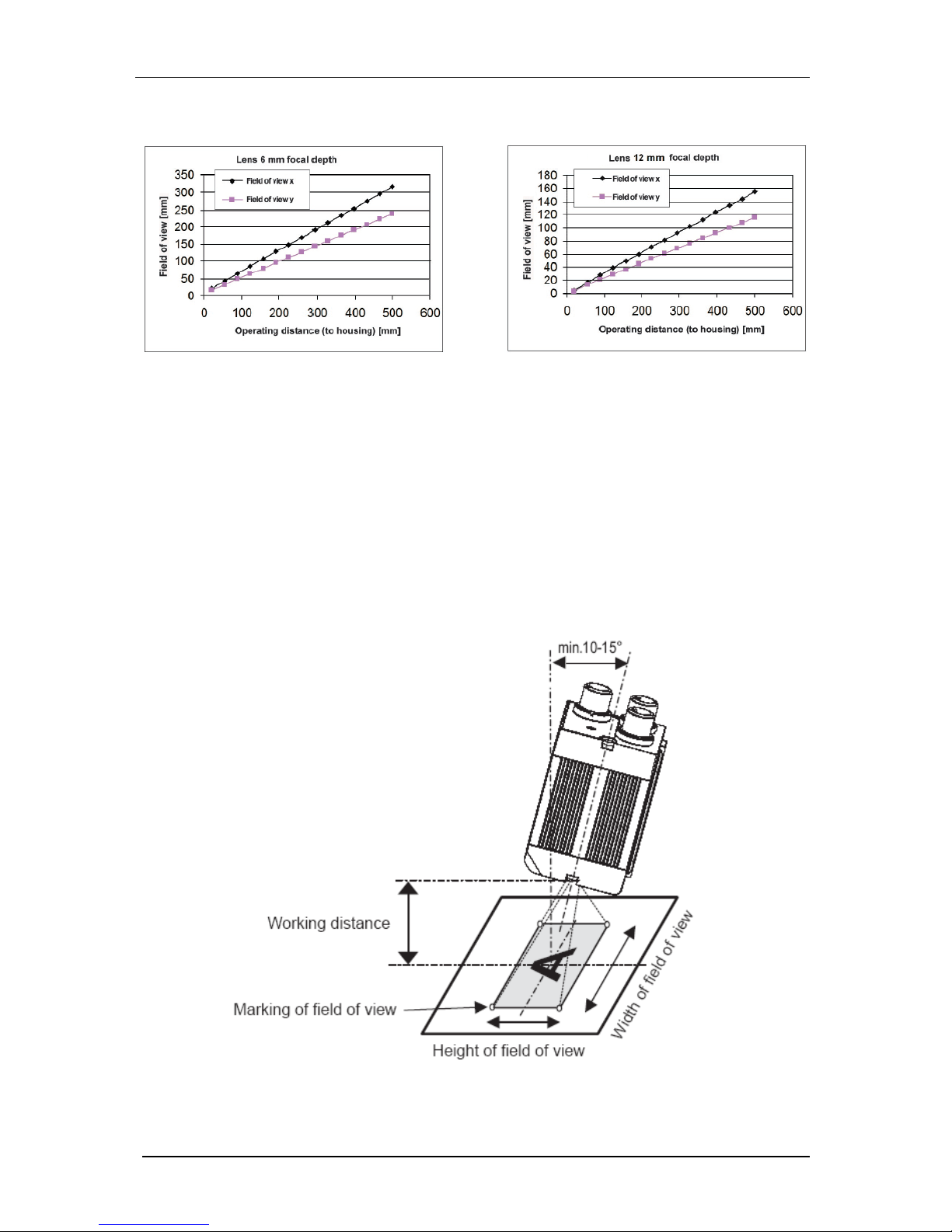
2.2 Lenses
The VisiCube camera is available with 12mm micro lenses of 2 different focal Length, f = 6mm and f =
12mm. The lens can be easily focused by turning the “Focus” screw at the back of the camera.
The minimum working distance for both lenses is 20mm.
Focusing can be done using the “imgX” image transfer programs and the ATX cl ient (available for
download from the “Customer Area -> Software Utilities”.
© 1996-2007 Vision Components GmbH Ettlingen, Germany VisiCube.pdf
VisiCube Manual
3
The following Table shows the image size for both lenses depending on the working distance.
Min. field of view X * Y in mm: 18 * 14 Min. field of view X * Y in mm: 8 * 6
Both lenses are adjustable to infinity. Depth of focus approx. ± 5% of scan distance
2.3 LED Lighting
The inbuilt led light allows it to go without external lighting for most applications with working distances
of up to 100mm. 2 red LEDs have been added to the 6 high power white ones In order to compensate
for the typical blue domination in white LED light.
In order to avoid light reflections it is recommended to mount the camera with a slight deviation angle
form the vertical direction as shown below.
Programming of the LED light is detailed in section 6.
© 1996-2007 Vision Components GmbH Ettlingen, Germany VisiCube.pdf

VisiCube Manual
4
3 Technical Specifications VisiCube Smart Camera
Component / Feature Specification
CCD Sensor: 1/4" SONY ICX098BL
eff. no. of pixels: 640(H) x 480(V)
Pixel size: 5.6(H) x 5.6(V) µm
Chip size: 4.6(H) x 3.97(V) mm
High-speed shutter: 36.21, 98.6, 161 microseconds, increasing with steps of 62.4
microseconds (full-frame shutter)
Low-speed shutter: up to 2 sec. adjustable integration time
Integration: full-frame
Picture taking: program-controlled, trigger controlled (interrupt); full-frame / 32 frames
per second, external high speed trigger
Clamping: zero offset digital clamping
A/D conversion: 12.5 MHz / 10 bit, only the 8 most significant bits used for grey values
Input LUT none
Image Display Via 100 Mbit Ethernet onto PC
Processor: Texas Instruments TMS320C64XX signal processor 400 MHz,
3200MIPS
RAM: 32 Mbytes SDRAM (synchronous dynamic RAM)
Memory capacity: Up to 100 full-size images in format 640x480
Flash EPROM: 4 Mbytes flash EPROM (nonvolatile memory) for programs and data, in-
system programmable, 3 MB available to user
MMC: Not available
Process interface: 2 inputs / 4 outputs, outputs 4x200 mA
Illumination Controller: LEDs on during exposure, user controlled, boost mode, see section 6.5
Ethernet interface: 100 Mbit Full Duplex, changeable to 10 Mbit, changeable to half duplex
CE certification: CE Certification tested and approved
Storage Conditions Temperature: -20 to 60 deg C, Max. humidity: 90%, non condensing.
Operating Conditions Temperature: 0… +50 deg C (ambient temperature, if LEDs exposure
controlled and not in boost mode), Max. humidity: 80%, non condensing.
Power Supply 24V ± 10%, absolute maximum 18V – 30V
Power Consumption ≈2.4W (current drawn from PLC outputs additional)
1
From CPLD file version 4 – check with shell command “ver”.
© 1996-2007 Vision Components GmbH Ettlingen, Germany VisiCube.pdf

VisiCube Manual
5
4 VisiCube Interfaces
4.1 Power Suppl y / SPS IO Interface and Trigger interface
PIN Color Use
1 White IN1 (external trigger)
2 Brown +UB(24 V DC)
3 Green OUT3 (pattern good/bad)
display LED = Q1
4 Yellow OUT2
5 Grey IN2
6 Pink OUT1 (Trigge r of external illumination)
7 Blue GND
8 Red OUT4 (position good / bad)
© 1996-2007 Vision Components GmbH Ettlingen, Germany VisiCube.pdf

VisiCube Manual
6
Electrical data Power Supply / SPS IO and Trigger interface
Operating voltage UB 24 V DC ± 10% (absolute maximum 18 - 30 V)
Residual ripple < 5 Vss
Current consumption (no
I/O
max. 200 mA
Inputs IN1 / IN2
high 10 V
.. +U
B
(+10%), low 0 ... 3 V
Input resistance
> 20
kOhm
Trigger input rising edge, 10 V ... UB
Outputs OUT1 - 4 PNP (closer, pull up MOSFET)
Output current (per
output)
200 mA (>> max. 9,6 W)
Maximum output current
(per output)
1,5 A in case of short circuit
Short-circuit protection
(all outputs)
yes
Protection against inverse
connection
yes
Interfaces Ethernet (LAN) RS422
Protection system 2
Readiness delay approx. 6 sec. after power on
4.2 LAN / Ethernet Interface
PIN
(M12)
Color PIN
(RJ45)
Use
1 White/blue 5
2 White /blue 7
3 Brown 8
4 Orange 2 TxD5 White/green 3 RxD+
6 White/orange 1 TxD+
7 Blue 4
8 Green 6 RxD-
Pin Assignment and cable core colors
The IP Address adjustment works equivalent as with all other current VC Smart Camera models.
Refer to the “Getting Started VC…” Documentation for details.
© 1996-2007 Vision Components GmbH Ettlingen, Germany VisiCube.pdf

VisiCube Manual
7
4.3 Data / RS422 Interface
PIN Color Use
1 White RxD2 Brown RxD+
3 Green TxD+
4 Yellow TxD-
5
GND
© 1996-2007 Vision Components GmbH Ettlingen, Germany VisiCube.pdf

VisiCube Manual
8
5 Order Numbers of VisiCube and Accessories
Description
VK.- Number
VisiCube with f = 6mm Micro lens VK000327
VisiCube with f = 12mm Micro lens VK000328
Description Type VK.- Number
Mounting clamp, dovetail FA45 MK 45 VK000320
Mounting angle FA45 MA 45 VK000322
Mounting rod 20 cm FA45 MST 45-20 VK000325
Mounting rod 30 cm FA45 MST 45-30 VK000340
Mounting rod 40 cm FA45 MST 45-40 VK000339
Mounting hinge FA45 MG 45 VK000321
Mounting plate FA45 MP 45 VK000323
Mounting link FA45 MZ 45 VK000324
Connection cable, 2 m, straight, shielded C L8FSK-2m-G-PUR VK000318
Connection cable, 5 m, straight, shielded C L8FSK-5m-G-PUR VK000338
Connection cable, 2 m, 90°, shielded C L8FSK-2m-W-PUR VK000337
Connection cable, 5 m, 90°, shielded C L8FSK-5m-W-PUR VK000336
Ethernet cable, 3 m M12, 8pin./RJ45,
shielded
CI L8FSK/RJ45S-3mGG-PVC-G
VK000319
Interface cable 3 m, straight CI L5FK-3m-G-PUR VK000334
Interface cable 3 m, 90° CI L5FK-3m-W-PUR VK000335
© 1996-2007 Vision Components GmbH Ettlingen, Germany VisiCube.pdf

VisiCube Manual
9
6 Programming of special VisiCube Features
6.1 Using PLC Inputs and Outputs
Using the PLC IOs works like with all other VC Smart cameras, so the demo program “port.c” can be
used as a reference.
Differences to other VC Smart Cameras:
- The naming convention is slightly different for the VisiCube, with the 4 outputs ranging from
OUT1 to OUT 4 (so OUT0 in the port demo program corresponds to OUT1 in 4.1 (pin
allocation of VisiCube Power Supply / IO interface).
- Like the VCSBC40XX, the VisiCube has only 2 digital inputs (IN1 and IN2). The registers for
IN3 and IN4 are set to high.
Check Status on PLC inputs:
print("INP0=%d ",inPLC()&0x01); // query status of Input 1
print("INP1=%d ",inPLC()&0x02); // query status of Input 2
Set and Re-Set PLC outputs:
setPLC0(); resPLC0(); //set and re-set Output 1
setPLC1(); resPLC1(); //set and re-set Output 2
setPLC2(); resPLC2(); //set and re-set Output 3
setPLC3(); resPLC3(); //set and re-set Output 4
6.2 Capturing Images with a Hardw are Trigger Signal
The VisiCube does not incorporate a dedicated HW trigger interface, so images have to be triggered
using one of the digital PLC inputs IN1 or IN2.
while ( wait(PLC_INT, 100) != 1); // wait for change on PLC inputs while freeing CPU time
If (inPLC()&0x01) ==1) ; //check if status of PLC input 1 has changed
tpict(); // take image
Refer to Appendix B: Using the PLC_INT event.
© 1996-2007 Vision Components GmbH Ettlingen, Germany VisiCube.pdf

VisiCube Manual
10
6.3 Using the RS422 Data Interface of the VisiCube
Demo Program t132.c – order the corresponding “Interface Cable” for instance VK000334, interface
cable straight, 3m (see section 5).
#include <register.h>
#include <vcrt.h>
#include <sysvar.h>
main()
{
FILE *tty;
//unsigned xbaud=115200;
unsigned xbaud=9600;
char c=0;
print("TEST RS422 serial I/O\n");
tty = fopen("ittya:", (void *)0); /* open RS422 */
io_ioctl(tty,IO_IOCTL_SERIAL_SET_BAUD,&xbaud);
write(tty,"abcdefg",7);
rs232rcv();
while(c != 0x1b)
{
c=rs232rcv();
// c=io_fgetc(tty);
io_fputc(c, tty);
c=io_fgetc(tty);
rs232snd(c);
}
fclose(tty); /* close RS422 */
}
6.4 Using the Status LEDs
The following macro sets the LED register:
LED_OUT(x)
3 2 1 0 Bits
Q2 Q1 Err. Pwr Name
The bit logic is inverted, so x = 0 turns all LEDs on, x = 15 switches all LEDs off.
Use an additional variable (for instance “private sysvar” to store the actual LED status since this
register is write only!
© 1996-2007 Vision Components GmbH Ettlingen, Germany VisiCube.pdf

VisiCube Manual
11
6.5 Using the LED Lighting
Per default the illumination LED’s are on during exposure (at low level – not “boost level”).
The following macros turn the LEDs off during exposure:
ILLU_USR(); // turning the LEDs into “User mode”
ILLU_POS(); // turning the LEDs on – program controlled
ILLU_NEG(); // turning the LEDs on – program controlled
The following macros then turn the LEDs on again during exposure:
ILLU_EXP(); // turning the LED Illumination into “Exposure Mode”
ILLU_POS(); // LEDs are on during exposure (ILLU_NEG() means LEDs are on when not exposing).
SET_BOOST(); // sets the Illumination LEDs to “boost level” (for example 233 mean grey value
instead of 171).
RES_BOOST(); // sets the Illumination LEDs back to “normal (default) level”.
!
Do not use the “boost” mode at high surrounding temperatures as can lead to overheating of
the camera.
Use the LED lighting only if required (i.e. during image acquisition) in order to extend their
lifetime.
© 1996-2007 Vision Components GmbH Ettlingen, Germany VisiCube.pdf

VisiCube Manual
12
7 Maintenance
7.1 Cleaning
- Clean the FA45 Object-Detection Sensor with a clean dry cloth.
- Do not use solvents or petrol.
- Do not use sharp objects.
- Do not scratch
.
7.2 Repair
- In case of a suspected hardware fault, please contact at first your distributor/ point of
purchase for assistance.
- If the problem cannot be solved locally, please use the following link to fill in the RMA form
on the website under “Support + Download”:
Support + Download
Send Camera for
Repair
- Please provide a detailed fault description and also let us know how you have tested this
fault in case the defect is not obvious.
- Carefully select if your country of residence is within or without the EU. This aut omatically
prints the correct shipment address on the RMA result sheet (important for customs
clearance).
- Login on to the VC website automatically fills in your address details.
- Clicking the “submit” button displays the RMA result sheet with the RMA number and a
summary of your fault description and details. This summary page is also sent to your
email address.
- Please print out this page and include it with your camera shipment.
- Please always use courier services (FedEx, UPS, DHL, etc) for shipping, since we are
unable to get customs clearance if cameras are sent by normal mail services.
!
Repair / Hardware Upgrade Costs:
- Warranty repairs are free of charge if not due to camera misuse.
- After expiry of the warranty period most repairs or upgrades are done at a small flat fee.
Check with your distributor for details.
Hardware or SW fault?
- To save time and costs, please only send cameras with definite hardware faults.
- Please ensure the failure is not due to:
© 1996-2007 Vision Components GmbH Ettlingen, Germany VisiCube.pdf

VisiCube Manual
13
- A SW problem (for instance most suspected Flash errors are SW problems /
Communication errors are often due to wrong IP settings, etc.)
- Hardware failure of accessories (cables, connected sensors, etc.)
Please check the VC documentation and the Knowledge Base / FAQ for possible SW errors.
If in doubt please contact
Vision Components Support for assistance prior to shipping!
Vision Components can only accept products for repair that have been directly purchased form
us or one of our authorized distributors.
Please contact your point of sale, if you have purchased a VC Smart Camera from another
vendor!
© 1996-2007 Vision Components GmbH Ettlingen, Germany VisiCube.pdf

VisiCube Manual
A
Appendix A: Dimensional Drawings of VisiCube
Mounting Brackets:
© 1996-2007 Vision Components GmbH Ettlingen, Germany VisiCube.pdf

VisiCube Manual
B
Appendix B: Using the PLC_INT event
//////////////////////////////////////////////////////////////////////
// 6. Using PLC_INT event for detecting status change at PLC inputs //
//////////////////////////////////////////////////////////////////////
print("\nPress any key to start waiting for PLC event (timeout 5s) \n Press 'q' to stop \n");
getchar();
// waiting for the PLC event does not require processing time (as polling of inputs does) parallel processes can execute
// the PLC_INT reacts to changes (transition from low to high or high to low) at any PLC
inputs
do
{
if (kbhit())
{
key = rs232rcv();
}
do
{
x = wait(PLC_INT, 5000); // waits until next event "PLC Event" occurs, timeout 5s
} while((x!=1)&&(x!=-1)&&(x!=2)); // wait returns 2 and does not wait for
the next event, if the event has occurred before wait was called
print("INP0=%d ",inPLC()&0x01);
print("INP1=%d ",inPLC()&0x02);
switch(x)
{
case 1:
print("PLC_INT event occurred\n");
break;
case 2:
print("PLC_INT event event has occurred before wait was called\n");
break;
case -1:
print("PLC_INT event has timed out\n");
break;
default:
print("Return value wait(EXP_READY,x) = %d \n", x);
}
}while(key != 'q');
}
/*******************************************************************/
© 1996-2007 Vision Components GmbH Ettlingen, Germany VisiCube.pdf

VisiCube Manual
C
© 1996-2007 Vision Components GmbH Ettlingen, Germany VisiCube.pdf

VisiCube Manual
D
Visit the Vision Components site www.vision-components.com for further information and
documentation and software downloads:
Web Site Menu Links Content
Contact
Distributor list / Enquiry forms
Home
Latest News from VC
Our Company
VC Company Information
News and Events
Trade Show dates
VC Publications
Sign in for free VC Seminars
VC Network
Description of Partner Companies
Application Overview
3
rd
Party Hard- and SW Products for VC Smart
Cameras
Products
VC Smart Camera Overview
Product Overview:
VC44XX High End Camera Series
VC40XX Standard Camera Series
VC4016 / 18 Entry Level Cameras
VC4002L Line Scan Camera
VCSBC Single Board Cameras
VC20XX Smart Cameras
VCSBC Board Cameras
VCM + Viscube Camera Sensors
VC Smart Camera Software
VC Software Development Kit Ti: VCRT Operating System
VCLIB Image Processing Library
VC Special Libraries: M200 Data Matrix Code Reader
VCOCR Text Recognition Library
Color Lib
Support:
Support News (User Registration required) Tech News – new SW and Documentation
Knowledge Base / FAQ (User Registration
required)
Searchable FAQ Database with programming
Examples and Demo Code
Download Area Download of:
Public Download Area
(free Access)
- Product Brochures
- Camera Manuals
Registered User Area
(User Registration required)
-
Getting Started
- Programming Manuals
- Tr aining Manuals and Demo Code
Customer Download Area
(User- and SW License
Registration required)
- Software Updates
- Demo Code
RMA Number Form Form for Allocation of Repair Numbers.
© 1996-2007 Vision Components GmbH Ettlingen, Germany VisiCube.pdf
 Loading...