

1
TC-MATRIX_manual_en.doc
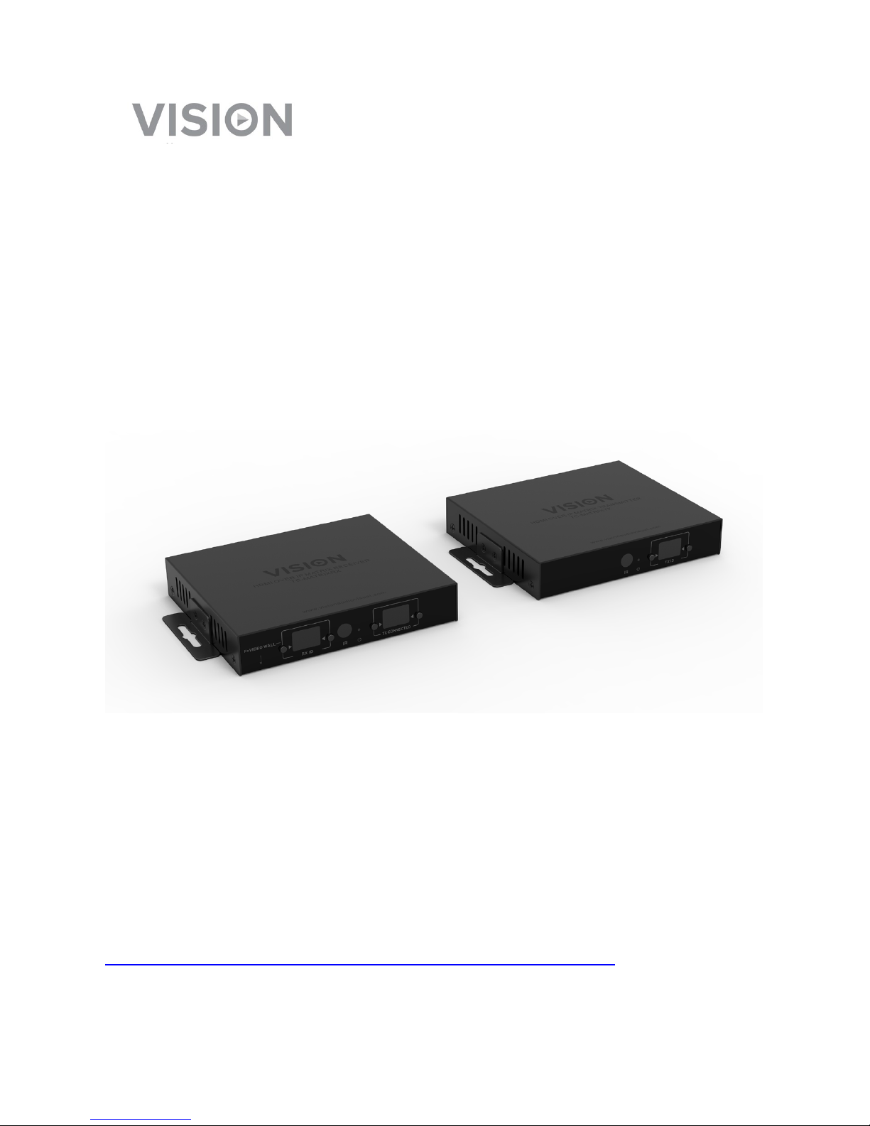
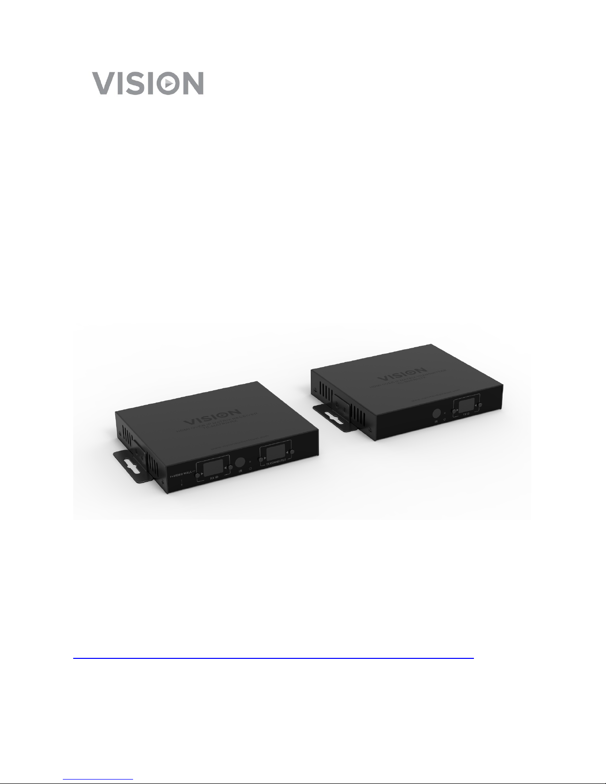
TECHCONNECT TC-MATRIX
OWNERS MANUAL
www.visionaudiovisual.com/techconnect/tc-matrix/

2
TC-MATRIX_manual_en.doc
DECLARATION OF CONFORMITY
Where applicable Vision products are certified and comply with all known local regulations to a
‘CB Certification’ standard. Vision commits to ensure all products are fully compliant with all
applicable certification standards for sale in the EU and other participating countries.
The product described in this owner manual is in compliance with RoHS (EU directive
2002/95/EC), and WEEE (EU directive 2002/96/EC) standards. This product should be returned
to the place of purchase at the end of its useful life for recycling.
WARNINGS
CAUTION: TO REDUCE THE RISK OF ELECTRIC SHOCK DO NOT REMOVE COVER (OR
BACK). NO USER-SERVICEABLE PARTS INSIDE. REFER SERVICING TO QUALIFIED
SERVICE PERSONNEL.
The lightning flash with arrowhead symbol, within an equilateral triangle, is intended to alert the
user to the presence of uninsulated “dangerous voltage” within the product’s enclosure that may be
of sufficient magnitude to constitute a risk of electric shock to persons.
The exclamation point within an equilateral triangle, is intended to alert the user to the presence of
important operating and maintenance (servicing) instructions in the literature accompanying the
appliance.
WARNING: TO REDUCE THE RISK OF FIRE OR ELECTRIC SHOCK, DO NOT EXPOSE
THIS APPLIANCE TO RAIN OR MOISTURE.
All products are designed and imported into the EU by ‘Vision’ who is wholly owned by ‘Azlan
Logistics Ltd.’, Registered in England Nr. 04625566 at Lion House, 4 Pioneer Business Park,
Clifton Moor, York, YO30 4GH. WEEE Registration: GD0046SY
DECLARATION OF ORIGIN
All Vision products are made in the People’s Republic of China (PRC).

3
TC-MATRIX_manual_en.doc
USE ONLY DOMESTIC AC OUTLETS
Connecting the unit to an outlet supplying a higher voltage may create a fire hazard.
HANDLE THE POWER CORD WITH CARE
Do not disconnect the plug from the AC outlet by pulling the cord; always pull the plug itself.
Pulling the cord may damage it. If you do not intend to use your unit for any considerable
length of time, unplug the unit. Do not place furniture or other heavy objects on the cord, and
try to avoid dropping heavy objects on it. Do not tie a knot in the power cord. Not only could
the cord be damaged, but a short circuit could also be caused with a consequent fire hazard.
PLACE OF INSTALLATION
Avoid installing this product under the following conditions:
• Moist or humid places
• Places exposed to direct sunlight or close to heating equipment
• Extremely cold locations
• Places subject to excessive vibration or dust
• Poorly ventilated places
Do not expose this product to dripping or splashing. DO NOT PLACE OBJECTS FILLED WITH
LIQUIDS ON OR NEAR THIS PRODUCT!
MOVING THE UNIT
Before moving the unit, be sure to pull out the power cord from the AC outlet and disconnect
the interconnection cords with other units.
WARNING SIGNS
If you detect an abnormal smell or smoke, turn this product off immediately and unplug the
power cord. Contact your reseller or Vision.
PACKAGING
Save all packing material. It is essential for shipping in the event the unit ever needs repair.
IF ORIGINAL PACKAGING IS NOT USED TO RETURN THE UNIT TO THE SERVICE CENTRE,
DAMAGE IN TRANSIT WILL NOT BE COVERED BY WARRANTY.

4
TC-MATRIX_manual_en.doc
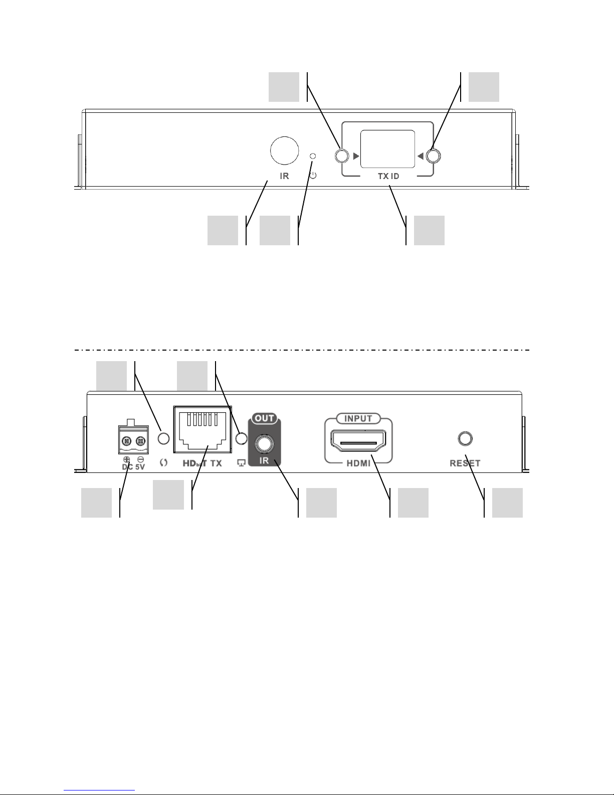
TRANSMITTER
1. IR receiver (to switch Matrix channel, not for IR passthrough)
2. Standby indicator
3. Channel adjust button
4. Channel display (each Tx in system must be set to different channel)
5. Channel adjust button
1. 5V 3A Power input (note device cannot run on PoE)
2. Data transmission indicator
a. Slow flashing; establishing connection
b. Fast flashing; successfully connected and transmitting data
3. CAT5e/6 Output
4. Connection indicator; if no light then not connected to Rx
5. IR blaster minijack socket (plug IR blaster in here)
6. HDMI Input
7. Reset/restart button
1
2
3 1 5 4 2 3 4 5 6
7
5
TC-MATRIX_manual_en.doc
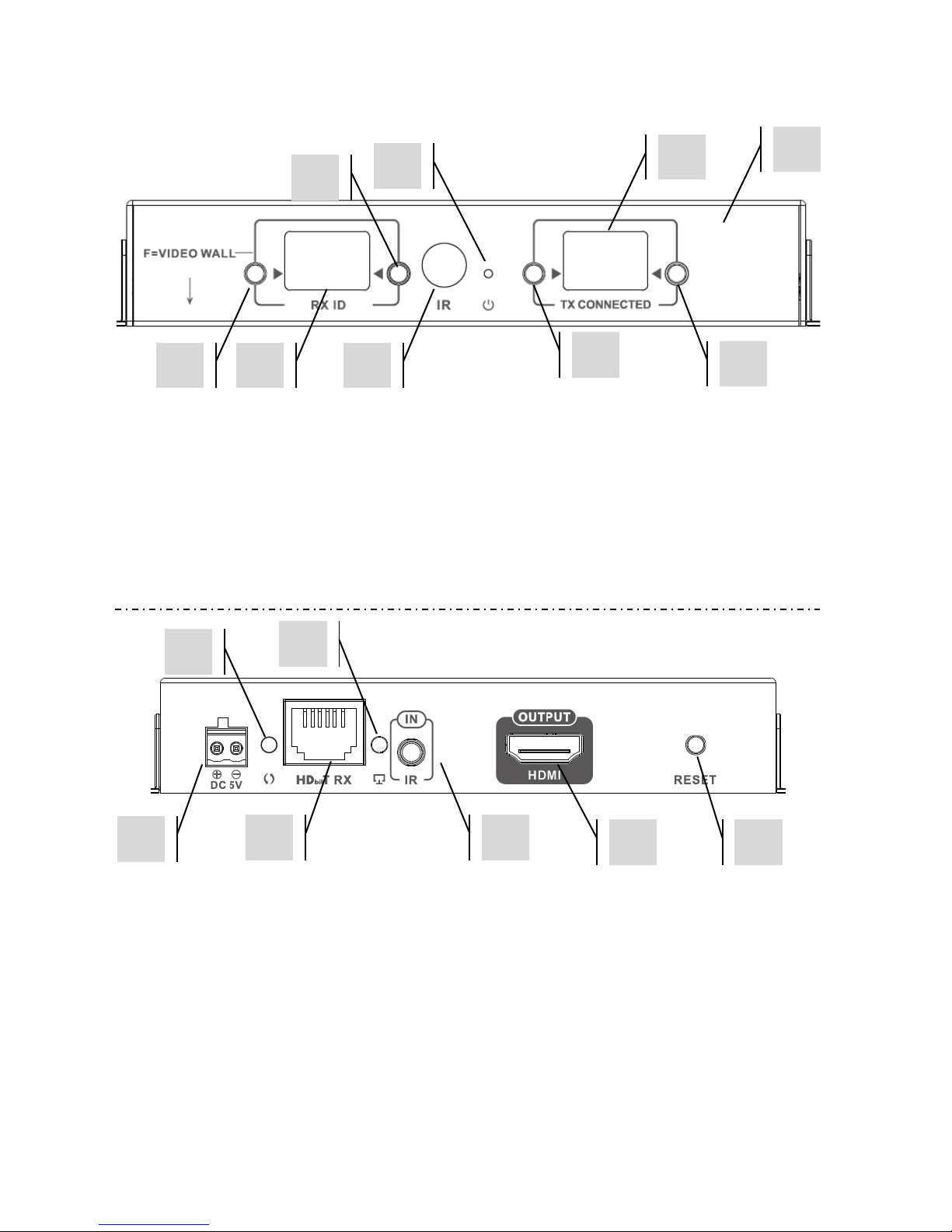
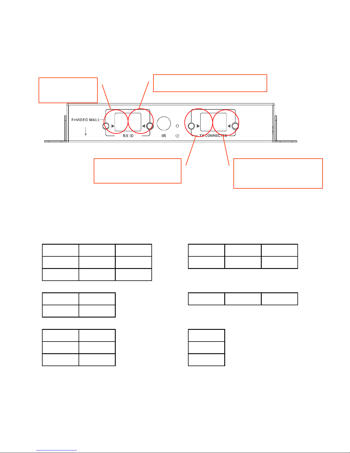
RECEIVER
1. Channel adjust button
2. Channel display (each Rx in system must be set to different channel)
3. Channel adjust button
4. IR receiver (to switch Matrix channel, not for IR passthrough)
5. Standby indicator
6. TX Channel adjust button
7. TX Channel display (determines which source this Rx will display)
8. TX Channel adjust button
1. 5V 3A Power input (note device cannot run on PoE)
2. Data transmission indicator
a. Slow flashing; establishing connection
b. Fast flashing; successfully connected and transmitting data
3. CAT5e/6 Input
4. Connection indicator; if no light then not connected to Tx
5. IR Receiver minijack socket (plug IR receiver in here)
6. HDMI Output
7. Reset/restart button
1 2 5 8 7 6 3 4 9 1 2
3 4 5 6 7

6
TC-MATRIX_manual_en.doc
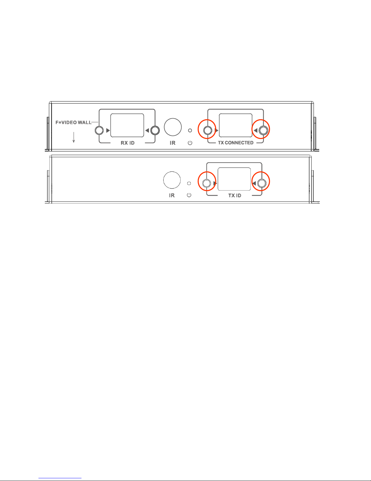
FACTORY RESET
1/ Hold the two buttons circled at the same time until 00 is displayed
2/ Disconnect power
3/ Wait 3 seconds
4/ Reconnect power
7
TC-MATRIX_manual_en.doc
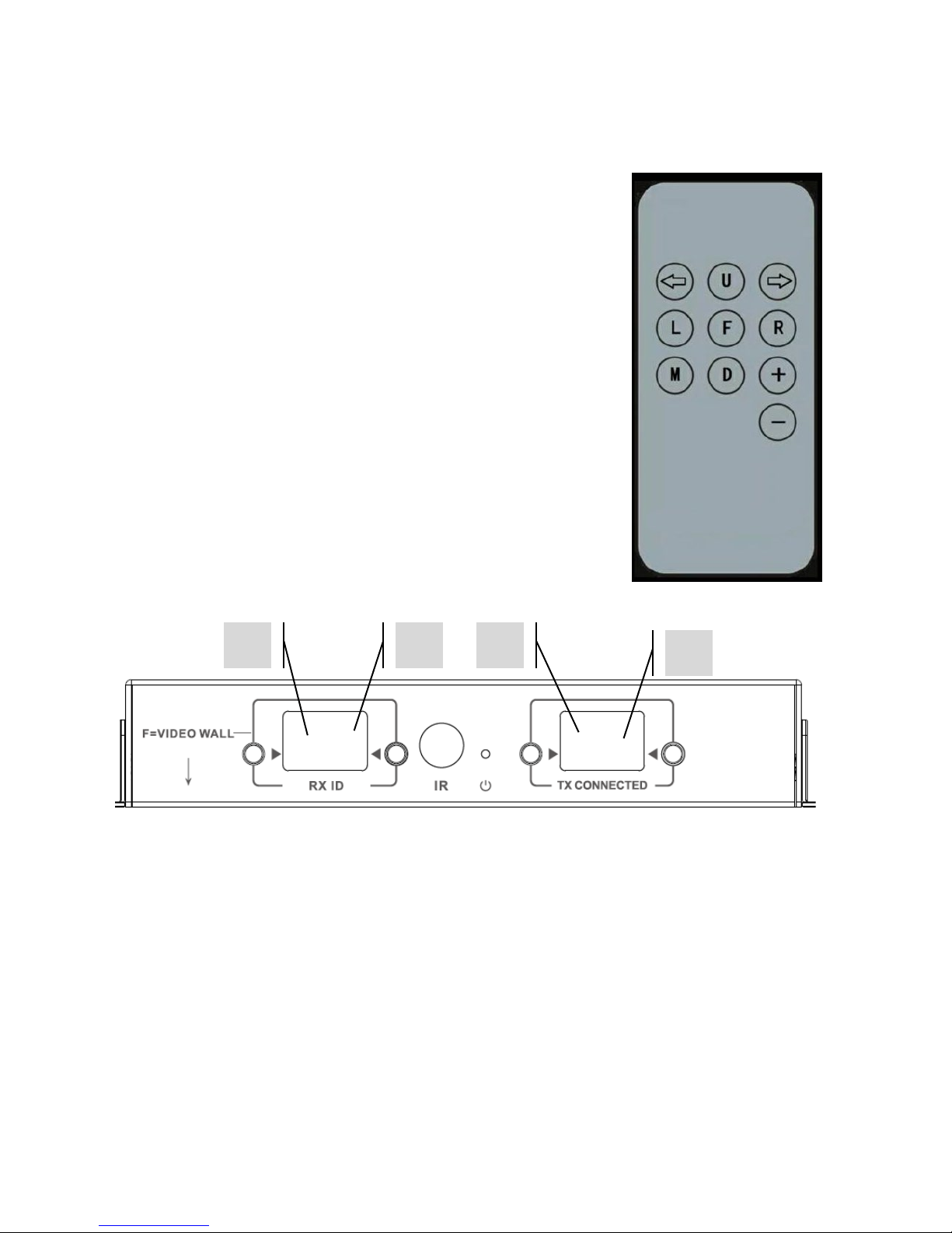
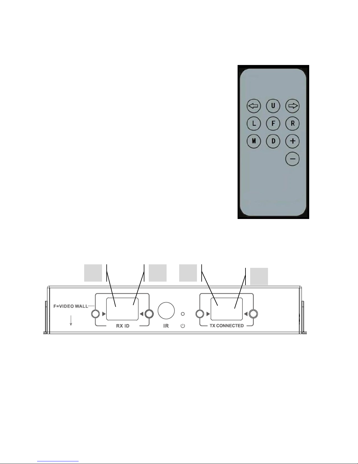
REMOTE CONTROL
M – Normal Mode
F – Video Wall Mode
Video Wall related functions:
L – Left
R – Right
U – Up
D – Down
(See Video Wall section for more information)
Left Arrow / Right Arrow
Selects LCD to adjust. LCD will start flashing:
+ / -
Once LCD is flashing, use these buttons to adjust up or down.
1 2 3
4

8
TC-MATRIX_manual_en.doc
SETUP – POINT TO POINT
It is not necessary to run the signal through a network switch. To use as an HDMI extender:
1. CONNECT TX TO RX Use a CAT6 cable to link a Tx directly to an Rx. The CAT6 cable must
be wired using normal IEEE-568B standard. It can be UTP or STP. Maximum length: 120
metres (394ft).
2. SET “TX CONNECTED” CHANNEL ON RX to match the channel on the Tx.
9
TC-MATRIX_manual_en.doc
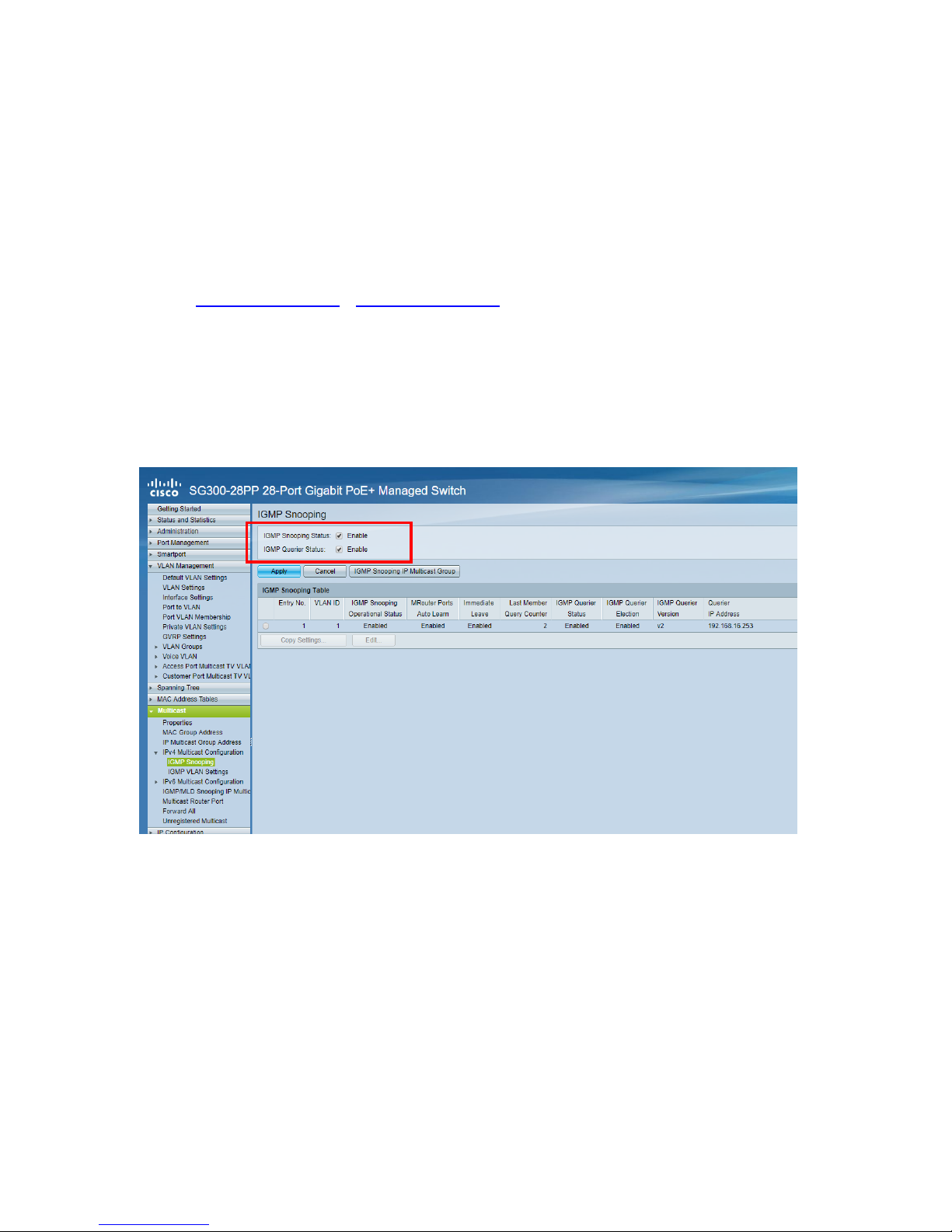
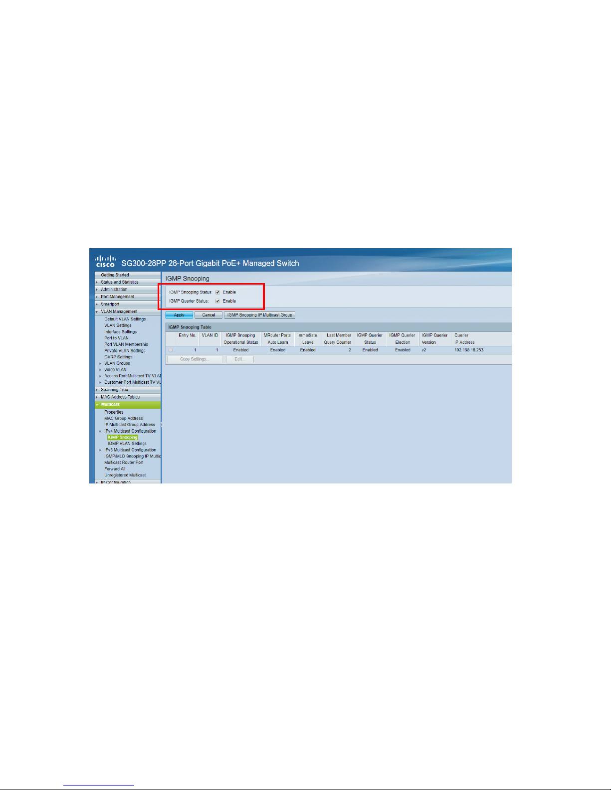
SETUP – OVER NETWORK
This product uses Multicasting which is what allows one transmitter to send to many receivers.
Multicasting changes the way a network behaves.
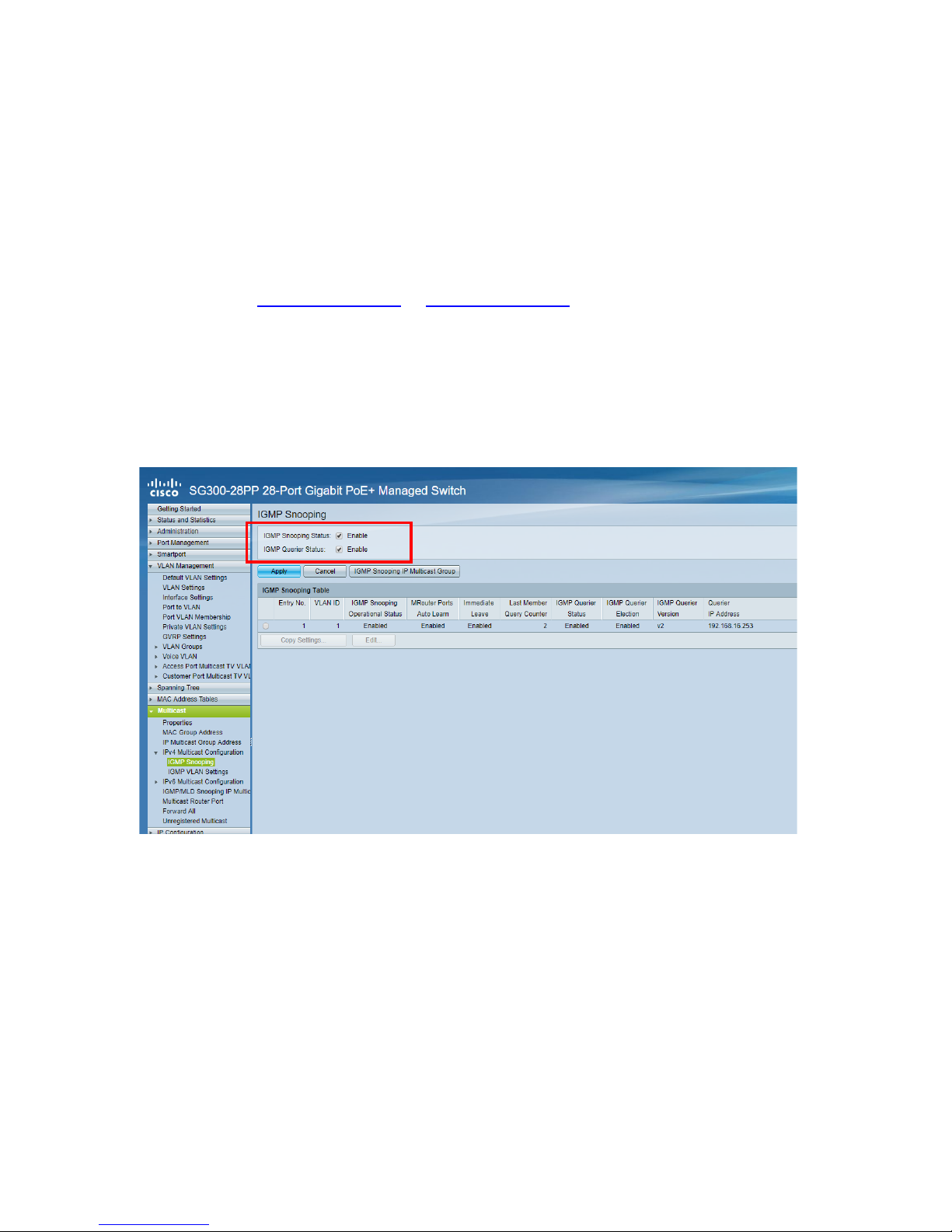
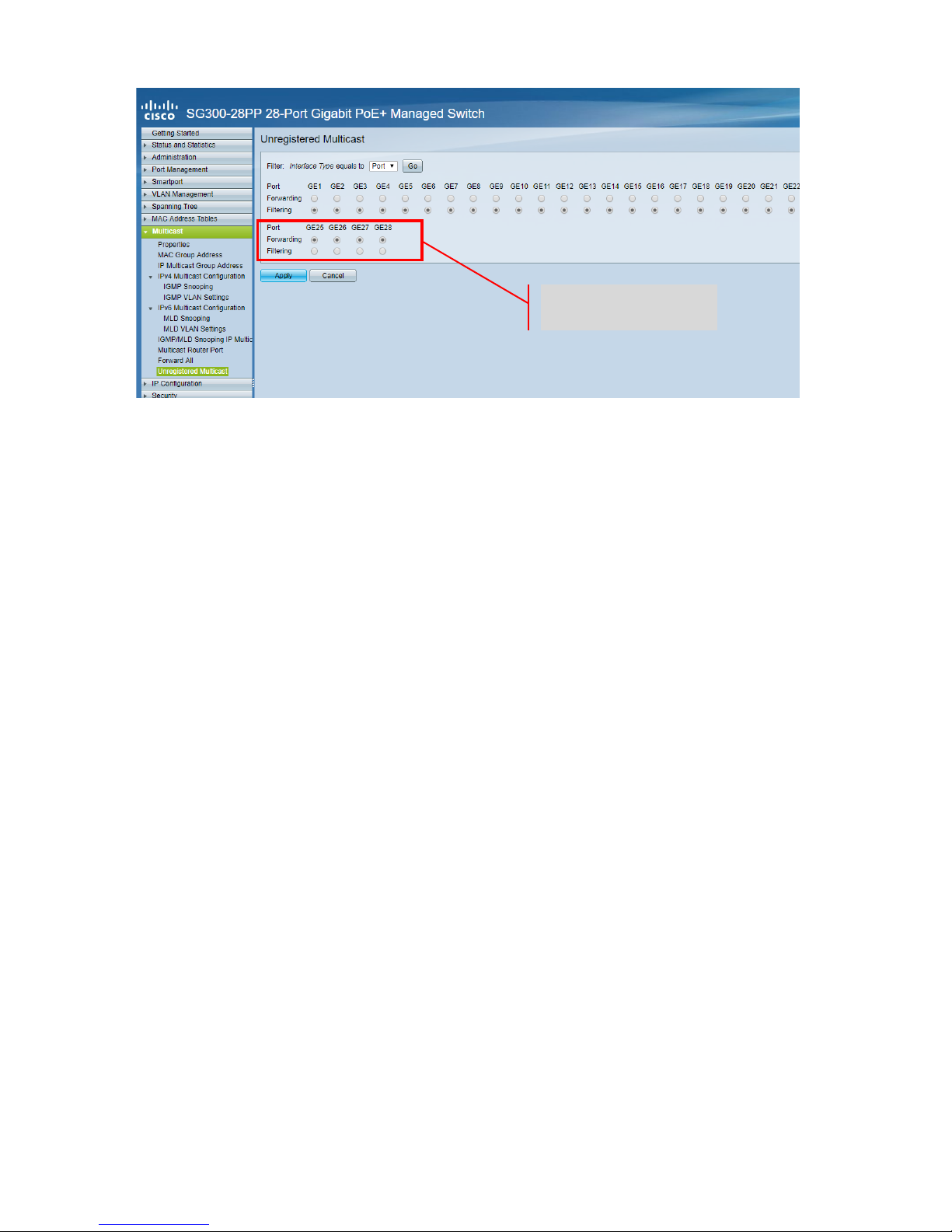
VERY IMPORTANT: To use this product IGMP snooping MUST be activated on the network
switch. This is what allows multicasting. IGMP snooping can only be activated on a “layer-3”
managed switch.
Consider Netgear’s M4300-28 (24 port) or M4300-52 (48 port)
as they are pre-configured for AV
Applications.
1. TURN IGMP SNOOPING ON You must use a managed switch. The network administrator
needs to go to the switch settings page in their browser and activate it.
10
TC-MATRIX_manual_en.doc
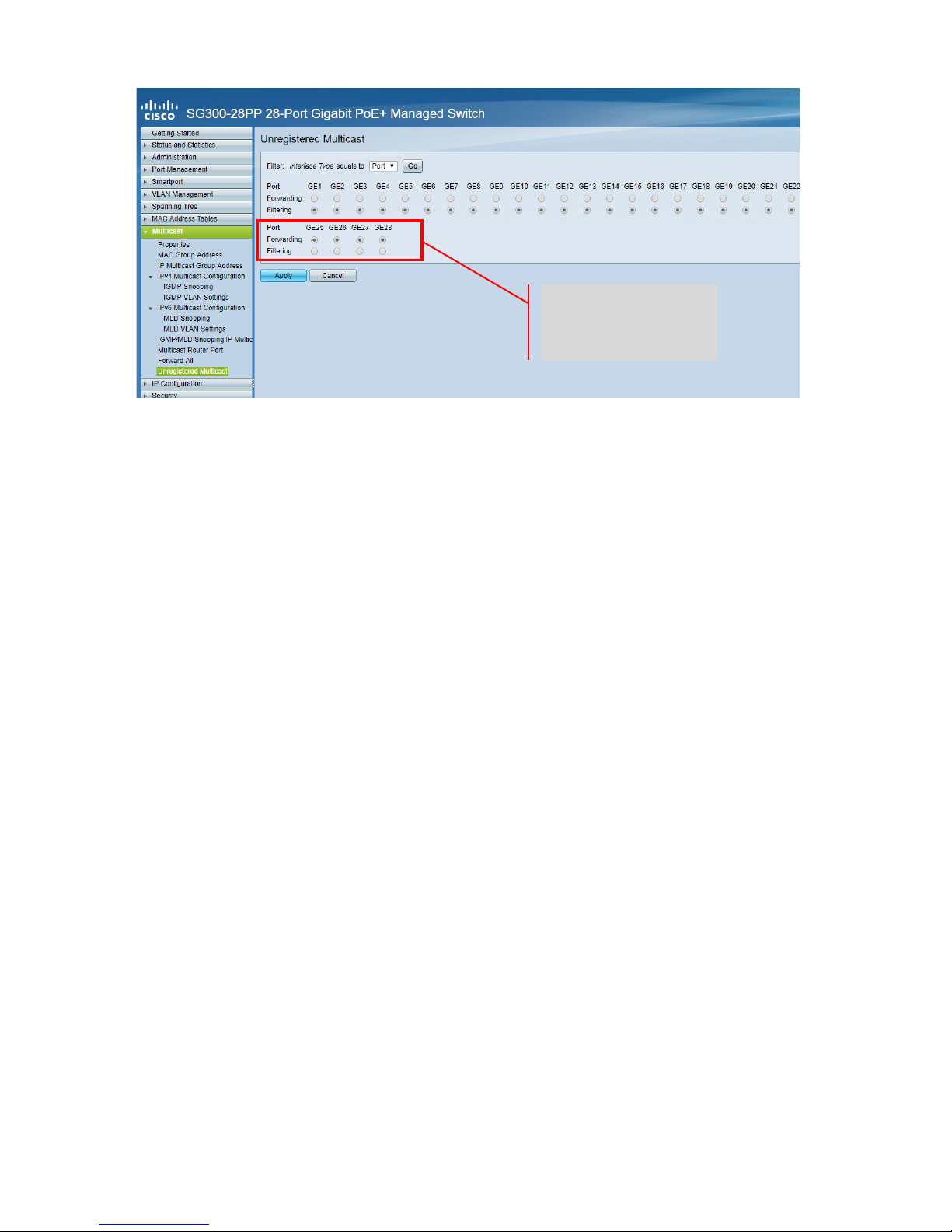
2. CONNECT ALL TX AND RX DEVICES TO NETWORK All devices must be on same subnet.
Microwave extenders may not have enough bandwidth to support this product which uses
up to 24Mbps transmitting 4K 60 Hz video
3. CONNECT SOURCES TO TX AND DISPLAYS TO RX One Tx for each source, one Rx for each
display. Uses proprietary encoding and cannot decode a stream from another product or
VLC.
4. SET CHANNEL ID ON ALL DEVICES
a. All Tx should be on different channels.
b. All Rx should be on different channels.
5. SET “TX CONNECTED” CHANNEL ON RECEIVERS The source connected to the Tx selected
will show on the display. Allow a few seconds for the HDCP handshake.
Set to Forwarding

11
TC-MATRIX_manual_en.doc
IR PASS THROUGH
The source remote control can be used at the display. It supports IR standards from 20-60 kHz.
This feature IS NOT Bi-directional; the signal is only carried from the receivers to the
transmitters.
1. CONNECT IR RECEIVER CABLE TO RX position the receiver diode near front of display.
2. CONNECT IR BLASTER CABLE TO TX position diode over the IR receiver window on the
source device.
12
TC-MATRIX_manual_en.doc
APP CONTROL
A free generic app called MATRIX CONTROL LITE is available from the Apple app store and
Google’s Play store. The app can be used for switching and renaming each end point.
1. INSTALL APP
2. CONNECT PHONE OR TABLET TO WIFI The wifi router must be on the same network as
the devices.
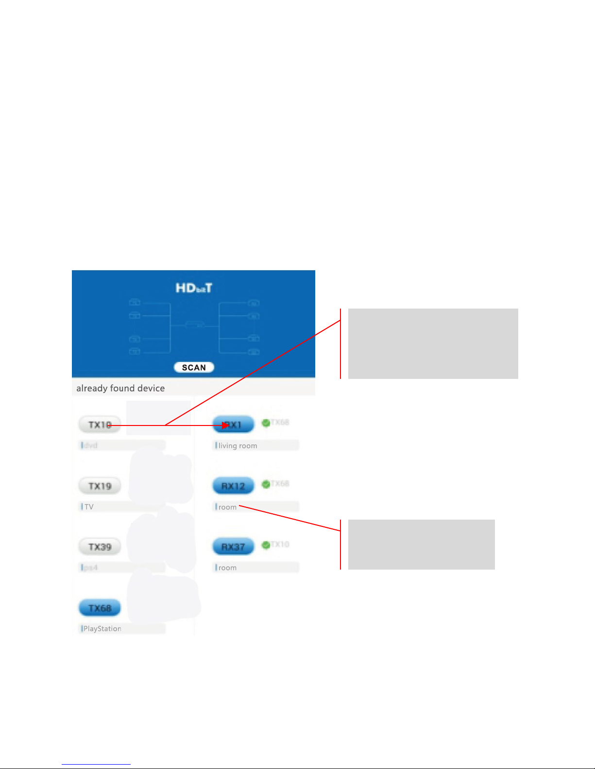
3. RUN APP then press SCAN to find Tx and Rx on network. They will automatically populate.
If they do not you are not on the same network.
To rename click here
Drag and Drop
to change “CONNECTED TX” of
RX1 to TX10
13
TC-MATRIX_manual_en.doc
CRESTRON OR AMX CONTROL
Download native Crestron and AMX drivers from
www.visionaudiovisual.com/techconnect/tc-
matrix/ to integrate into a larger system.
Note: Control is via IP. Check that firewalls and VPNs are disabled. The computer’s IP address
must be in the same range as the devices: 192.168.1.xxx
PC SOFTWARE
Software available from www.visionaudiovisual.com/techconnect/tc-matrix/
Allows switching like the app, and adds two advanced features:
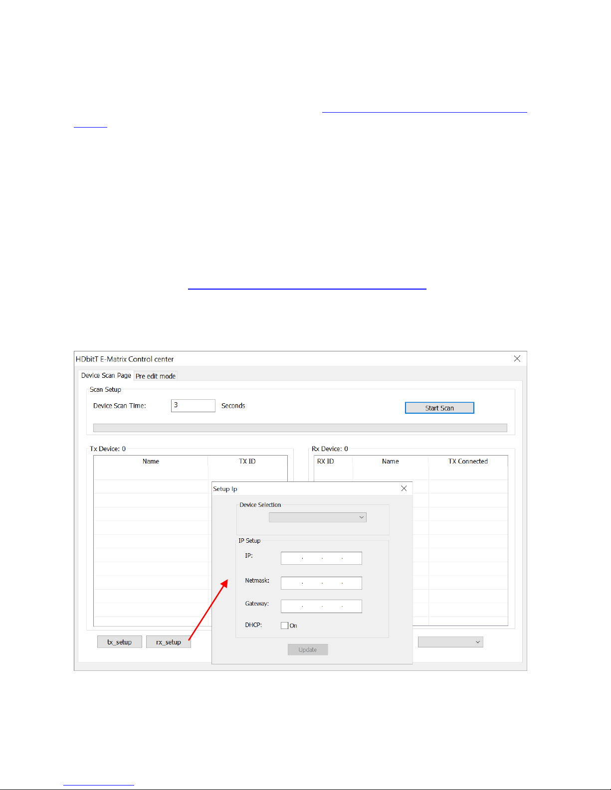
1. CHANGE DEVICE IP ADDRESSES For advanced management:
14
TC-MATRIX_manual_en.doc
2. CREATE “SCENES” OR “MODES” If uses want to switch more than one device at a time
they can use modes.
a. Create a scene and save it.
b. Create another scenario and save it.
c. Switch between the two.
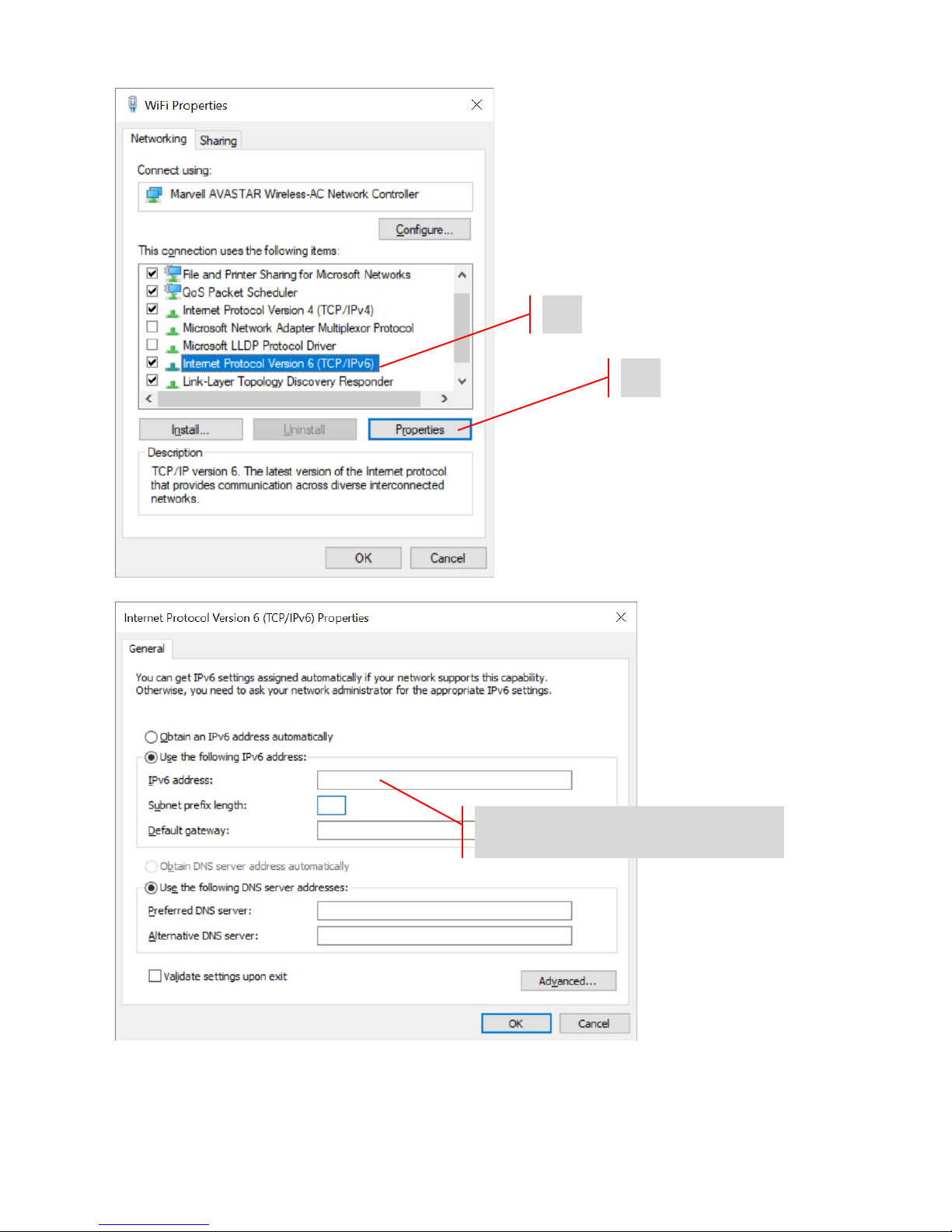
NOTE:
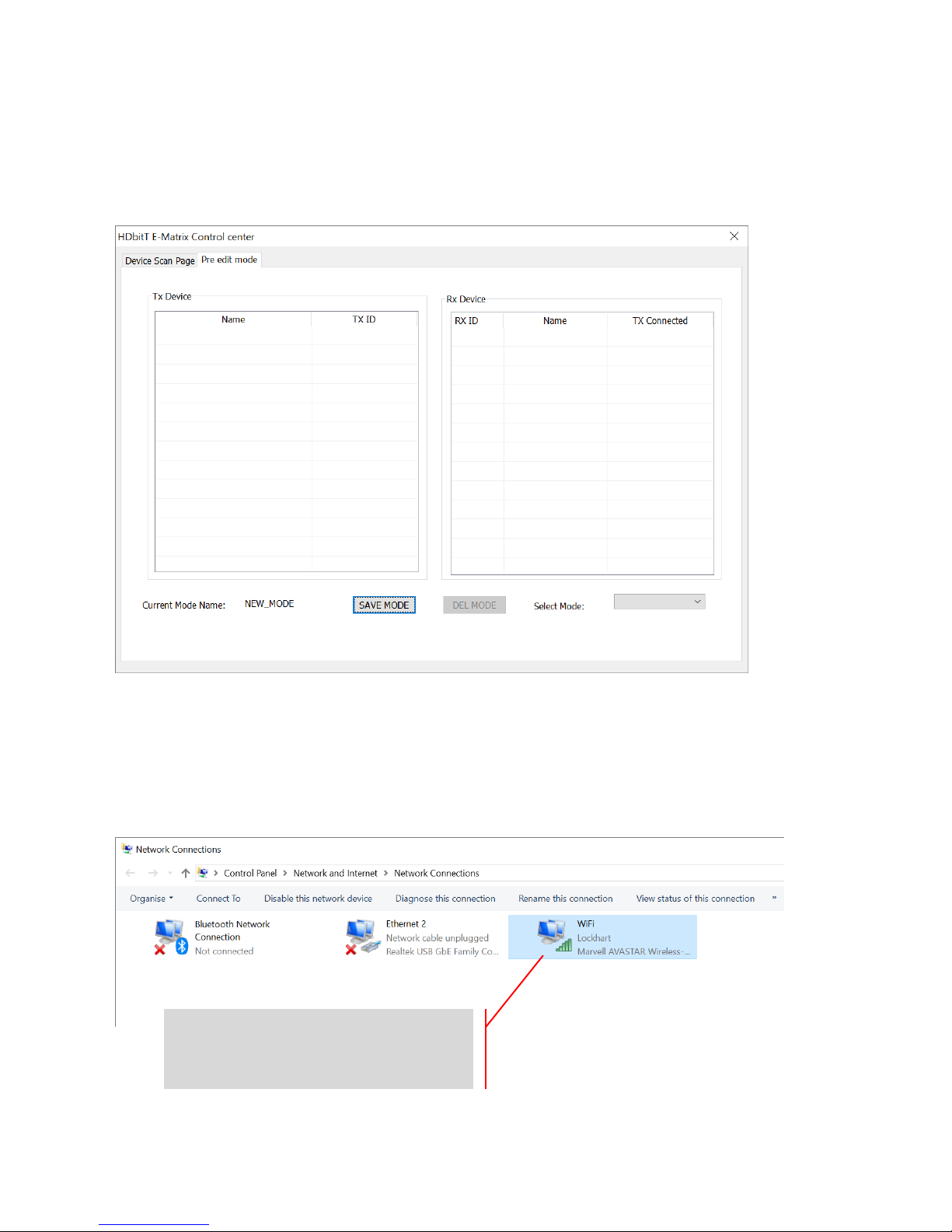
If devices cannot be found when you click SCAN check that firewalls and VPNs are
disabled. The computer’s IP address must be in the same range as the devices: 192.168.1.xxx
To change it in Windows 10 press the windows key and type: Network Connections
Right click and select Properties
15
TC-MATRIX_manual_en.doc
1
2
Enter 192.168.1.xxx here
16
TC-MATRIX_manual_en.doc
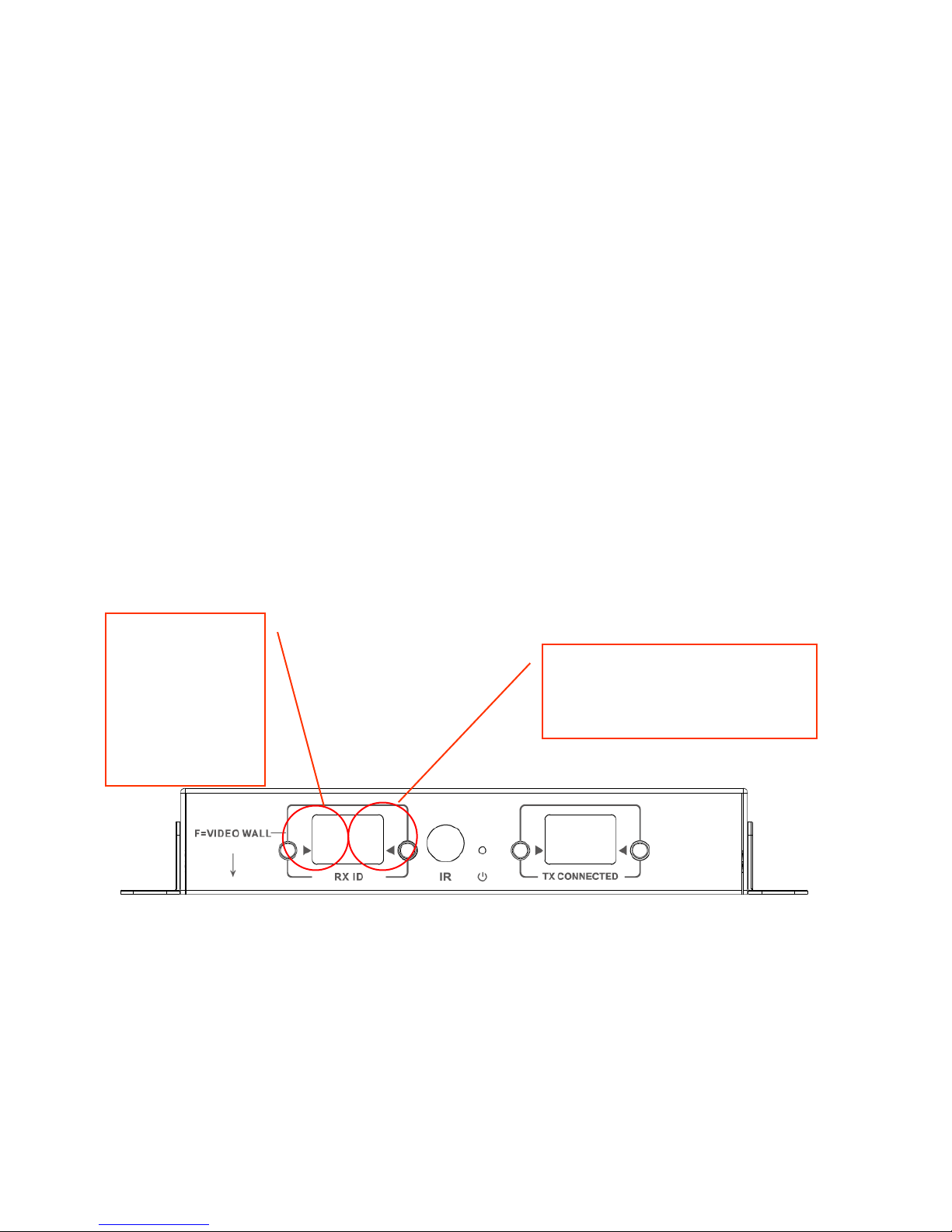
VIDEO WALL
Video wall configurations are pre-set. There is no bezel thickness adjustment.
Set channels on receivers:
Note: Video walls can only receive from up to 10 Tx.
Rx Channel Settings:
F1 1x F1 2x F1 3x
F4 1x F4 2x F4 3x
F1 4x F1 5x F1 6x
F4 4x F4 5x F4 6x
F1 7x F1 8x F1 9x
F2 1x F2 2x
F5 1x F5 2x F5 3x
F2 3x F2 4x
F3 1x F3 2x
F6 1x
F3 3x F3 4x
F6 2x
F3 5x F3 6x
F6 3x
1/ Set to F for
Video Wall
2/ Determines shape of wall
3/ Determines which
display this is attached to
4/ set which Tx is source
17
TC-MATRIX_manual_en.doc
Bezel Adjustment:
The RX ID buttons can be used to fine tune the image on the screen.
Pressing the left button cycles through:
0
1
2
3
4
5
6
7
8
9
F
L
R
U
D
The last four are used for Video Wall fine tuning:
Once adjustment done, select F again. All this can also be done on remote control.
1/ Press to cycle
through edges:
L Left
R Right
U Up
D Down
2/ Press to cycle through 10
steps of adjustment

18
TC-MATRIX_manual_en.doc
SPECIFICATIONS
PRODUCT DIMENSIONS: 164 x 108.5 x 23.6 mm / 6.46″ x 4.27″ x 0.93”
PACKAGED DIMENSIONS: 357 x 153.5 x 85 mm / 14″ x 6.04″ x 3.35”
PRODUCT WEIGHT: 330g / 0.73 lb
PACKAGED WEIGHT: 0.8kg / 1.76 lb
CONSTRUCTION MATERIAL: Metal
COLOUR: White
TECHNICAL DETAILS:
Input and Output TMDS Signal: 0.7-1.5 volts p-p
Input and Output DDC Signal: 5 volts p-p (TTL)
Maximum Video Format Supported: 4K
Output Video: HDMI 2.0 with HDCP 2.2
Output Audio: PCM
Compression: H.264
Input and Output HDMI Cable Length: 5m (16.4 ft) AWG 26
Operating Temperature Range: 0-50°C
Storage Temperature Range: -10-70°C
Operating Humidity Range: 0 to 90 % no condensation
Tx Power Consumption: 7 watts
Rx Power Consumption: 10 watts
CAT6 Maximum distance (if connected peer-to-peer directly): 120 m (394 ft)
IR Passback Bandwidth: 20-60 kHz
ESD protection: 1a Contact discharge level 3 / 1b Air discharge level 3 (Standard: IEC61000-4-
2)
CONNECTIVITY:
1 x HDMI (type A)
1 x Ethernet (RJ45)
1 x DC Power (2-port phoenix)
1 x 3.5mm Minijack (IR)
POWER SUPPLY: 100-240v 50/60Hz AC 5 volt / 3 amp
Transformer integrated into plug. Includes interchangeable plugs: UK/EU/US/AU. DC tail length:
1.8m. Transformer dimensions: 81 x 52 x 38mm / 3.2″ x 2.05″ x 1.5″
ACCESSORIES INCLUDED:
2 x Mounting ears
1 x Remote Control
1 x IR Emitter Cable
1 x IR Receiver Cable
WARRANTY: Lifetime return-to-base http://www.visionaudiovisual.com/support
COMPLIANCES: RoHS, WEEE, CE/EMC
ORDER PART CODE:
Transmitter TC-MATRIXTx [EU SAP: 4631209 / US SAP: 4631209]
Receiver TC-MATRIXRx [EU SAP: 4631210 / US SAP: 13293566]

19
TC-MATRIX_manual_en.doc
LEGAL DISCLAIMER: Because we are committed to improving our products, the details above
may change without prior warning. This User Manual is published without warranty and any
improvements or changes to the User Manual necessitated by typographical errors, inaccuracies
of current information, or improvements to programs and/or equipment, may be made at any
time and without notice. Such changes will be incorporated into new editions of the User
Manual.
1
TC-MATRIX_manual_de.doc
TECHCONNECT TC-MATRIX
BEDIENUNGSANLEITUNG
www.visionaudiovisual.com/de/techconnect-de/tc-matrix/

2
TC-MATRIX_manual_de.doc
KONFORMITÄTSERKLÄRUNG
Falls zutreffend sind Vision-Produkte zertifiziert und entsprechen allen bekannten lokalen
Vorschriften der Normen für „CB-Zertifizierung“. Vision verpflichtet sich sicherzustellen, dass alle
Produkte mit allen anwendbaren Zertifizierungsnormen für den Verkauf in der EU und anderen
teilnehmenden Ländern in vollem Umfang übereinstimmen.
Das in dieser Bedienungsanleitung beschriebene Produkt erfüllt die Anforderungen von RoHS
(EU-Richtlinie 2002/95/EC) und WEEE (EU-Richtlinie 2002/96/EC). Dieses Produkt ist nach Ende
der Nutzungsdauer an die Verkaufsstelle oder zu einer anderen Sammelstelle zurückzubringen.
WARNHINWEISE
VORSICHT: GEFAHR EINES STROMSCHLAGS NICHT ÖFFNEN
VORSICHT: UM STROMSCHLÄGE ZU VERMEIDEN, GEHÄUSE (UND RÜCKSEITE) NICHT
ÖFFNEN. ENTHÄLT KEINE VOM BENUTZER ZU WARTENDEN TEILE IM INNEREN DES
GERÄTS. WARTUNG NUR DURCH QUALIFIZIERTES FACHPERSONAL DURCHFÜHREN
LASSEN.
Der Blitz mit dem Pfeilkopf im gleichseitigen Dreieck soll den Benutzer auf „gefährliche Spannung”
durch nicht isolierte Teile im Gehäuseinneren hinweisen. Diese kann so groß sein, dass bei
Stromschlag eine Gefahr für Personen besteht.
Das Ausrufungszeichen im gleichseitigen Dreieck soll den Benutzer auf wichtige Bedienungs- und
Wartungsanweisungen in der dem Gerät beiliegenden Bedienungsanleitung aufmerksam machen.
WARNUNG: UM EINEN BRAND ODER EINEN STROMSCHLAG ZU VERMEIDEN, SETZEN
SIE DAS GERÄT NIEMALS REGEN ODER FEUCHTIGKEIT AUS.
Alle Produkte werden von Vision entwickelt und in die EU importiert. Vision ist eine 100%-ige
Tochter der Azlan Logistics Ltd., eingetragen in England unter Nr. 04625566 mit Geschäftssitz
Lion House, 4 Pioneer Business Park, Clifton Moor, York, YO30 4GH. WEEE-Registrierung:
GD0046SY

3
TC-MATRIX_manual_de.doc
URSPRUNGSERKLÄRUNG
Alle Vision-Produkte werden in der Volksrepublik China (VR China) hergestellt.
AUFSTELLORT
Unter folgenden Bedingungen sollte das Produkt nicht verwendet werden:
• An feuchten oder nassen Orten
• An Orten mit direkter Sonneneinstrahlung oder in unmittelbarer Nähe von Heizquellen
• An extrem kalten Orten
• An Orten, an denen das Gerät übermäßigen Vibrationen oder Staub ausgesetzt ist
• An schlecht belüfteten Orten
Dieses Produkt darf nicht mit Wasser in Berührung kommen. KEINE FLÜSSIGKEITEN AUF ODER
NEBEN DIESES PRODUKT STELLEN!
WARNZEICHEN
Wenn Sie einen ungewöhnlichen Geruch oder Rauch wahrnehmen, das Produkt sofort
ausschalten und das Netzkabel aus der Steckdose ziehen. Wenden Sie sich an Ihren Händler
oder an Vision.
VERPACKUNG
Heben Sie das gesamte Verpackungsmaterial auf. Dies ist für den Versand des Geräts im
Reparaturfall erforderlich.
HINWEIS: Wenn das Produkt nicht in der Originalverpackung an das Kundendienstzentrum
geschickt wird, besteht keine Gewährleistung für Transportschäden.
WARENZEICHEN
HDMI, das HDMI-Logo und das High-Definition Multimedia Interface sind Handelsmarken von
HDMI Licensing LLC.
4
TC-MATRIX_manual_de.doc
SENDER
1. IR-Empfänger (zum Wechseln des Matrix-Kanals, nicht für IR-Durchleitung)
2. Standby-Anzeige
3. Taste zur Kanaleinstellung
4. Kanalanzeige (jeder Sender im System muss auf einen anderen Kanal eingestellt werden)
5. Taste zur Kanaleinstellung
1. 5 V, 3 A Netzeingang (beachten Sie, dass das Gerät nicht mit PoE betrieben werden kann)
2. Datenübertragungsanzeige
a. Blinkt langsam: Verbindung wird hergestellt
b. Blinkt schnell: Verbindung erfolgreich hergestellt und Daten werden übertragen
3. CAT5e/6-Ausgang
4. Verbindungsanzeige: Wenn Sie nicht leuchtet, besteht keine Verbindung zum Empfänger
5. IR-Blaster Miniklinke (IR-Blaster hier einstecken)
6. HDMI-Eingang
7. Taste zum Zurücksetzen/Neustarten
1 2 3 1 5 4 2 3 4 5 6
7

5
TC-MATRIX_manual_de.doc
EMPFÄNGER
1. Taste zur Kanaleinstellung
2. Kanalanzeige (jeder Empfänger im System muss auf einen anderen Kanal eingestellt
werden)
3. Taste zur Kanaleinstellung
4. IR-Empfänger (zum Wechseln des Matrix-Kanals, nicht für IR-Durchleitung)
5. Standby-Anzeige
6. Taste zur Einstellung des Sendekanals
7. Anzeige des Sendekanals (bestimmt, welche Quelle dieser Empfänger anzeigt)
8. Taste zur Einstellung des Sendekanals
1. 5 V, 3 A Netzeingang (beachten Sie, dass das Gerät nicht mit PoE betrieben werden kann)
2. Datenübertragungsanzeige
a. Blinkt langsam: Verbindung wird hergestellt
b. Blinkt schnell: Verbindung erfolgreich hergestellt und Daten werden übertragen
3. CAT5e/6-Eingang
4. Verbindungsanzeige: Wenn Sie nicht leuchtet, besteht keine Verbindung zum Sender
5. IR-Empfänger Miniklinke (IR-Empfänger hier einstecken)
6. HDMI-Ausgang
7. Taste zum Zurücksetzen/Neustarten
1 2 5 8 7
6 3 4 9 1
2 3 4 5 6
7
6
TC-MATRIX_manual_de.doc
AUF WERKSEINSTELLUNGEN ZURÜCKSETZEN
1. Halten Sie die beiden eingekreisten Tasten gleichzeitig gedrückt, bis 00 angezeigt wird.
2. Trennen Sie die Stromversorgung.
3. Warten Sie 3 Sekunden.
4. Schließen Sie die Stromversorgung wieder an.
7
TC-MATRIX_manual_de.doc
FERNBEDIENUNG
M – Normaler Modus
F – Videowand-Modus
Funktionen für die Videowand:
L – Links
R – Rechts
U – Nach oben
D – Nach unten
(Weitere Informationen finden Sie im Abschnitt Videowand.)
Pfeil nach links/Pfeil nach rechts
Zum Auswählen des einzustellenden LCD. LCD beginnt zu blinken:
+ / -
Sobald das LCD blinkt, können Sie mit diesen Tasten Einstellungen nach oben oder unten
vornehmen.
1 2 3
4

8
TC-MATRIX_manual_de.doc
EINRICHTUNG – PUNKT-ZU-PUNKT
Das Signal muss nicht durch einen Netzwerk-Switch geleitet werden. So erfolgt die Verwendung
als HDMI-Verlängerung:
1. SENDER MIT EMPFÄNGER VERBINDEN Verwenden Sie ein CAT6-Kabel, um einen Sender
direkt mit einem Empfänger zu verbinden. Das CAT6-Kabel muss nach dem normalen IEEE568B-Standard verdrahtet werden. UTP oder STP ist möglich. Maximale Länge: 120 Meter
(394 ft).
2. KANAL „TX CONNECTED“ AUF EMPFÄNGER FESTLEGEN, sodass er mit dem Kanal auf dem
Sender übereinstimmt.
9
TC-MATRIX_manual_de.doc
EINRICHTUNG – ÜBER NETZWERK
Dieses Produkt verwendet Multicasting, wodurch ein Sender an mehrere Empfänger übertragen
kann. Multicasting wirkt sich auf die Verhaltensweise des Netzwerks aus.
BESONDERS WICHTIG: Damit dieses Produkt verwendet werden kann, MUSS IGMP
Snooping auf dem Netzwerk-Switch aktiviert werden. Dadurch wird Multicasting ermöglicht.
IGMP Snooping kann nur auf einem „Layer 3“ Managed Switch aktiviert werden.
Ziehen Sie M4300-28 (24 port) / M4300-52 (48 port)
in Betracht, da es speziell für AV-
Anwendungen vorkonfiguriert wurde.
1. IGMP SNOOPING EINSCHALTEN Sie müssen einen Managed Switch verwenden. Der
Netzwerkadministrator muss im Browser die Seite mit den Switch-Einstellungen
durcharbeiten und sie aktivieren.

10
TC-MATRIX_manual_de.doc
2. ALLE SENDER- UND EMPFÄNGERGERÄTE MIT DEM NETZWERK VERBINDEN Alle Geräte
müssen sich im selben Subnetz befinden. Mikrowellenverlängerungen haben
möglicherweise nicht ausreichend Bandbreite, um dieses Produkt zu unterstützen, das für
die Übertragung eines 4K-Videos mit 60 Hz bis zu 24 Mbit/s benötigt.
3. QUELLEN MIT SENDER UND DISPLAYS MIT EMPFÄNGER VERBINDEN Ein Sender pro
Quelle, ein Empfänger pro Display. Es wird eine proprietäre Verschlüsselung verwendet,
sodass keine Streams von anderen Produkten oder VLC dekodiert werden können.
4. KANAL-ID AUF ALLEN GERÄTEN FESTLEGEN
a. Alle Sender müssen sich auf separaten Kanälen befinden.
b. Alle Empfänger müssen sich auf separaten Kanälen befinden.
5. KANAL „TX CONNECTED“ AUF EMPFÄNGERN Die mit dem ausgewählten Sender
verbundene Quelle wird auf dem Display angezeigt. Warten Sie einige Sekunden, bis der
HDCP-Handshake abgeschlossen wurde.
Einstellen auf
Weiterleitung

11
TC-MATRIX_manual_de.doc
IR-DURCHLEITUNG
Die Fernbedienung der Quelle kann auf dem Display verwendet werden. Es werden IRStandards von 20 bis 60 kHz unterstützt.
Diese Funktion ist NICHT bidirektional; das Signal wird nur von den Empfängern zu den Sendern
übertragen.
1. EMPFÄNGER MIT EMPFÄNGER VERBINDEN Platzieren Sie die Empfängerdiode in der Nähe
der Vorderseite des Displays.
2. BLASTER MIT SENDER VERBINDEN Platzieren Sie die Diode über dem IR-Empfängerfenster
am Quellgerät.

12
TC-MATRIX_manual_de.doc
ANWENDUNGSSTEUERUNG
Eine kostenlose App namens MATRIX CONTROL LITE kann im Apple App Store und Google Play
Store heruntergeladen werden. Die App kann zum Umschalten und Umbenennen jedes
Endpunkts verwendet werden.
1. APP INSTALLIEREN
2. SMARTPHONE ODER TABLET MIT WLAN VERBINDEN Der WLAN-Router muss sich im
selben Netzwerk wie die Geräte befinden.
3. APP STARTEN und dann auf SCAN drücken, um Sender und Empfänger im Netzwerk zu
finden. Diese werden automatisch angezeigt. Falls nicht, befinden sie sich nicht im selben
Netzwerk.
Zum Umbenennen klicken
Sie hier.
Verwenden Sie Drag&Drop,
um „CONNECTED TX“ von RX1
auf TX10 zu ändern.

13
TC-MATRIX_manual_de.doc
CRESTRON- ODER AMX-STEUERUNG
Sie können native Crestron- und AMX-Treiber von
www.visionaudiovisual.com/techconnect/tc-
matrix/ für die Integration in ein größeres System herunterladen.
Hinweis: Die Steuerung erfolgt über IP. Überprüfen Sie, dass Firewalls und VPNs deaktiviert
sind. Die IP-Adresse des Computers muss sich in demselben Bereich wie die Geräte befinden:
192.168.1.xxx
PC-SOFTWARE
Die Software ist verfügbar auf www.visionaudiovisual.com/techconnect/tc-matrix/
.
Sie ermöglicht das Umschalten (wie auch bei der App) und fügt zwei erweiterte Funktionen
hinzu:
1. IP-ADRESSEN DER GERÄTE ÄNDERN Für erweiterte Verwaltung:

14
TC-MATRIX_manual_de.doc
2. „SCENES“ ODER „MODES“ ERSTELLEN Wenn Benutzer mehr als ein Gerät gleichzeitig
umschalten möchten, können dafür Modes verwendet werden.
a. Erstellen und speichern Sie eine Szene.
b. Erstellen und speichern Sie ein weiteres Szenario.
c. Schalten Sie zwischen beiden um.

15
TC-MATRIX_manual_de.doc
HINWEIS: Wenn keine Geräte gefunden werden, wenn Sie auf SCAN klicken, prüfen Sie, ob
Firewalls und VPNs deaktiviert wurden. Die IP-Adresse des Computers muss sich in demselben
Bereich wie die Geräte befinden: 192.168.1.xxx
Zum Ändern in Windows 10 drücken Sie auf die Windows-Taste und geben Sie Folgendes ein:
Netzwerkverbindungen
Klicken Sie mit der rechten Maustaste
darauf und wählen Sie
„Eigenschaften“ aus.

16
TC-MATRIX_manual_de.doc
1
2
Geben Sie hier 192.168.1.xxx ein

17
TC-MATRIX_manual_de.doc
VIDEOWAND
Die Konfigurationen für Videowände sind voreingestellt. Eine Anpassung der Einfassungsbreite
ist nicht möglich.
Legen Sie Kanäle auf Empfängern fest:
Hinweis: Videowände können nur von bis zu 10 Sendern empfangen.
Einstellungen des Empfängerkanals:
F1 1x F1 2x F1 3x
F4 1x F4 2x F4 3x
F1 4x F1 5x F1 6x
F4 4x F4 5x F4 6x
F1 7x F1 8x F1 9x
F2 1x F2 2x
F5 1x F5 2x F5 3x
F2 3x F2 4x
F3 1x F3 2x
F6 1x
F3 3x F3 4x
F6 2x
F3 5x F3 6x
F6 3x
1/ Auf F für
Videowand
festlegen
2/ Bestimmt die Form der Wand
3/ Bestimmt, welches
Display verbunden ist
4/ Legen Sie fest, welcher
Sender die Quelle ist

18
TC-MATRIX_manual_de.doc
Rahmenanpassung:
Die RX ID-Tasten können verwendet werden, um das Bild an den Bildschirm anzupassen.
Durch Drücken der linken Taste wird gewechselt zwischen:
0
1
2
3
4
5
6
7
8
9
F
L
R
U
D
Die letzten vier werden zur Feinabstimmung der Videowand verwendet:
Wenn die Einstellung abgeschlossen ist, erneut auf F drücken.
1/ Drücken, um
zwischen den
Kanten zu
wechseln:
L Links
R Rechts
U Oben
2/ Drücken, um zwischen den 10
Einstellungsschritten zu
wechseln

19
TC-MATRIX_manual_de.doc
TECHNISCHE DATEN
PRODUKTABMESSUNGEN: 164 x 108,5 x 23,6 mm / 6,46″ x 4,27″ x 0,93”
PACKMASS: 357 x 153,5 x 85 mm / 14″ x 6,04″ x 3,35”
PRODUKTGEWICHT: 330g / 0,73 lb
VERPACKUNGSGEWICHT: 0,8 kg / 1,76 lb
WERKSTOFF: Metall
FARBE: Weiß
TECHNISCHE DATEN:
Ein- und Ausgang TMDS-Signal: 0,7-1,5 Volt p-p
Ein- und Ausgang DDC-Signal: 5 Volt p-p (TTL)
Maximal unterstütztes Videoformat: 4K
Videoausgabe: HDMI 2.0 mit HDCP 2.2
Audioausgabe: PCM
Komprimierung: H.264
Ein- und Ausgang HDMI-Kabellänge: 5 m (16,4 ft) AWG 26
Betriebstemperaturbereich: 0-50 °C
Lagertemperaturbereich: -10-70 °C
Luftfeuchtebereich bei Betrieb: 0 bis 90 % nicht kondensierend
Leistungsaufnahme Sender: 7 Watt
Leistungsaufnahme Empfänger: 10 Watt
Maximale CAT6-Entfernung (bei direktem Anschluss an Peer-to-Peer): 120 m (394 ft)
Bandbreite für IR-Weiterleitung: 20-60 kHz
ESD-Schutz 1a Entladung durch Kontakt Klasse 3/1b Entladung durch Luft Klasse 3 (Norm:
IEC61000-4-2)
ANSCHLÜSSE:
1 x HDMI (Typ A)
1 x Ethernet (RJ45)
1 x Gleichstrom (2-Phoenix-Anschlüsse)
1 x 3,5 mm-Miniklinke (IR)
STROMVERSORGUNG: 100-240 V AC, 50/60 Hz, 5 V/3 A
Transformator in Stecker integriert. Enthält austauschbare Stecker: UK/EU/US/AU. Länge
Gleichstromkabel: 1,8 m. Abmessungen Transformator: 81 x 52 x 38mm / 3,2″ x 2,05″ x 1,5″
ENTHALTENES ZUBEHÖR:
2 x Montagelaschen
1 x Fernbedienung
1 x IR-Senderkabel
1 x IR-Empfängerkabel
GARANTIE: Lebenslange Rücksendung ins Werk
KONFORM MIT: RoHS, WEEE, CE/EMC
TEILEBESTELLNUMMER:
Sender TC-MATRIXTx [EU SAP: 4631209 / US SAP: 4631209]
Empfänger TC-MATRIXRx [EU SAP: 4631210 / US SAP: 13293566]

20
TC-MATRIX_manual_de.doc

21
TC-MATRIX_manual_de.doc

22
TC-MATRIX_manual_de.doc
LEBENSLANGE GARANTIE SENDER
6. IR-Empfänger (zum Wechseln des Matrix-Kanals, nicht für IR-Durchleitung)
7. Standby-Anzeige
8. Taste zur Kanaleinstellung
9. Kanalanzeige (jeder Sender im System muss auf einen anderen Kanal eingestellt werden)
10. Taste zur Kanaleinstellung
8. 5 V, 3 A Netzeingang (beachten Sie, dass das Gerät nicht mit PoE betrieben werden kann)
9. Datenübertragungsanzeige
a. Blinkt langsam: Verbindung wird hergestellt
b. Blinkt schnell: Verbindung erfolgreich hergestellt und Daten werden übertragen
10. CAT5e/6-Ausgang
11. Verbindungsanzeige: Wenn Sie nicht leuchtet, besteht keine Verbindung zum Empfänger
12. IR-Blaster Miniklinke (IR-Blaster hier einstecken)
13. HDMI-Eingang
14. Taste zum Zurücksetzen/Neustarten
1 2 3 1 5 4 2 3 4 5 6
7

23
TC-MATRIX_manual_de.doc
EMPFÄNGER
9. Taste zur Kanaleinstellung
10. Kanalanzeige (jeder Empfänger im System muss auf einen anderen Kanal eingestellt
werden)
11. Taste zur Kanaleinstellung
12. IR-Empfänger (zum Wechseln des Matrix-Kanals, nicht für IR-Durchleitung)
13. Standby-Anzeige
14. Taste zur Einstellung des Sendekanals
15. Anzeige des Sendekanals (bestimmt, welche Quelle dieser Empfänger anzeigt)
16. Taste zur Einstellung des Sendekanals
8. 5 V, 3 A Netzeingang (beachten Sie, dass das Gerät nicht mit PoE betrieben werden kann)
9. Datenübertragungsanzeige
a. Blinkt langsam: Verbindung wird hergestellt
b. Blinkt schnell: Verbindung erfolgreich hergestellt und Daten werden übertragen
10. CAT5e/6-Eingang
11. Verbindungsanzeige: Wenn Sie nicht leuchtet, besteht keine Verbindung zum Sender
12. IR-Empfänger Miniklinke (IR-Empfänger hier einstecken)
13. HDMI-Ausgang
14. Taste zum Zurücksetzen/Neustarten
1 2 5 8 7
6 3 4 9 1
2 3 4 5 6
7

24
TC-MATRIX_manual_de.doc
EINRICHTUNG – PUNKT-ZU-PUNKT
Das Signal muss nicht durch einen Netzwerk-Switch geleitet werden. So erfolgt die Verwendung
als HDMI-Verlängerung:
3. SENDER MIT EMPFÄNGER VERBINDEN Verwenden Sie ein CAT6-Kabel, um einen Sender
direkt mit einem Empfänger zu verbinden. Das CAT6-Kabel muss nach dem normalen IEEE568B-Standard verdrahtet werden. UTP oder STP ist möglich. Maximale Länge: 120 Meter
(394 ft).
4. KANAL „TX CONNECTED“ AUF EMPFÄNGER FESTLEGEN, sodass er mit dem Kanal auf dem
Sender übereinstimmt.
25
TC-MATRIX_manual_de.doc
EINRICHTUNG – ÜBER NETZWERK
Dieses Produkt verwendet Multicasting, wodurch ein Sender an mehrere Empfänger übertragen
kann. Multicasting wirkt sich auf die Verhaltensweise des Netzwerks aus.
BESONDERS WICHTIG: Damit dieses Produkt verwendet werden kann, MUSS IGMP
Snooping auf dem Netzwerk-Switch aktiviert werden. Dadurch wird Multicasting ermöglicht.
IGMP Snooping kann nur auf einem „Layer 3“ Managed Switch aktiviert werden.
6. IGMP SNOOPING EINSCHALTEN Sie müssen einen Managed Switch verwenden. Der
Netzwerkadministrator muss im Browser die Seite mit den Switch-Einstellungen
durcharbeiten und sie aktivieren.
26
TC-MATRIX_manual_de.doc
7. ALLE SENDER- UND EMPFÄNGERGERÄTE MIT DEM NETZWERK VERBINDEN Alle Geräte
müssen sich im selben Subnetz befinden. Mikrowellenverlängerungen haben
möglicherweise nicht ausreichend Bandbreite, um dieses Produkt zu unterstützen, das für
die Übertragung eines 4K-Videos mit 60 Hz bis zu 24 Mbit/s benötigt.
8. QUELLEN MIT SENDER UND DISPLAYS MIT EMPFÄNGER VERBINDEN Ein Sender pro
Quelle, ein Empfänger pro Display. Es wird eine proprietäre Verschlüsselung verwendet,
sodass keine Streams von anderen Produkten oder VLC dekodiert werden können.
9. KANAL-ID AUF ALLEN GERÄTEN FESTLEGEN
a. Alle Sender müssen sich auf separaten Kanälen befinden.
b. Alle Empfänger müssen sich auf separaten Kanälen befinden.
10. KANAL „TX CONNECTED“ AUF EMPFÄNGERN Die mit dem ausgewählten Sender
verbundene Quelle wird auf dem Display angezeigt. Warten Sie einige Sekunden, bis der
HDCP-Handshake abgeschlossen wurde.
Einstellen auf
Weiterleitung

27
TC-MATRIX_manual_de.doc
IR-DURCHLEITUNG
Die Fernbedienung der Quelle kann auf dem Display verwendet werden. Es werden IRStandards von 20 bis 60 kHz unterstützt.
Diese Funktion ist NICHT bidirektional; das Signal wird nur von den Empfängern zu den Sendern
übertragen.
3. EMPFÄNGER MIT EMPFÄNGER VERBINDEN Platzieren Sie die Empfängerdiode in der Nähe
der Vorderseite des Displays.
4. BLASTER MIT SENDER VERBINDEN Platzieren Sie die Diode über dem IR-Empfängerfenster
am Quellgerät.

28
TC-MATRIX_manual_de.doc
ANWENDUNGSSTEUERUNG
Eine kostenlose App namens MATRIX CONTROL LITE kann im Apple App Store und Google Play
Store heruntergeladen werden. Die App kann zum Umschalten und Umbenennen jedes
Endpunkts verwendet werden.
4. APP INSTALLIEREN
5. SMARTPHONE ODER TABLET MIT WLAN VERBINDEN Der WLAN-Router muss sich im
selben Netzwerk wie die Geräte befinden.
6. APP STARTEN und dann auf SCAN drücken, um Sender und Empfänger im Netzwerk zu
finden. Diese werden automatisch angezeigt. Falls nicht, befinden sie sich nicht im selben
Netzwerk.
Zum Umbenennen klicken
Sie hier.
Verwenden Sie Drag&Drop,
um „CONNECTED TX“ von RX1
auf TX10 zu ändern.

29
TC-MATRIX_manual_de.doc
CRESTRON- ODER AMX-STEUERUNG
Sie können native Crestron- und AMX-Treiber von
www.visionaudiovisual.com/techconnect/tc-
matrix/ für die Integration in ein größeres System herunterladen.
Hinweis: Die Steuerung erfolgt über IP. Überprüfen Sie, dass Firewalls und VPNs deaktiviert
sind. Die IP-Adresse des Computers muss sich in demselben Bereich wie die Geräte befinden:
192.168.1.xxx
PC-SOFTWARE
Die Software ist verfügbar auf www.visionaudiovisual.com/techconnect/tc-matrix/
.
Sie ermöglicht das Umschalten (wie auch bei der App) und fügt zwei erweiterte Funktionen
hinzu:
3. IP-ADRESSEN DER GERÄTE ÄNDERN Für erweiterte Verwaltung:

30
TC-MATRIX_manual_de.doc
4. „SCENES“ ODER „MODES“ ERSTELLEN Wenn Benutzer mehr als ein Gerät gleichzeitig
umschalten möchten, können dafür Modes verwendet werden.
a. Erstellen und speichern Sie eine Szene.
b. Erstellen und speichern Sie ein weiteres Szenario.
c. Schalten Sie zwischen beiden um.

31
TC-MATRIX_manual_de.doc
HINWEIS: Wenn keine Geräte gefunden werden, wenn Sie auf SCAN klicken, prüfen Sie, ob
Firewalls und VPNs deaktiviert wurden. Die IP-Adresse des Computers muss sich in demselben
Bereich wie die Geräte befinden: 192.168.1.xxx
Zum Ändern in Windows 10 drücken Sie auf die Windows-Taste und geben Sie Folgendes ein:
Netzwerkverbindungen
Klicken Sie mit der rechten Maustaste
darauf und wählen Sie
„Eigenschaften“ aus.

32
TC-MATRIX_manual_de.doc
1
2
Geben Sie hier 192.168.1.xxx ein

33
TC-MATRIX_manual_de.doc
VIDEOWAND
Die Konfigurationen für Videowände sind voreingestellt. Eine Anpassung der Einfassungsbreite
ist nicht möglich.
Legen Sie Kanäle auf Empfängern fest:
Hinweis: Videowände können nur von bis zu 10 Sendern empfangen.
Einstellungen des Empfängerkanals:
F1 1x F1 2x F1 3x
F4 1x F4 2x F4 3x
F1 4x F1 5x F1 6x
F4 4x F4 5x F4 6x
F1 7x F1 8x F1 9x
F2 1x F2 2x
F5 1x F5 2x F5 3x
F2 3x F2 4x
F3 1x F3 2x
F6 1x
F3 3x F3 4x
F6 2x
F3 5x F3 6x
F6 3x
1/ Auf F für
Videowand
festlegen
2/ Bestimmt die Form der Wand
3/ Bestimmt, welches
Display verbunden ist
4/ Legen Sie fest, welcher
Sender die Quelle ist

34
TC-MATRIX_manual_de.doc
TECHNISCHE DATEN
PRODUKTABMESSUNGEN: 164 x 108,5 x 23,6 mm / 6,46″ x 4,27″ x 0,93”
PACKMASS: 357 x 153,5 x 85 mm / 14″ x 6,04″ x 3,35”
PRODUKTGEWICHT: 330g / 0,73 lb
VERPACKUNGSGEWICHT: 0,8 kg / 1,76 lb
WERKSTOFF: Metall
FARBE: Weiß
TECHNISCHE DATEN:
Ein- und Ausgang TMDS-Signal: 0,7-1,5 Volt p-p
Ein- und Ausgang DDC-Signal: 5 Volt p-p (TTL)
Maximal unterstütztes Videoformat: 4K
Videoausgabe: HDMI 2.0 mit HDCP 2.2
Audioausgabe: PCM
Komprimierung: H.264
Ein- und Ausgang HDMI-Kabellänge: 5 m (16,4 ft) AWG 26
Betriebstemperaturbereich: 0-50 °C
Lagertemperaturbereich: -10-70 °C
Luftfeuchtebereich bei Betrieb: 0 bis 90 % nicht kondensierend
Leistungsaufnahme Sender: 7 Watt
Leistungsaufnahme Empfänger: 10 Watt
Maximale CAT6-Entfernung (bei direktem Anschluss an Peer-to-Peer): 120 m (394 ft)
Bandbreite für IR-Weiterleitung: 20-60 kHz
ESD-Schutz 1a Entladung durch Kontakt Klasse 3/1b Entladung durch Luft Klasse 3 (Norm:
IEC61000-4-2)
ANSCHLÜSSE:
1 x HDMI (Typ A)
1 x Ethernet (RJ45)
1 x Gleichstrom (2-Phoenix-Anschlüsse)
1 x 3,5 mm-Miniklinke (IR)
STROMVERSORGUNG: 100-240 V AC, 50/60 Hz, 5 V/3 A
Transformator in Stecker integriert. Enthält austauschbare Stecker: UK/EU/US/AU. Länge
Gleichstromkabel: 1,8 m. Abmessungen Transformator: 81 x 52 x 38mm / 3,2″ x 2,05″ x 1,5″
ENTHALTENES ZUBEHÖR:
2 x Montagelaschen
1 x Fernbedienung
1 x IR-Senderkabel
1 x IR-Empfängerkabel
GARANTIE: Lebenslange Rücksendung ins Werk https://visionaudiovisual.com/support/
KONFORM MIT: RoHS, WEEE, CE/EMC
TEILEBESTELLNUMMER:
Sender TC-MATRIXTx [EU SAP: 4631209 / US SAP: 4631209]
Empfänger TC-MATRIXRx [EU SAP: 4631210 / US SAP: 13293566]

35
TC-MATRIX_manual_de.doc
HAFTUNGSAUSSCHLUSS: Da wir unsere Produkte fortlaufend verbessern, können sich die oben
genannten Angaben ohne vorherige Ankündigung ändern. Diese Bedienungsanleitung wird ohne
Gewähr veröffentlicht. Etwaige Verbesserungen oder Änderungen an der Bedienungsanleitung
zur Beseitigung typographischer Fehler und redaktioneller Ungenauigkeiten sowie aufgrund von
Verbesserungen der Programme und/oder Geräte können jederzeit und ohne Ankündigung
vorgenommen werden. Solche Änderungen werden in neue Ausgaben der Bedienungsanleitung
aufgenommen.

1
TC-MATRIX_manual_dk.doc
TECHCONNECT TC-MATRIX
BRUGERMANUAL
www.visionaudiovisual.com/da/techconnect-da/tc-matrix/

2
TC-MATRIX_manual_dk.doc
KONFORMITETSERKLÆRING
Når relevant, er Vision-produkter certificerede og overholder alle kendte lokale regulativer iht.
"CB-certificering"-standarden. Vision forpligter sig til at sikre, at alle produkter opfylder alle
relevante certificeringsstandarder for salg i EU og andre deltagende lande.
Produktet beskrevet i denne brugermanual opfylder standarderne RoHS (EU-direktiv
2002/95/EF) og WEEE (EU-direktiv 2002/96/EF). Dette produkt bør returneres til salgsstedet
efter afsluttet produktlevetid med henblik på genanvendelse.
ADVARSLER
FORSIGTIG: RISIKO FOR ELEKTRISK STØD MÅ IKKE ÅBNES
ADVARSEL: FOR AT REDUCERE RISIKOEN FOR ELEKTRISK STØD MÅ DÆKSLET IKKE
FJERNES (ELLER BAGBEKLÆDNINGEN). DER ER INGEN DELE INDENI DER KAN
VEDLIGEHOLDES AF BRUGEREN. VEDLIGEHOLDELSE SKAL UDFØRES AF KVALIFICERET
SERVICEPERSONALE.
Lynet med pilehovedsymbolet indeni en ligesidet trekant, skal advare brugeren om tilstedeværelsen af
ikke-isoleret ”farlig spænding” inden i produktets afskærmning, som kan være tilstrækkelig stærk til at
udgøre en risiko for, at personer kan få elektrisk stød.
Udråbstegnet inden i en ligesidet trekant, skal advare brugeren om tilstedeværelsen af vigtige
driftsrelaterede og vedligeholdelsesinstruktioner (servicering) i manualen, som følger med apparatet.
ADVARSEL: FOR AT REDUCERE RISIKOEN FOR BRAND ELLER ELEKTRISK STØD, MÅ
DETTE APPARAT IKKE UDSÆTTES FOR REGN ELLER FUGT.
Alle produkter er designet og importeret ind i EU af ‘Vision’ som fuldt ud ejes af ‘Azlan Logistics
Ltd.’, registreret i England nr. 04625566 i Lion House Pioneer Business Park Clifton Moor York
YO30 4GH, Storbritannien WEEE-registrering: GD0046SY
OPRINDELSESERKLÆRING
Alle Vision-produkter er fremstillet i den Kinesiske Folkerepublik.

3
TC-MATRIX_manual_dk.doc
INSTALLATIONSSTED
Undgå at installere dette produkt på følgende steder:
• Våde eller fugtige steder
• Steder der er udsat for direkte sollys eller i nærheden af varmeudstyr
• Ekstremt kolde steder
• Steder der er udsat for megen vibration eller støv
• Steder med dårlig ventilation
Udsæt ikke dette produkt for vandstænk o.l. ANBRING IKKE GENSTANDE FYLDT MED VÆSKE
PÅ ELLER I NÆRHEDEN AF DETTE PRODUKT!
ADVARSELSTEGN
Hvis du opfatter en underlig lugt eller røg, skal du med samme slukke for produktet og koble
strømmen fra. Kontakt din genforhandler eller Vision.
EMBALLAGE
Gem al emballage. Dette er nødvendigt, hvis enheden skal forsendes i forbindelse med
reparationer.
BEMÆRK: HVIS DEN ORIGINALE EMBALLAGE IKKE ANVENDES TIL AT RETURNERE ENHEDEN
TIL SERVICECENTRET, DÆKKET SKADER OPSTÅET VED TRANSPORTEN IKKE AF GARANTIEN.
VAREMÆRKE
HDMI, HDMI-logoet og High-Definition Multimedia Interface er varemærker tilhørende HDMI
Licensing LLC.

4
TC-MATRIX_manual_dk.doc
SENDER
1. IR-modtager (til skift af Matrix-kanal, ikke til IR passthrough)
2. Standby-indikator
3. Knap til kanaljustering
4. Kanalvisning (hver Tx i systemet skal indstilles til forskellige kanaler)
5. Knap til kanaljustering
1. 5 V 3 A-strømindgang (bemærk, at enheden kan ikke køre på PoE)
2. Indikator for dataoverførsel
a. Blinker langsomt: opretter forbindelse
b. Blinker hurtigt: har oprettet forbindelse og sender data
3. CAT5e-/6-udgang
4. Tilslutningsindikator: Hvis ikke der er noget lys, er der ingen tilslutning til Rx
5. IR blaster minijack-stik (stik IR blaster ind her)
6. HDMI-indgang
7. Knappen Nulstil/genstart
1 2 3 1 5 4 2 3 4 5 6
7

5
TC-MATRIX_manual_dk.doc
MODTAGER
1. Knap til kanaljustering
2. Kanalvisning (hver Rx i systemet skal indstilles til forskellige kanaler)
3. Knap til kanaljustering
4. IR-modtager (til skift af Matrix-kanal, ikke til IR passthrough)
5. Standby-indikator
6. Knap til justering af TX-kanal
7. TX-kanalvisning (bestemmer, hvilken kilde denne Rx viser)
8. Knap til justering af TX-kanal
1. 5 V 3 A-strømindgang (bemærk, at enheden kan ikke køre på PoE)
2. Indikator for dataoverførsel
a. Blinker langsomt: opretter forbindelse
b. Blinker hurtigt: har oprettet forbindelse og sender data
3. CAT5e-/6-indgang
4. Tilslutningsindikator: Hvis ikke der er noget lys, er der ingen tilslutning til Tx
5. Minijack-stik til IR-modtager (stik IR-modtager ind her)
6. HDMI-udgang
7. Knappen Nulstil/genstart
1 2 5 8 7 6 3 4 9 1 2 3 4
5
6
7

6
TC-MATRIX_manual_dk.doc
GENDAN FABRIKSINDSTILLINGER
1/ Hold de to markerede knapper inde samtidigt, indtil der vises 00
2/ Frakobl strømmen
3/ Vent 3 sekunder
4/ Tilkobl strømmen

7
TC-MATRIX_manual_dk.doc
FJERNBETJENING
M – Normal tilstand
F – Videovæg tilstand
Videovæg-relaterede funktioner:
L – Venstre
R – Højre
U – Op
D – Ned
(Se videovæg-afsnit for flere oplysninger)
Venstre pil / højre pil
Vælger LCD til justering. LCD begynder at blinke:
+ / -
Når LCD blinker, brug disse knapper til at justere op eller ned.
1 2 3
4

8
TC-MATRIX_manual_dk.doc
KONFIGURATION – PUNKT TIL PUNKT
Det er ikke nødvendigt at køre signalet via en netværksomskifter. Hvis du vil bruge en HDMIforlængelse:
1. SLUT TX TIL RX Brug et CAT6-kabel for at knytte en Tx direkte til en Rx. CAT6-kablet skal
være tilsluttet med normal IEEE-568B standard. Det kan være UTP eller STP. Maksimal
længde: 120 meter.
2. INDSTIL KANALEN ”TX CONNECTED” PÅ RX, så den passer til kanalen på Tx.

9
TC-MATRIX_manual_dk.doc
KONFIGURATION – OVER NETVÆRK
Dette produkt bruger Multicasting, som giver én sender mulighed for at sende til mange
modtagere. Multicasting ændrer et netværks adfærd.
MEGET VIGTIGT: Hvis du vil bruge dette produkt, SKAL IGMP-snooping være aktiveret på
netværksomskifteren. Det er det, der giver mulighed for multicasting. IGMP-snooping kan kun
aktiveres på en ”lag-3”-administreret omskifter.
Overvej M4300-28 (24 port) / M4300-52 (48 port)
, da den er forudkonfigureret til AV-
applikationer.
1. SLÅ IGMP-SNOOPING TIL Du skal bruge en styret omskifter. Netværksadministratoren skal
gå til siden med indstillinger for omskifteren i en browser for at aktivere den.

10
TC-MATRIX_manual_dk.doc
2. SLUT ALLE TX- OG RX-ENHEDER TIL NETVÆRK Alle enheder skal være på samme
undernet. Mikrobølgeforlængere har muligvis ikke nok båndbredde til at understøtte dette
produkt, der bruger op til 24 Mbps ved overførsel af 4K 60 Hz video
3. SLUT KILDER TIL TX OG SKÆRME TIL RX Én Tx til hver kilde, én Rx til hver skærm. Bruger
proprietær kodning og kan ikke afkode en strøm fra et andet produkt eller VLC.
4. INDSTIL KANAL-ID PÅ ALLE ENHEDER
a. Alle Tx’er skal være på forskellige kanaler.
b. Alle Rx’er skal være på forskellige kanaler.
5. INDSTIL KANALEN ”TX CONNECTED” PÅ MODTAGERE Den kilde, der er tilsluttet den valgte
Tx, vises på skærmen. Efter et par sekunder udføres HDCP-håndtryk.
Indstil til
videresendelse

11
TC-MATRIX_manual_dk.doc
INFRARØD PASSAGE
Kildens fjernbetjening kan bruges til skærmen. Den understøtter IR-standarder fra 20-60 kHz.
Denne funktion ER IKKE tovejs. Signalet overføres kun fra modtagerne til senderne.
1. SLUT MODTAGER TIL RX Anbring modtagerdioden tæt på skærmens forside.
2. SLUT BLASTER TIL TX Anbring dioden over IR-modtagervinduet på kildeenheden.

12
TC-MATRIX_manual_dk.doc
APPKONTROL
En gratis generisk app ved navn MATRIX CONTROL LITE er tilgængelig fra Apple App Store og
Google Play Butik. Appen kan bruges til at skifte og omdøbe hvert slutpunkt.
1. INSTALLER APP
2. SLUT TELEFON ELLER TABLET TIL WI-FI Wi-Fi-routeren skal være på det samme netværk
som enhederne.
3. KØR APP, og tryk derefter på SCAN for at finde Tx og Rx på netværk. De bliver automatisk
udfyldt. Hvis ikke, er du ikke på det samme netværk.
Klik her for at omdøbe
Træk og slip
for at ændre ”CONNECTED TX”
for RX1 til TX10

13
TC-MATRIX_manual_dk.doc
CRESTRON- ELLER AMX-KONTROL
Hent de oprindelige Crestron- og AMX-drivere fra
www.visionaudiovisual.com/techconnect/tc-
matrix/ for at integrere dem i et større system.
Bemærk: Kontrol er via IP. Kontrollér, at firewalls og VPN’er er deaktiveret. Computerens IPadresse skal være i det samme område som enhederne: 192.168.1.xxx
PC-SOFTWARE
Software er tilgængelig fra www.visionaudiovisual.com/techconnect/tc-matrix/
Tillader at skifte som appen og tilføjer også to avancerede funktioner:
1. SKIFT ENHEDENS IP-ADRESSER For avanceret styring:

14
TC-MATRIX_manual_dk.doc
2. OPRET ”SCENES” ELLER ”MODES” Hvis en bruger vil skifte mere end én enhed ad gangen,
kan de bruge tilstande.
a. Opret en scene, og gem den.
b. Opret en anden scene, og gem den.
c. Skift mellem de to.
BEMÆRK: Hvis enhederne ikke kan findes, når du klikker på SCAN, skal du kontrollere, at
firewalls og VPN’er er deaktiveret. Computerens IP-adresse skal være i det samme område som
enhederne: 192.168.1.xxx
Hvis du vil ændre den i Windows 10, skal du trykke på Windows-tasten og skrive:
Netværksforbindelser
Højreklik, og vælg Egenskaber

15
TC-MATRIX_manual_dk.doc
1
2

16
TC-MATRIX_manual_dk.doc
VIDEOVÆG
Konfigurationer af videovæg er forudinstalleret. Der er ingen justering af indfatningens tykkelse.
Indstil kanaler på modtagere:
Bemærk: Videovægge kan kun modtage fra op til 10 Tx.
Indtast 192.168.1.xxx her
1/ Indstil til F for
Video Wall
2/ Bestemmer væggens form
3/ Bestemmer, hvilken
skærm denne er fastgjort til
4/ Indstil, hvilken Tx der er
kilde

17
TC-MATRIX_manual_dk.doc
Rx-kanalindstillinger:
F1 1x F1 2x F1 3x
F4 1x F4 2x F4 3x
F1 4x F1 5x F1 6x
F4 4x F4 5x F4 6x
F1 7x F1 8x F1 9x
F2 1x F2 2x
F5 1x F5 2x F5 3x
F2 3x F2 4x
F3 1x F3 2x
F6 1x
F3 3x F3 4x
F6 2x
F3 5x F3 6x
F6 3x

18
TC-MATRIX_manual_dk.doc
Bezel-justering:
RX ID-knapperne kan bruges til at finjustere billedet på skærmen.
Tryk på venstre knap for at bladre gennem:
0
1
2
3
4
5
6
7
8
9
F
L
R
U
D
De sidste fire bruges til finjustering af videovæggen:
Efter justeringen vælger du igen F.
1/ tryk for at
bladre gennem
kanter:
L venstre
R højre
U op
2/ Tryk for at bladre gennem 10
finjusteringstrin

19
TC-MATRIX_manual_dk.doc
SPECIFIKATIONER
PRODUKTMÅL: 164 x 108,5 x 23,6 mm
STØRRELSE MED EMBALLAGE: 357 x 153,5 x 85 mm
PRODUKTVÆGT: 330 g
VÆGT MED EMBALLAGE: 0,8 kg
KONSTRUKTIONSMATERIALE: Metal
FARVE: Hvid
TEKNISKE OPLYSNINGER:
Indgang og udgang TMDS-signal: 0,7-1,5 volt p-p
Indgang og udgang DDC-signal: 5 volt p-p (TTL)
Maks. understøttet videoformat: 4K
Udgangsvideo: HDMI 2.0 med HDCP 2.2
Udgangslyd: PCM
Komprimering: H.264
Indgang og udgang HDMI-kabellængde: 5 m AWG 26
Driftstemperaturområde: 0-50 °C
Opbevaringstemperaturområde: -10-70 °C
Driftsluftfugtighedsområde: 0 til 90 % ingen kondensation
Tx strømforbrug: 7 watt
Rx strømforbrug: 10 watt
CAT6 Maksimal afstand (hvis tilsluttet direkte sideordnet): 120 m
IR Passback Båndbredde: 20-60 kHz
ESD-beskyttelse: 1a Kontaktudledningsniveau 3/1b Luftudledningsniveau 3 (Standard:
IEC61000-4-2)
KONNEKTIVITET:
1 x HDMI (type A)
1 x Ethernet (RJ45)
1 x jævnstrøm (2-ports phoenix)
1 x 3,5 mm minijack (IR)
STRØMFORSYNING: 100-240 V 50/60 Hz AC 5 volt/3 amp
Transformator indbygget i stikket. Medfølgende udskiftelige stik:
Storbritannien/EU/USA/Australien. Jævnstrømskablets længde: 1,8 m. Transformerens mål: 81 x
52 x 38 mm
MEDFØLGENDE TILBEHØR:
2 x monteringsører
1 x fjernbetjening
1 x IR-senderkabel
1 x IR-modtagerkabel
GARANTI: Livslang returret til forhandler https://visionaudiovisual.com/support/
OVERHOLDELSER: RoHS, WEEE, CE/EMC
BESTILLINGSKODE TIL RESERVEDELE:
Sender TC-MATRIXTx [EU SAP: 4631209/US SAP: 4631209]
Modtager TC-MATRIXRx [EU SAP: 4631210/US SAP: 13293566]

20
TC-MATRIX_manual_dk.doc
JURIDISK ANSVARSFRASKRIVELSE: Da vi forpligter os til at forbedre vores produkter, kan
oplysningerne ovenfor ændre sig uden forudgående varsel. Denne brugermanual er udgivet
uden garanti, og alle forbedringer eller ændringer i brugermanualen nødvendiggjort af
typografiske fejl, unøjagtigheder i den aktuelle information eller forbedringer af programmer
og/eller udstyr kan ske når som helst og uden varsel. Sådanne ændringer vil blive inkluderet i
nyere udgaver af brugermanualen.
1
TC-MATRIX_manual_es.doc
TECHCONNECT TC-MATRIX
MANUAL DEL PROPIETARIO
www.visionaudiovisual.com/es/techconnect-es/tc-matrix/
2
TC-MATRIX_manual_es.doc
DECLARACIÓN DE CONFORMIDAD
Siempre que proceda, los productos de Vision disponen de certificación y cumplen con la
normativa local vigente, de acuerdo con el estándar de certificación CB. Vision se compromete a
asegurarse de que todos sus productos cumplan con los estándares de certificación adecuados
para su venta en la UE y otros países participantes.
El producto descrito en este manual del propietario cumple con los estándares RoHS (directiva
UE 2002/95/CE) y WEEE (directiva UE 2002/96/CE). Este producto ha de ser devuelto al lugar
de compra al final de su vida útil para ser reciclado.
ADVERTENCIAS
PRECAUCIÓN: PELIGRO DE DESCARGA ELÉCTRICA NO ABRIR
PELIGRO: PARA REDUCIR EL RIESGO DE DESCARGA ELÉCTRICA, NO RETIRE LA
CUBIERTA (NI PANEL POSTERIOR). LAS PIEZAS DEL INTERIOR DE ESTE DISPOSITIVO
NO PUEDEN SER REPARADAS POR EL USUARIO. CUALQUIER REPARACIÓN DEBERÁ
EFECTUARLA UN TÉCNICO PROFESIONAL DE MANTENIMIENTO CUALIFICADO.
La luz intermitente identificada mediante el símbolo de la flecha situada dentro de un triángulo
equilátero sirve para alertar al usuario de la presencia de "voltaje peligroso" no aislado dentro de la
carcasa del producto, que podría ser de magnitud suficiente como para constituir un riesgo de
descarga eléctrica.
El signo de exclamación situado dentro de un triángulo equilátero sirve para alertar al usuario de la
presencia de instrucciones importantes de funcionamiento y mantenimiento en la guía que
acompaña al aparato.
ADVERTENCIA: PARA REDUCIR EL RIESGO DE INCENDIO O DESCARGA ELÉCTRICA,
PROTEJA ESTE APARATO DE LA LLUVIA Y LA HUMEDAD.
Todos los productos son diseñados e importados a la UE por "Vision", que es íntegramente
propiedad de "Azlan Logistics Ltd", registrada en Inglaterra n.º 04625566 en Lion House,
Pioneer Business Park, Clifton Moor, York, YO30 4GH. Registro WEEE: GD0046SY

3
TC-MATRIX_manual_es.doc
DECLARACIÓN DE ORIGEN
Todos los productos de Vision se fabrican en la República Popular China (RPC).
LUGAR DE INSTALACIÓN
Evite instalar este producto bajo las siguientes condiciones:
• Lugares húmedos.
• Lugares expuestos a la luz directa del sol o situados cerca de fuentes de calor.
• Lugares extremadamente fríos.
• Lugares expuestos al polvo o a la vibración excesiva.
• Lugares con poca ventilación.
No exponga este producto a goteos ni salpicaduras. ¡NO COLOQUE OBJETOS LLENOS DE
LÍQUIDOS SOBRE O CERCA DE ESTE PRODUCTO!
SIGNOS DE ADVERTENCIA
Si detecta un olor anormal o humo, apague este producto inmediatamente y desconecte el cable
de corriente. Contacte con su distribuidor o con Vision.
EMPAQUETADO
Guarde todo el material de empaquetado. Es esencial para el envío en caso de que la unidad
necesite reparaciones alguna vez.
NOTA: Si no se utiliza el empaquetado original al devolver la unidad al centro de servicio, los
daños en el tránsito no serán cubiertos por la garantía.
MARCA COMERCIAL
HDMI, el logotipo HDMI y High-Definition Multimedia Interface (Interfaz multimedia de alta
definición) son marcas comerciales o marcas registradas de HDMI Licensing LLC.

4
TC-MATRIX_manual_es.doc
TRANSMISOR
1. Receptor de IR (para cambiar el canal de matriz, no para el distribuidor de IR)
2. Indicador de modo de espera
3. Botón de ajuste de canal
4. Visualización de canal (cada transmisor del sistema debe estar configurado con un canal
diferente)
5. Botón de ajuste de canal
1. Entrada de alimentación de 5 V y 3 A (tenga en cuenta que el dispositivo no funciona con
PoE)
2. Indicador de transmisión de datos
a. Parpadeo lento: conexión estableciéndose
b. Parpadeo rápido: conexión establecida y transmitiendo datos
3. Salida CAT5e/6
4. Indicador de conexión: sin luz significa que no está conectado al receptor
5. Toma de miniconector para repetidor de IR (conectar el repetidor de IR aquí)
6. Entrada HDMI
7. Botón de restablecimiento/reinicio
1 2 3 1 5 4 2 3 4 5 6
7

5
TC-MATRIX_manual_es.doc
RECEPTOR
1. Botón de ajuste de canal
2. Visualización de canal (cada receptor del sistema debe estar configurado con un canal
diferente)
3. Botón de ajuste de canal
4. Receptor de IR (para cambiar el canal de matriz, no para el distribuidor de IR)
5. Indicador de modo de espera
6. Botón de ajuste de canal del transmisor
7. Visualización de canal del transmisor (determina qué fuente mostrará este receptor)
8. Botón de ajuste de canal del transmisor
1. Entrada de alimentación de 5 V y 3 A (tenga en cuenta que el dispositivo no funciona con
PoE)
2. Indicador de transmisión de datos
a. Parpadeo lento: conexión estableciéndose
b. Parpadeo rápido: conexión establecida y transmitiendo datos
3. Entrada CAT5e/6
4. Indicador de conexión: sin luz significa que no está conectado al transmisor
5. Toma de miniconector para receptor de IR (conectar el receptor de IR aquí)
6. Salida HDMI
7. Botón de restablecimiento/reinicio
1 2 5 8 7 6 3
4 9 1 2 3 4 5 6 7

6
TC-MATRIX_manual_es.doc
RESTABLECER VALORES DE FÁBRICA
1/ Mantenga pulsados a la vez los dos botones rodeados con el círculo hasta que se muestre
«00»
2/ Desconecte la alimentación eléctrica
3/ Espere 3 segundos
4/ Vuelva a conectar la alimentación

7
TC-MATRIX_manual_es.doc
MANDO A DISTANCIA
M – Modo «Normal»
F – Modo «Vídeo mural»
Funciones relacionadas con el Vídeo mural:
L – Izquierda
R – Derecha
U – Arriba
D – Abajo
(Consulte la sección «Vídeo mural» para más
información)
Flecha izquierda / Flecha derecha
Selecciona la pantalla LCD para ajustar. La pantalla LCD comenzará a parpadear:
+ / -
Una vez que la pantalla LCD parpadee, utilice estos botones para aumentar o disminuir el
ajuste.
1 2 3
4

8
TC-MATRIX_manual_es.doc
CONFIGURACIÓN: DE PUNTO A PUNTO
No es necesario enviar la señal a través de un conmutador de red. Para usar como un extensor
de HDMI:
1. CONECTE EL TRANSMISOR AL RECEPTOR. Use un cable CAT6 para conectar el transmisor
directamente al receptor. El cable CAT6 debe utilizarse usando el estándar IEEE-568B
habitual. Puede ser UTP o STP. Longitud máxima: 120 metros (394 pies).
2. ESTABLEZCA EL CANAL A “TX CONECTADO” EN EL RECEPTOR para vincular el canal en el
transmisor.

9
TC-MATRIX_manual_es.doc
CONFIGURACIÓN: A TRAVÉS DE RED
Este producto utiliza multidifusión, lo que permite enviar la señal de un transmisor a muchos
receptores. La multidifusión transforma la forma en que se comporta la red.
MUY IMPORTANTE: Para utilizar este producto, la supervisión IGMP DEBE estar activada en
el conmutador de red. Esto es lo que permite la multidifusión. La supervisión IGMP solo puede
activarse en un conmutador gestionado de “capa 3”.
Piense en la posibilidad de emplear el M4300 de Netgear,
ya que viene preconfigurado para
aplicaciones audiovisuales.
1. ACTIVE LA SUPERVISIÓN IGMP. Debe usar un conmutador gestionado. El administrador de
la red debe acceder a la página de configuración del conmutador en su navegador y
activarlo.

10
TC-MATRIX_manual_es.doc
2. CONECTE TODOS LOS DISPOSITIVOS TRANSMISORES Y RECEPTORES A LA RED. Todos
los dispositivos deben estar en la misma subred. Los extensores de microondas pueden no
tener un ancho de banda suficiente y compatible con este producto que usa hasta 24 Mbps
transmitiendo vídeo 4K a 60 Hz
3. CONECTE LAS FUENTES AL TRANSMISOR Y LAS PANTALLAS AL RECEPTOR. Un transmisor
por cada fuente, un receptor por cada pantalla. Utiliza una codificación propia y no puede
decodificar la señal de otro producto ni de VLC.
4. ESTABLEZCA EL ID DEL CANAL EN TODOS LOS DISPOSITIVOS
a. Todos los transmisores deben estar en diferentes canales.
b. Todos los receptores deben estar en diferentes canales.
5. ESTABLEZCA EL CANAL A “TX CONECTADO” EN LOS RECEPTORES. Se mostrará en la
pantalla la fuente conectada al transmisor seleccionado. Espere unos segundos hasta que
se establezca el proceso de comunicación de HDCP.
DISTRIBUIDOR DE IR
Se puede utilizar el mando a distancia de la fuente en la misma pantalla. Es compatible con el
estándar de IR y con 20 a 60 kHz.
Esta característica NO ES bidireccional; la señal únicamente puede transmitirse desde los
receptores a los transmisores.
1. CONECTE EL CABLE DEL RECEPTOR DE IR AL RECEPTOR. Coloque el diodo del receptor
junto al frontal de la pantalla.
2. CONECTE EL CABLE DEL EMISOR DE IR AL TRANSMISOR. Coloque el diodo sobre la
ventana del receptor de IR en el dispositivo fuente.
Establecer en
reenvío

11
TC-MATRIX_manual_es.doc
CONTROL DE APLICACIÓN
Existe una aplicación genérica y gratuita llamada MATRIX CONTROL LITE, disponible en la App
Store de Apple y en la Google Play Store. Esta aplicación puede usarse para conmutar cada
extremo final y cambiarle el nombre.
1. INSTALE LA APLICACIÓN
2. CONECTE EL TELÉFONO O TABLETA A WI-Fi. El enrutador de Wi-Fi debe estar en la misma
red que los dispositivos.
3. EJECUTE LA APLICACIÓN y pulse “SCAN” para localizar el transmisor y el receptor en la
red. Estos se mostrarán automáticamente. Si no aparecen es porque no se encuentra en la
misma red.
Para cambiar el nombre,
haga clic aquí
Arrastre y suelte
para cambiar “TX CONECTADO”
de RX1 a TX10

12
TC-MATRIX_manual_es.doc
CONTROL CON CRESTRON O AMX
Descargue los controladores nativos de Crestron y AMX en:
www.visionaudiovisual.com/techconnect/tc-matrix/
para integrarse en un sistema de mayor
tamaño.
Nota: El control se realiza mediante IP. Compruebe que los cortafuegos y las conexiones VPN
están deshabilitados. Las direcciones IP del ordenador deben estar en el mismo rango que los
dispositivos: 192.168.1.xxx
SOFTWARE DE PC
El software está disponible en:www.visionaudiovisual.com/techconnect/tc-matrix/
Como la aplicación, permite hacer cambio y, además, cuenta con dos funciones avanzadas:
1. CAMBIE LAS DIRECCIONES IP DEL DISPOSITIVO. Para una gestión avanzada:

13
TC-MATRIX_manual_es.doc
2. CREE “SCENES” O “MODES”. Si los usuarios desean cambiar más de un dispositivo a la vez,
se pueden utilizar los modos.
a. Cree una escena y guárdela.
b. Cree otro escenario y guárdelo.
c. Cambie o conmute entre los dos.

14
TC-MATRIX_manual_es.doc
NOTA: Si no se encuentran los dispositivos al hacer clic en “SCAN”, compruebe que las
conexiones VPN y los cortafuegos están deshabilitados. Las direcciones IP del ordenador deben
estar en el mismo rango que los dispositivos: 192.168.1.xxx
Para cambiarla en Windows 10, pulse la tecla Windows y busque: Conexiones de red
Haga clic con el botón derecho del
ratón y seleccione Propiedades

15
TC-MATRIX_manual_es.doc
1
2
Escriba aquí la IP: 192.168.1.xxx

16
TC-MATRIX_manual_es.doc
VIDEO MURAL
La configuración del vídeo mural está predeterminada. No son posibles ajustes de grosor en el
marco.
Establezca los canales en los receptores:
Nota: Solamente pueden recibirse vídeos murales de hasta 10 transmisores.
Configuración del canal del receptor:
F1 1x F1 2x F1 3x
F4 1x F4 2x F4 3x
F1 4x F1 5x F1 6x
F4 4x F4 5x F4 6x
F1 7x F1 8x F1 9x
F2 1x F2 2x
F5 1x F5 2x F5 3x
F2 3x F2 4x
F3 1x F3 2x
F6 1x
F3 3x F3 4x
F6 2x
F3 5x F3 6x
F6 3x
1/ Establezca “F”
para
Vídeo mural
2/ Determina la forma del mural
3/ Determina a qué pantalla
se encuentra vinculado
4/ Establezca el transmisor
que actúa como fuente

17
TC-MATRIX_manual_es.doc
Ajustes en el marco:
Los botones de ID del receptor se pueden utilizar para ajustar con precisión la imagen de la
pantalla.
Si pulsa el botón izquierdo podrá desplazarse entre los siguientes canales:
0
1
2
3
4
5
6
7
8
9
F
L
R
U
D
Los últimos cuatro se utilizan para el ajuste preciso de Vídeo Mural:
1/ Pulse para
desplazarse por
los lados:
L Izquierdo
R Derecho
U Arriba
2/ Pulse para desplazarse por los
10 niveles de ajuste

18
TC-MATRIX_manual_es.doc
ESPECIFICACIONES
DIMENSIONES DEL PRODUCTO: 164 x 108,5 x 23,6 mm / 6,46″ x 4,27″ x 0,93”
DIMENSIONES DEL PAQUETE: 357 x 153,5 x 85 mm / 14" x 6,04" x 3,35"
PESO DEL PRODUCTO: 330 g / 0,73 lb
PESO EMBALADO: 0,8 kg / 1,76 lb
MATERIAL DE FABRICACIÓN: metal
COLOR: blanco
CARACTERÍSTICAS TÉCNICAS:
Señal TMDS de entrada y salida: 0,7-1,5 voltios p-p
Señal DDC de entrada y salida: 5 voltios p-p (TTL)
Formato de vídeo máximo compatible: 4K
Vídeo de salida: HDMI 2.0 con HDCP 2.2
Salida de audio: PCM
Compresión: H.264
Longitud del cable HDMI de entrada y salida: 5 m (16,4 pies) AWG 26
Rango de temperatura de funcionamiento: 0-50 °C
Rango de temperatura de almacenamiento: -10-70 °C
Rango de humedad de funcionamiento: del 0 al 90 % sin condensación
Consumo de energía del transmisor: 7 vatios
Consumo de energía del receptor: 10 vatios
Distancia máxima con CAT6 (si se realiza una conexión punto a punto directa): 120 m (394
pies)
Ancho de banda del repetidor de infrarrojos: 20-60 kHz
Protección ante descargas electrostáticas (ESD): 1a Nivel de descarga por contacto 3 / 1b Nivel
de descarga por el aire 3 (estándar: IEC61000-4-2)
CONECTIVIDAD:
1 HDMI (tipo A)
1 Ethernet (RJ45)
1 fuente de alimentación CC (Phoenix de 2 clavijas)
1 miniconector de 3,5 mm (IR)
FUENTE DE ALIMENTACIÓN: 100-240 V CA 50/60 Hz 5 voltios / 3 amperios
Transformador integrado en el enchufe. Incluye enchufes intercambiables: Reino
Unido/Europa/EE. UU./Australia. Longitud del cable de CC: 1,8 m. Dimensiones del
transformador: 81 x 52 x 38 mm / 3,2" x 2,05" x 1,5"
ACCESORIOS INCLUIDOS:
2 aparejos de montaje
1 mando a distancia
1 cable de emisor de infrarrojos
1 cable de receptor de infrarrojos
GARANTÍA: Reparación en punto de servicio durante toda la vida útil del producto
https://visionaudiovisual.com/support/
CONFORMIDAD NORMATIVA: RoHS, WEEE y CE/EMC

19
TC-MATRIX_manual_es.doc
CÓDIGO DE PARTE PARA PEDIDOS:
Transmisor TC-MATRIXTx [EU SAP: 4631209 / US SAP: 4631209]
Receptor TC-MATRIXRx [EU SAP: 4631210 / US SAP: 13293566]
EXENCIÓN DE RESPONSABILIDAD LEGAL: Debido a nuestro compromiso por mejorar
constantemente nuestros productos, los datos indicados anteriormente podrán cambiar sin
previo aviso. El presente Manual del Usuario se publica sin garantía alguna y nos reservamos el
derecho a realizar mejoras o cambios en el mismo según resulte necesario y debido a errores
tipográficos, imprecisiones de la información vigente o mejora de los programas y/o equipos, en
cualquier momento y sin previo aviso. Tales cambios se incorporarán en las nuevas ediciones
del Manual del Usuario.

1
TC-MATRIX_manual_fr.doc
TECHCONNECT TC-MATRIX
GUIDE DE L’UTILISATEUR
www.visionaudiovisual.com/fr/techconnect-fr/tc-matrix

2
TC-MATRIX_manual_fr.doc
DÉCLARATION DE CONFORMITÉ
Les produits Vision sont certifiés conformes à toutes les réglementations locales connues pour
une certification OC. Vision s’engage à assurer que tous ses produits sont totalement
compatibles avec l’ensemble des normes de certification applicables pour la vente dans la
Communauté européenne et les autres pays participants.
Le produit décrit dans le présent manuel est conforme aux normes RoHS (directive UE
2002/95/CE) et DEEE (directive UE 2002/96/CE). À la fin de sa durée de vie, ce produit doit être
renvoyé à son lieu d’achat en vue de son recyclage.
AVERTISSEMENTS
ATTENTION: RISQUE DE CHOC ÉLECTRIQUE NE PAS OUVRIR
ATTENTION : AFIN DE LIMITER LES RISQUES DE CHOC ÉLECTRIQUE, NE RETIREZ
JAMAIS NI CAPOT NI CACHE ARRIÈRE. AUCUNE PIÈCE INTERNE N’EST RÉPARABLE
PAR L’UTILISATEUR. POUR LA MAINTENANCE, ADRESSEZ-VOUS À UN PERSONNEL
QUALIFIÉ.
Le symbole représentant un éclair avec une pointe de flèche dans un triangle équilatéral a pour objet
d’avertir l’utilisateur de la présence dans le boîtier du produit de points sous tension dangereux et non
isolés, susceptibles de constituer un risque de choc électrique pour les personnes.
Le point d’exclamation dans un triangle équilatéral est destiné à informer l’utilisateur qu’il trouvera dans
la documentation accompagnant l’appareil des instructions importantes concernant son fonctionnement
et sa maintenance.
AVERTISSEMENT : POUR LIMITER LES RISQUES D’INCENDIE OU DE CHOC
ÉLECTRIQUE, N’EXPOSEZ JAMAIS CET APPAREIL À LA PLUIE OU À L’HUMIDITÉ.
Tous les produits sont conçus et importés au sein de l’UE par « Vision », une entreprise
intégralement détenue par Azlan Logistics Ltd, société enregistrée en Angleterre sous le numéro
04625566 et sise à Lion House, 4 Pioneer Business Park, Clifton Moor, York, YO30 4GH. N°
d’enregistrement DEEE : GD0046SY

3
TC-MATRIX_manual_fr.doc
DÉCLARATION D’ORIGINE
Tous les produits Vision sont fabriqués en République populaire de Chine (PRC).
EMPLACEMENT D’INSTALLATION
Évitez d’installer ce produit dans un endroit :
• mouillé ou humide
• directement exposé aux rayons du soleil ou proche d’appareils de chauffage
• extrêmement froid
• excessivement sujet aux vibrations ou à la poussière
• insuffisamment ventilé
N’exposez pas ce produit à des égouttements ou projections de liquide. NE DÉPOSEZ PAS
D’OBJETS REMPLIS DE LIQUIDES SUR OU À PROXIMITÉ DE CE PRODUIT !
SIGNES ALARMANTS
Si vous détectez une odeur ou une fumée anormales, éteignez immédiatement ce produit et
débranchez le câble d’alimentation. Contactez votre revendeur ou Vision.
EMBALLAGE
Conservez tous les matériaux d’emballage. Ils sont essentiels au transport si l’unité doit être
réparée.
REMARQUE : Si l’emballage d’origine n’est pas utilisé pour renvoyer l’unité au centre de service,
les dommages survenus lors du transport ne seront pas couverts par la garantie.
MARQUE DE FABRIQUE
HDMI, le logo HDMI et High-Definition Multimedia Interface (Interface multimédia à haute
définition) sont des marques de fabrique de HDMI Licensing LLC.

4
TC-MATRIX_manual_fr.doc
ÉMETTEUR
1. Récepteur IR (pour changer de canal sur la matrice, pas pour le relais IR)
2. Indicateur de veille
3. Bouton de sélection du canal
4. Affichage du canal (chaque émetteur du système doit être configuré sur un canal différent)
5. Bouton de sélection du canal
1. Entrée alimentation 5 V / 3 A (remarque : l’appareil ne peut pas fonctionner sur PoE)
2. Indicateur de transmission de données
a. Un clignotement lent indique que la connexion est en cours d’établissement
b. Un clignotement rapide indique que la connexion est établie et que des données
sont transmises
3. Sortie CAT5e/6
4. Témoin de connexion : si aucun voyant n’est allumé il n’y a pas de connexion au récepteur
5. Prise minijack pour brancher l’émulateur IR
6. Entrée HDMI
7. Bouton de réinitialisation/redémarrage
1 2 3 1 5 4 2 3 4 5 6
7

5
TC-MATRIX_manual_fr.doc
RÉCEPTEUR
1. Bouton de sélection du canal
2. Affichage du canal (chaque récepteur du système doit être configuré sur un canal différent)
3. Bouton de sélection du canal
4. Récepteur IR (pour changer de canal sur la matrice, pas pour le relais IR)
5. Indicateur de veille
6. Bouton de sélection du canal d’émetteur (TX)
7. Affichage du canal d’émetteur (indique la source affichée par ce récepteur)
8. Bouton de sélection du canal d’émetteur (TX)
1. Entrée alimentation 5 V / 3 A (remarque : l’appareil ne peut pas fonctionner sur PoE)
2. Indicateur de transmission de données
a. Un clignotement lent indique que la connexion est en cours d’établissement
b. Un clignotement rapide indique que la connexion est établie et que des données
sont transmises
3. Entrée CAT5e/6
4. Témoin de connexion : si aucun voyant n’est allumé il n’y a pas de connexion à l’émetteur
5. Prise minijack pour brancher le récepteur IR
6. Sortie HDMI
7. Bouton de réinitialisation/redémarrage
1 2 5 8 7 6 3
4 9 1 2 3 4 5 6 7

6
TC-MATRIX_manual_fr.doc
RÉINITIALISATION AUX PARAMÈTRES D’USINE
1/ Maintenez les deux boutons encerclés enfoncés jusqu’à ce que 00 s’affiche
2/ Coupez l’alimentation
3/ Attendez 3 secondes
4/ Remettez l’alimentation

7
TC-MATRIX_manual_fr.doc
TÉLÉCOMMANDE
M – Mode normal
F – Mode mur vidéo
Fonctions relatives au mur vidéo :
L – Gauche
R – Droite
U – Haut
D – Bas
(voyez la section relative au mur vidéo pour obtenir plus
d’informations)
Flèche de droite/Flèche de gauche
Sélectionne LCD pour le réglage. LCD se met à clignoter :
+ / -
Une fois que LCD clignote, utilisez ces boutons pour changer le chiffre affiché.
1 2 3
4
 Loading...