

Page 1
TM-1200 OWNERS MANUAL
www.visionaudiovisual.com/techmount/tm-1200
1
TM-1200_manual_en_v1
Page 2
TM-1200 OWNERS MANUAL
Thanks for choosing the Vision TM-1200 Techmount! In order to obtain the best performance
please be sure to read this owner’s manual and use your product only in acc ord a nce with the
instructions.
WARNINGS
During installation take care to adhere to workplace health and safety laws:
• Attach the bracket to a rated load-bearing structure.
NEVER MOUNT BRACKET DIRECTLY TO A FALSE CEILING!
• Do not cut or drill any pa rts ab ove head height. This should all be done using the correct
safety equipment at floor level.
• Avoid ov e r stretching which might result in the ladder tipping over .
• SWL (sa fe working load): 10kg
• The TM-1200 is a projector ceiling bracket designed to fix to a load-bearing ceiling.
• Ensure i t is installed in an appropriate place – for example not obs tructing an emergency exit.
• Ensure it is at least 2 0 0 0mm above the ground to prevent accidental injury .
• Check sta bility after installation.
• Installation must be done by a specia list audio-visual installer
• Side pa ne ls should not obstruct the lens, connectivity, and airfl ow access. Allow 500mm x
500mm space around the bracket.
• Avoid in stalling in a moist environment, or in direct sunshine, or near corrosive gas or liquid.
• Routing of c a bles through the bracket m ust comply with local regulatio ns.
ENSURE POWER CABLE IS NOT TWISTED, SQUEEZED, OR SHEARED!
All products are designed and imported into the EU by ‘Vision’ who is wholly owned by ‘Azlan
Logistics Ltd.’, Registered in England Nr. 04625566 at Lion House, 4 Pioneer Business Park,
Clifton Moor, York, YO30 4GH.
TM-1200_manual_en_v1
2
Page 3
CONTENTS
1 x 1.1m pole (Q235)
1 x Ceiling plate (SPCC)
1 x Top tilting mechanism (Q335)
1 x Pole Spigot (Q235)
1 x Pole Trim Disk
1 x Spanner
1 x Fall-arrest safety cable
4 x ST8x50 bolts (strength grade: 4.8)
4 x RT Expansion plugs 6.5x45 (HDPE)
1 x Hex Key (zinc plated)
4 x M8x8 Pin Hex Bolts (strength grade: 4.8)
4 x M8x14 Pin Hex Bolts (strength grade: 4.8)
4 x Threaded sleeves
4 x M8 washer (SPCC, zinc plated)
4 x M8 spring washer (SPCC, zinc plated)
1 x Drilling jig
1 x Bottom yoke cover
4 x M6x43 bolts for projector attachment
4 x M5x43 bolts for projector attachment
4 x M4x43 bolts for projector attachment
4 x M3x43 bolts for projector attachment
4 x M2.5x43 pan slot bolts for projector attachment
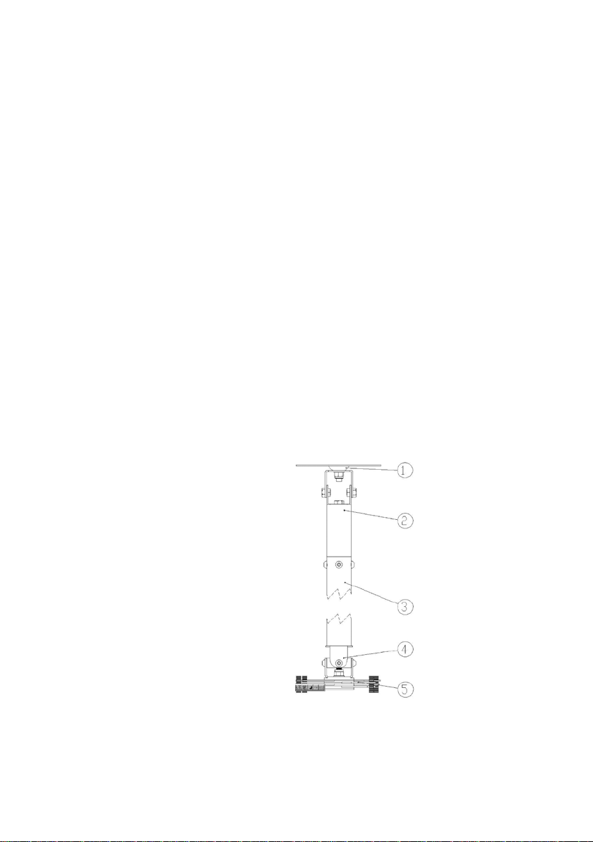
BRACKET PARTS
1. Ceiling Yoke
2. Top Coupler
3. 1.1m pole
4. Bottom Yoke
5. Universal “Spider” Fitting
TM-1200_manual_en_v1
3
Page 4
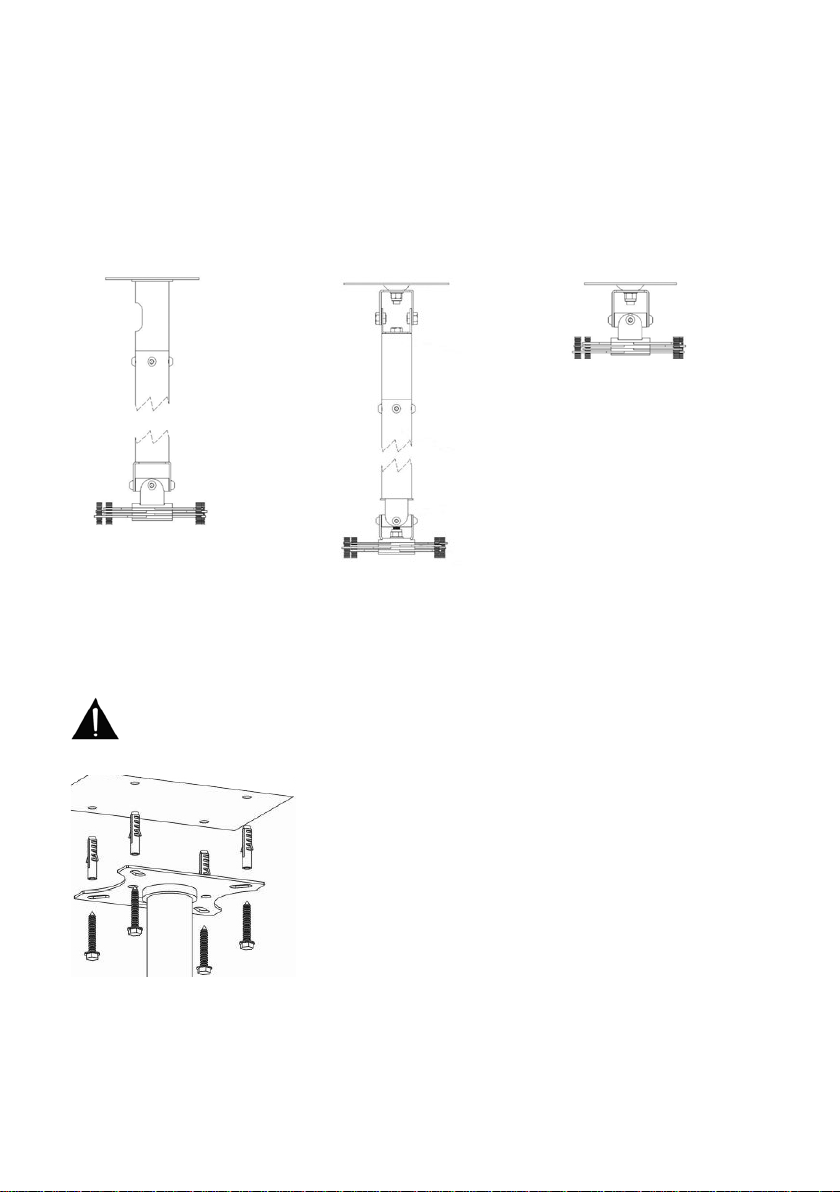
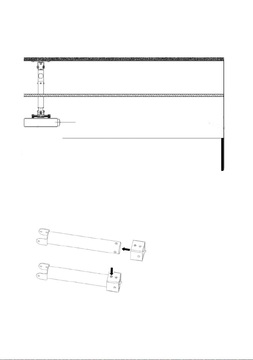
ALTERNATIVE ASSEMBLY CONFIGURATIONS
OPTION A
Standard configuration
INSTALLATION INSTRUCTIONS
Ensure the correct fixtures are used to attach the projector Techmount to
the wall or ceiling depending on the surface you are attaching to. The
fixtures provided are ST8x50 bolts with 10mm plastic inserts for attachment
to masonry. They may not be suitable for your application.
OPTION B
Sloped ceiling fitting
installed
OPTION C
Close-coupled
This bracket is designed to be m o dular, and interchange with brackets that use the same
2” (51mm) pole standard.
TM-1200_manual_en_v1
4
Page 5
ASSEMBLY FOR STANDARD / SLOPED CEILING CONFIGURATION:
1. Hold pole in place and mark length. The lens of projector should be around a foot above
the axis with top of screen.
2. Cut pole to length.
3. Drill new holes in the end of the pole :
a. Fit drilling jig
b. Use the included Hex key to tighten jig in place.
c. Place jig and pole on the ground. Drill four new holes.
d. Remove jig.
5
TM-1200_manual_en_v1
Page 6
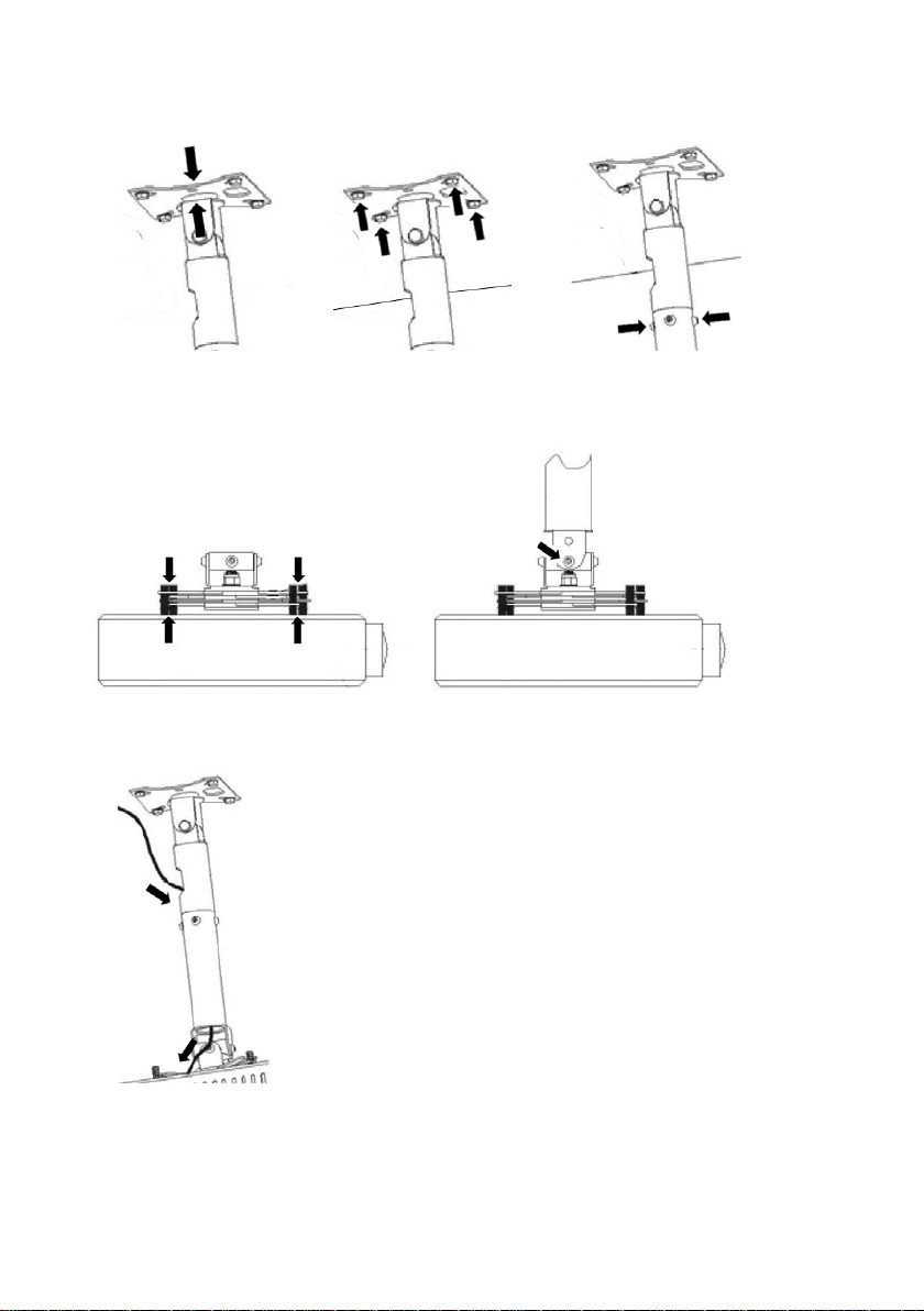
4. Attach top coupler and/or tilting mechanism to ceiling yoke. Fix to ceiling. Fix pole.
5. Attach projector to t h e s pider/bottom yoke f itting to the projector, and attach all to the
pole.
6. Thread the input and power cables through the bracket’s cable manag em ent s ystem.
6
TM-1200_manual_en_v1
Page 7
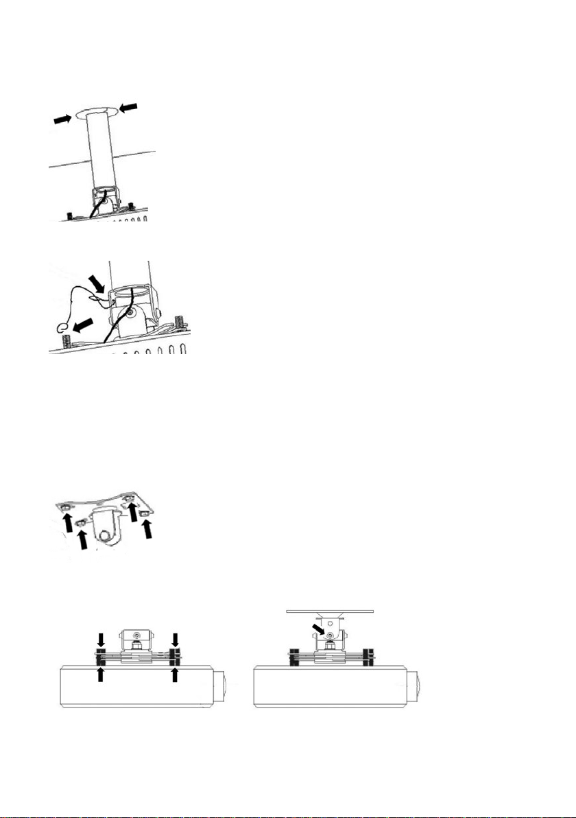
7. If you have a false ceiling, fit the included trim disk.
8. Fix fall-arrest cable to pole and projector.
9. Turn the projector on to calib r a te image and adjust tilt. Lock of f bottom yoke bolts.
ASSEMBLY FOR CLOSE-COUPLED CONFIGURATION:
1. Fix top yoke to the ceiling.
2. Attach the projector to the spider/bottom yoke fitting to the projector, and attach all to the
top piece of the tilting mechanism. Fix one end of fall-arrest cable to pole, and the other
end to projector.
TM-1200_manual_en_v1
7
Page 8

WARRANTY
This product comes with a 2-year return to base warranty, effective from the date of purchase.
This warranty applies only to the original purchaser an d is not transferable. For the a voidance of
doubt, this will be taken from the information held by the appointe d national distributor at the
point of sale. The liability of th e manufacturer and its appointed service company is lim ite d to
the cost of repair and or replacement of the faulty unit under warranty, except for death or
injury (EU85/374/EEC). This warranty protects you against the following:
• Faul ty w ields resulting in the prod u ct not safely performing its ta sk within the recommended
SWL (safe working load).
• Poor finishing resulting in the product not being able to be assembled.
• Exte rnal corrosion if identified within 24 hours of purchase. The inside of the pipe is not
powder-coated, so light corrosion may develop over tim e. This is normal and does not
adversely affect the load-bearing capability of the product, therefore it is not covered in this
warranty.
If you find you do have a problem with thi s product, you should contact the AV reseller you
purchased this product from. T h e original purchaser is responsible for shipment of the product
to the manufacturer’s appointed service centre for repair. We will endeavour to return repaired
units within 5 working days, howe ve r this may not always be possible in which case it will be
returned as soon as practica lly possible. This warranty does not protect this product against
faults caused by abuse, misuse, or incorrect installation which might be caused by ignoring the
guidelines set out in this man ua l. If failure is not covered by this warranty, the owner will be
given the option to pay for labour and parts to repair the unit at the service company’s standard
rate.
LEGAL DISCLAIMER: Because we are committed to improving our products, the details above
may change without prior warning. This User Manual is published wi tho ut wa rr a nty and any
improvements or changes t o the User Manual necessitate d by typographical errors, ina ccuracies
of current information, or improvements to programs and/or equipment, may be made at any
time and without notice. Suc h changes will be incorporate d into new editions of the Use r
Manual.
TM-1200_manual_en_v1
8
 Loading...