

Page 1
ENGINEERING
Ster eo
Page 2

Page 3

The instrument that you have just received is manufactured by Vision Engineering.
Vision Engineering is the world leader in the manufacture of Microscopes without eyepieces (known as
DYNASCOPES or LYNX), Microscopes with Expanded Pupils (known as COBRA) and stereo magnifiers
(known as MANTIS).
MANTIS, LYNX, COBRA and DYNASCOPES are available in a range of stereo and mono configurations.
They are used in a wide range of manufacturing industries, workshops and laboratories.
The systems are used for manual assembly and finishing, inspection, dimensional measurement and rework.
They also have considerable research, laboratory and biomedical uses.
Vision Engineering has manufacturing and distribution subsidiaries world-wide as follows:
GREAT BRITAIN:
Manufacturing Base and Headquarters
Vision Engineering Limited Tel: +44 (0) 1483 223417
Send Road Fax: +44 (0) 1483 223297
Send e-mail: 100721.1202@compuserve.com
WOKING
Surrey GU23 7ER
Commercial
Vision Engineering Limited Tel: +44 (0) 1483 248300
Monument House Fax: +44 (0) 1483 248317
Monument Way West e-mail: 100721.1202@compuserve.com
WOKING
Surrey GU21 5EN
U.S.A.:
Vision Engineering Inc Tel: +1 860 355 3776
570 Danbury Road Fax: +1 860 355 0712
New Milford e-mail: info@visioneng.com
Connecticut 06776
USA
Vision Engineering Inc Tel: +1 714 974 6966
745 West Taft Avenue Fax: +1 714 974 7266
Orange e-mail: alsilva@visioneng.com
California 92865
USA
ENGINEERING
Page 4

GERMANY: SWITZERLAND: AUSTRIA: CZECH REPUBLIC: SLOVAKIA:
Vision Engineering Limited Tel: +49 (0) 8141 40 1670
Anton Pendele Strasse 3 Fax: +49 (0) 8141 40 16755
D-82275 Emmering e-mail: sales@vision-eng.de
Germany
NORTH GERMANY: BENELUX: DENMARK: NETHERLANDS:
Vision Engineering Limited Tel: +49 (0) 2129 91 5900
Am Ideck 28 Fax: +49 (0) 2129 91 5903
D-42781 Haan
Germany
FRANCE:
Vision Engineering Limited Tel: +33 (0)1 64 46 90 82
Miniparc du Verger Fax: +33 (0)1 64 46 31 54
1 Rue de Terre Neuve e-mail: 100772.1206@compuserve.com
ZA Courtaboeuf
91967 Les Ulis Cedex
France
JAPAN:
Nippon Vision Engineering Tel: +81 (0) 45 472 1004
No. 6 Shinyokohama Hayama Building Fax: +81 (0) 45 472 1177
1-28-8 Shinyokohama e-mail: info@vision-eng.co.jp
Kohoku-ku
Yokohama-shi
Japan
All other countries are covered by distributors. Our contracted distributors are all fully trained in installation
and service and hold sales and service stock.
Your local distributor is:
Page 5

CONTENTS
Introduction
Packing Contents
Head Pack 1
Stand Pack or Platform Pack 1
Zoom Assembly Pack & Accessories 2
Assembly
Platform/Bench Assembly 3
Head to Tubular Support Assembly 3
Column to Stand Assembly 4
Column Attachment Assembly 5
Attaching Head 6
Objective Lens 6
Attaching 6 Point Ringlight 6
Attaching Spot Illuminator 7
Photographic Attachments 7
Zoom Multiplier 8
Mains Connection 8
Inserting Graticule 8
Operator Controls
Main System Controls 9
Graticule Adjustment 9
Routine Maintenance
General Maintenance Points 10
Sub-Stage Lamp Changing 11
Illuminator Lamp Changing 11
Page 6

Magnification & Optical Information
Lynx Magnification Table 12
Product Family
Family Tree 13
Warranty
Page 7
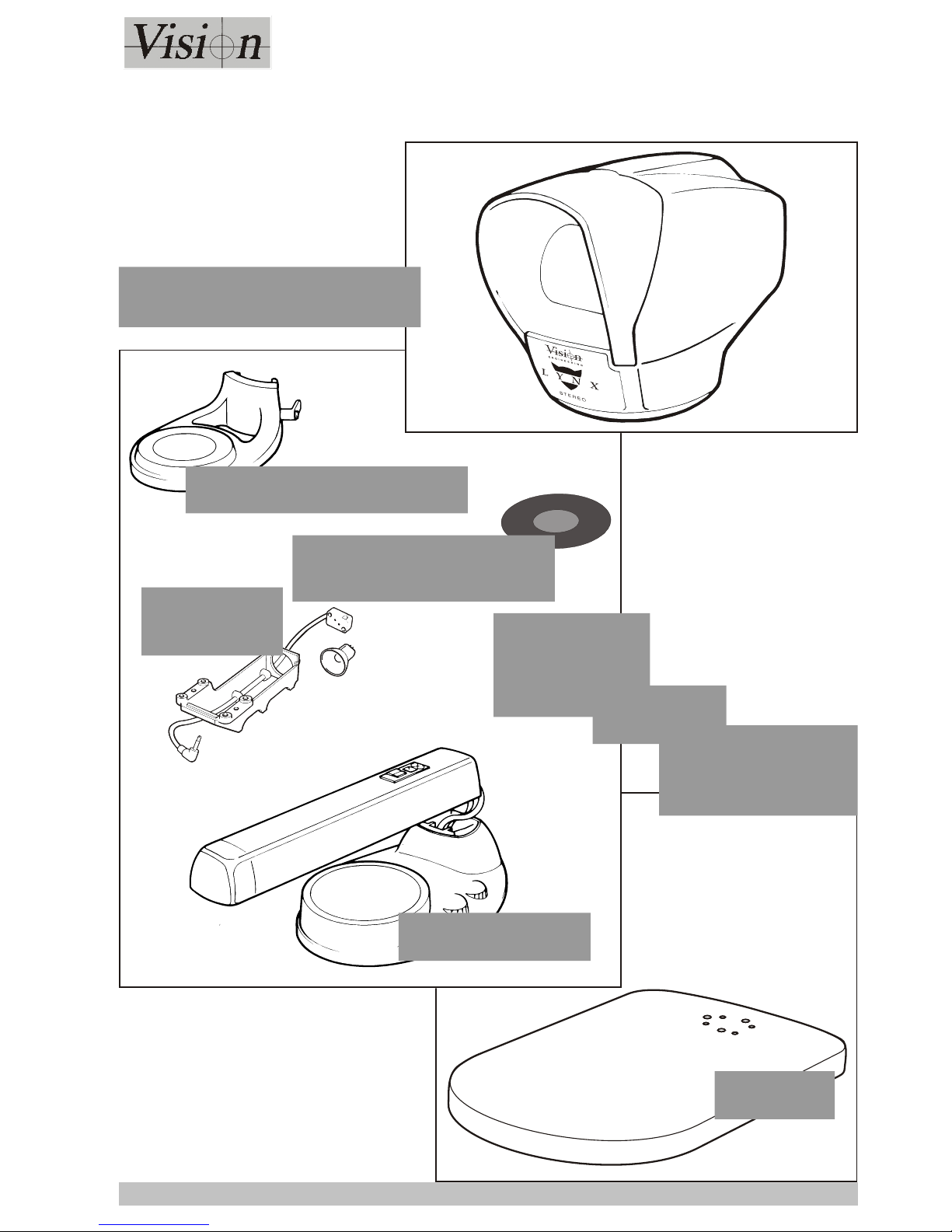
Please look for the following parts in each pack. Each pack has a check
list on the outside of its contents
PACKING CONTENTS
Page 1
PACKING CONTENTS
STAND
PACK
Column & Stand
Platform
Adjustable Subject Platform
HEAD PACK
Substage
Illuminator
PLATFORM
PACK
OR
Condenser Assembly with
Diffuser
Page 8

Page 2
PACKING CONTENTS
x 0.3
x 0.7
x 1.0
x 2.0
x 1.5
x 0.5
ZOOM PACK
Spot Lamp
Assembly
6 Point Ringlight,
Illuminator &
Power Supply
Objective
Lenses
Zoom/Focus
Assembly
Anti-glare
Shield
Spare Lamp
ACCESSORIES
PACKS
Zoom
Multiplier
Photographic
Adaptors &
Photo Arm
Upright &
Horizontal Boom
Bars
Stage
Boom Mount
Bracket
Page 9

ASSEMBLY
ASSEMBLY
Page 3
ASSEMBLY
3
4
Securing Bolts
& Pressure Cups
Bench Drilling Template
9mm Dia.
105mm Dia.
90.9mm
1
PLATFORM/BENCH ASSEMBLY
If bench mounting, drill holes in the
bench using the template shown 1 left.
Allow room for the horizontal support bar
to protrude behind the Lynx.
Feed the stand
securing bolts up
through the
pressure cups
and secure into
the stand base
(see 2 left).
Attach the horizontal
support bar to the
vertical bar as shown
in 3 above.
Slide the securing
collar up and lock it
into the desired
position (see 4
above).
HEAD TO TUBULAR
SUPPORT ASSEMBLY
Attach clamps to the horizontal post (see right).
Page 10

Page 4
ASSEMBLY
Stage
Blanking
Plate
Stage
Glass
1
Fan
Column
Securing Screws
Securing
Screw
Connector
COLUMN TO STAND
ASSEMBLY
Insert the Fan, connect it and lock it in position
with its securing screw (see inset 1).
Raise the column into the upright position and
secure it with the four column securing screws.
Remove the Blanking
Plate.
Remove the stage
glass and lower the
Stage onto the Stand.
Secure it with the 4
bolts supplied.
Page 11

Page 5
ASSEMBLY
1
2
Mirror
Blanking
Plate
Column
Connector
Column
Cap
Zoom/Focus
Assembly
Adjustable Subject
Platform
Sub-Stage
Illuminator
Condenser
Plate &
Diffuser
COLUMN
ATTACHMENT
ASSEMBLY
Sub-stage illuminator Remove the protective film from
the mirror (see right). Fit the
bulb (see 1 and 2 right).
Remove the Blanking Plate.
Slide the sub-stage illuminator
into position and secure it with
the two bolts supplied. Connect
the assembly. Put the
condenser plate into position
and fit the diffuser in either the
base or subject platform as
required.
Adjustable Subject Platform -
Slide the platform on to the
column, position it as required
and secure it in position.
OR
Slacken the securing clamp
until the platform can be
pushed on to the column.
Re-tighten the clamp with the
platform in the required
position.
Zoom/Focus Assembly Remove the Column Cap. Slide
the assembly on to the column
just enough to allow the column
connector to be attached to the
male connector at the rear of
the assembly. Replace the
Column Cap.
Position the Zoom/Focus
Assembly as required
and secure it.
Page 12

Page 6
ASSEMBLY
Head
Connector
Head
Socket
Alignment Pin
Securing Screw
Insert the Head
Connector in the Head
Socket. Place the Head
on to the Zoom/Focus
Assembly, ensuring the
alignment pin in the
Zoom/Focus Assembly
lines up with the relevant
slot in the Head. Tighten
the securing screw.
ATTACHING HEAD
Securing
Screws
Objective
Lens
6 Point
Ring Light
Beam
Converger
(only for 1.5x or 2x lens)
Place the ringlight into position and tighten the
securing screws. Clip the Beam Converger (only
required if using a 1.5x or 2x objective lens) into
place and attach the fibre optic cable to the
illuminator.
ATTACHING
6 POINT RINGLIGHT
Objective
Lens
Lens
Securing Screw
OBJECTIVE LENS
Page 13

Page 7
ASSEMBLY
Head
Connector
Photographic
Attachment
Camera
Interface
Head
Socket
Securing Screw
Head
Securing Screw
Remove the Head.
Place the
Photographic
Attachment
Assembly into
position and tighten
the securing screw.
Replace the head
on to the assembly
and tighten the
Head Securing
Screw.
Attach the
appropriate Camera
interface to the
Photographic
Attachment and
tighten the securing
screws.
NOTE
Adapters for the
Polaroid, 35mm
and CCTV/Digital
cameras are
different.
The camera
attaches to the
interface.
PHOTOGRAPHIC
ATTACHMENTS
Objective Lens
Spot Illuminator
Connector
Spot
Illuminator
Securing
Screws
Place the Spot Illuminator into position and
tighten the securing screws. Insert the
illuminator’s connector into the socket
underneath the Zoom/Focus Assembly.
ATTACHING
SPOT ILLUMINATOR
Page 14

Page 8
ASSEMBLY
Securing Clip
Retaining Knobs
Graticule
Connect Mains
at Rear
1
15
2
3
0
Mains
On/Off
Switch
Anti-glare
Shield
Mains
Input
Voltage
Selector
Fuse
MAINS
CONNECTION
Head
Connector
Zoom
Multiplier
Head
Socket
Securing Screw
Head
Securing Screw
ZOOM MULTIPLIER
Remove the Head. Place the Zoom
Multiplier Assembly into position and
tighten the securing screw.
Replace the Head on to the assembly
and tighten the Head Securing
NOTE
Ensure the Voltage Selector is
turned to the correct setting.
For Japan and some Far
Eastern markets the voltage
selector is marked 100 - 110V.
INSERTING
GRATICULE
Squeeze the securing
clip at the base of the
front cover and lift the
cover off. Loosen the
appropriate retaining
knob (the graticule
can be placed on
either side of the
head), slide the
graticule into position
and re-tighten the
knob. Replace the
front cover.
Attach the anti-glare shield as
shown left.
Page 15

ASSEMBLY
OPERATOR
CONTROLS
Page 9
OPERATOR CONTROLS
Securing Clip
Graticule
Retaining Knobs
Rotation Spigot
Focus
Control
Head Height
Adjuster
Subject Platform
Height Adjuster
Top Illuminator
Dimmer
Substage Illuminator
Dimmer
Zoom
Control
Magnification
Control
Low
(1x)
High
(1.5x or 2x)
MAIN SYSTEM CONTROLS
ORDER OF SETTINGS
1. Turn the Zoom
control to maximum.
2. Set the Focus
control to obtain the
best clarity.
The focus will now be
maintained throughout
the Zoom range.
Squeeze the securing
clip at the base of the
front cover and lift the
cover off.
To focus and centralize
the graticule, loosen the
appropriate retaining
knob and move the
graticule up or down for
focus and sideways to
centralize. Re-tighten
the retaining knob.
To adjust the graticule
rotationally, remove the
rotation spigot from its
storage position in the
graticule, insert it in the
rotation ring as shown
and rotate it until the
correct position is
obtained. Replace the
spigot and close the
front cover.
GRATICULE ADJUSTMENT
Page 16

ROUTINE MAINTENANCE
Page 10
ROUTINE MAINTENANCE
Viewing
Screen
1
1
5
2
3
0
Voltage
Selector
Input
Power
Fuse
Base
Securing
Screws
Rubber
Feet
Sub-Stage
Fuse
Securing Clip
Retaining Knobs
Graticule
Clean the viewing screen periodically with optical cloth.
GENERAL
MAINTENANCE
POINTS
If, after cleaning the
viewing screen, the
picture quality is
below standard,
remove and clean the
graticule if fitted.
If the graticule
requires adjustment
after it has been
cleaned, see page 9.
NOTE
Ensure the Voltage Selector is
turned to the correct setting.
For Japan and some Far
Eastern markets the voltage
selector is marked 100 - 110V.
Changing the
Sub-Stage Fuse:
Remove the 4 rubber
feet from the base
(push fit).
Remove the 5 base
securing screws.
Replace the fuse with
an 800mA quick
blow type.
NOTE
When the base is
replaced, ensure
the heat slots line
up with the heatsink
and substage bulb.
Page 17

ROUTINE
MAINTENANCE
Page 11
ROUTINE MAINTENANCE
Condenser &
Diffuser
Plate
Sub-Stage
Illuminator Bulb
20W/12V
Dichroic Lamp
(2000 hour)
2
3
1
150W/21V
Halogen Lamp
(200 hour)
NOTE:
ENSURE THE ILLUMINATOR
IS NOT HOT.
Press down the bulb/fan
assembly release button (see
1 above).
Lift out the bulb/fan assembly
(see 2 above).
Disconnect the lamp as
shown in 3 above.
When relocating a lamp,
ensure it is fully pushed into
the lamp holder.
SUB-STAGE LAMP CHANGING
ILLUMINATOR
LAMP
CHANGING
NOTE:
The 250W
Halogen lamp
version (60 hours)
has the same
lamp change
procedure
Page 18

Page 12
MAGNIFICATION & OPTICAL INFORMATION
PART
NUMBER
MAGNIFICATION RANGE
WITH 1.5x
MULTIPLIER
(C-040)
WITH 2x
MULTIPLIER
(C-041)
WORKING
DISTANCE
FIELD OF VIEW
AT MAX. ZOOM
FIELD OF VIEW
AT MIN. ZOOM
NOTES
C-050 x0.3 x2.1 - x12 x3.2 - x18 x4.2 - x24 312mm 12mm 77mm
Requires diverging lens when
used with 6 point ringlight
C-055 x0.5 x3.5 - x20 x5.3 - x30 x7.0 - x40 175mm 7mm 46mm
C-051 x0.7 x4.9 - x28 x7.4 - x42 x9.8 - x56 127mm 5mm 33mm
C-052 x1.0 x7.0 - x40 x10.5 - x60 x14 - x80 85mm 3.5mm 24mm
C-053 x1.5 x10.5 - x60 x15.8 - x90 x21 - x120 45mm 2.5mm 16mm Requires converging lens (Part
No. C-034) when used with 6
point ringlight
C-054 x2.0 x14 - x80 x21 - x120 x28 - x160 25mm 1.75mm 12mm
Note: Above figures without
multipliers fitted. To
calculate field of view =
140mm
magnification
MAGNIFICATION & OPTICAL INFORMATION
LYNX MAGNIFICATION TABLE
Page 19

PRODUCT FAMILY
Page 13
PRODUCT FAMILY
STANDARD
Core Instrument
Stereo Zoom
C-002
Head L-001
Bench
Stand
C-010
6-Point Ringlight C-023/024
& 150W Illuminator C-030
150W/21V Transformer
(Head & Ringlight)
C-031 100V
115V
220V
240V
Coaxial (through
the lens illuminator)
C-139
250W Illuminator
C-028
250W/24V
Transformer
(Head & Ringlight)
C-029
60W/12V
Dual Transformer
(Head & Spots)
C-034 100V
115V
220V
240V
Spot Illuminator
C-021
Diffuser
Plate
Clear Glass
Insert
Condensor
Base
Adaptor
High Intensity
Substage Illuminator
& Diffuser Kit
C-020
Floating
Stage
C-070
Zoom
Multiplier
(x1, x1.5)
Zoom
Multiplier
(x1, x2)
25° Angle
Adjuster
Dust Cover
C-103
Photographic
Attachment
C-069
Polaroid Camera
C-061
Digital Camera/
CCTV Camera
C-063
35mm Camera
C-062
Adjustable
Subject
Platform
C-011
C-040
C-041 C-152
Objective
Lenses
0.3x C-050
0.5x C-055
0.7x C-051
1.0x C-052
1.5x C-053
2.0x C-054
Boom Mount
C-145
Lynx Stereo
FOR INSPECTION AND GENERAL MICROSCOPE APPLICATIONS
ENGINEERING
Platform Base
for Boom Mount
C-155
Boom Mount
mounted on
work surface
or Platform Base
C-145
Polariser Kit
C-096
50mm x 50mm (2“ x 2”)
Measuring Stage
C-136
Cross Line NE8 Graticule
C-134
In line Viewing
Adaptor
C-147
Boom Mount/
Stereo Zoom
OEM C-146
OEM Mounting Clamp
(available separately)
C-149
Head L-001
Mounting Brackets for Transformer and Illuminators
when used with Boom Mount (2 required)
C-148
FAMILY TREE
Page 20

Page 21

WARRANTY
This product is warranted to be free from defects in material and workmanship for a period of one year from the date of
invoice to the original purchaser.
If, during the warranty period the product is found to be defective, it will be repaired or replaced at facilities of Vision
Engineering or elsewhere, all at the option of Vision Engineering. However, Vision Engineering reserves the right to
refund the purchase price if it is unable to provide replacement, and repair is not commercially practicable or cannot
be timely made. Parts not of Vision Engineering manufacture carry only the warranty of their manufacturer.
Expendable components such as lamps and fuses carry no warranty.
This warranty does not cover damage caused in transit, damage caused by misuse, neglect, or carelessness, or
damage resulting from either improper servicing or modification by other than Vision Engineering approved service
personnel. Further, this warranty does not cover any routine maintenance work on the product described in the
instruction manual or any other minor maintenance work which is reasonably expected to be performed by the
purchaser.
No responsibility is assumed for unsatisfactory operating performance due to environmental conditions such as
humidity, dust, corrosive chemicals, deposition of oil or other foreign matter, spillage, or other conditions beyond the
control of Vision Engineering.
Except as stated herein, Vision Engineering MAKES NO OTHER WARRANTIES, EXPRESS OR IMPLIED BY LAW,
WHETHER OR MERCHANTABILITY, FITNESS FOR A PARTICULAR PURPOSE OR OTHERWISE. Further, Vision
Engineering shall not under any circumstances be liable for incidental, consequential or other damages.
ENGINEERING
 Loading...