

Page 1
1
AV-1700_manual_en.doc
AV-1700 DIGITAL AMPLIFIER
OWNERS MANUAL
www.visionaudiovisual.com/techaudio/av-1700
Page 2

2
AV-1700_manual_en.doc
DECLARATION OF CONFORMITY
Where appli cable Vision pr oducts are ce rtified and comply wit h all known loc al regula tions to a
‘CB Cer t ificatio n’ stand ard. Vision commits to ensure all p r oduct s are fully compliant wit h all
applicable certification standards for sale in the EU and other participating countries.
The product described in this owner manual is in com pliance wit h RoHS (EU directive
2002/95/EC), and WEEE (EU directive 2002/96/EC) standards. This product should be returned
to the place of purchase at the end of its useful life for recycling.
WARNINGS
CAUTION: TO REDUCE THE RISK OF ELECTRIC SHOCK DO NOT REMOVE COVER (OR
BACK). NO USER-SERVICEABLE PARTS INSIDE. REFER SERVICING TO QUALIFIED
SERVICE PERSONNEL.
The lightning flash with arrowhead symbol, within an equilateral triangle, is intended to alert the
user to the presence of uninsulated “dangerous voltage” within the product’s enclosure that may be
of sufficient magnitude to constitute a risk o f electric shock to persons.
The exclamation point within an equilateral triangle, is intended to alert the user to the presence of
impo rtant oper ating and maintenance (servicing) instructions in the literature accompanying the
appliance.
WARNING: TO REDUCE THE RISK OF FIRE OR ELECTRIC SHOCK, DO NOT EXPOSE
THIS APPLIANCE TO RAIN OR MOISTURE.
All products are designed and imported into the EU by ‘Vision’ who is wholly owned by ‘ A z lan
Logistics Ltd.’, Registered in England Nr. 04625566 at Lion House, 4 Pi o ne er Bus i ness Park,
Clifton Moor, York, YO30 4GH. WEEE Registra tion: GD0046SY
DECLA RATI ON OF OR I GIN
All Vision products are made in the People’s Repub lic of China ( PRC).
Page 3

3
AV-1700_manual_en.doc
USE ONLY D OMESTI C AC OUTLETS
Connecting the unit to an outlet supplying a higher voltage may create a fire hazard.
HANDL E T HE POWER CORD WITH CARE
Do not disconnect the plug from the AC outlet by pulling the cord; always pull the plug itself.
Pulling the cord may damage it. If you do not intend to use your unit for any considerable
length of time, unplug the unit. Do not place furniture or other heavy objects on the cord, and
try to avoid dropping heavy objects on it. Do not tie a knot in the power cord. Not only could
the cord be damaged, but a short circuit could also be caused with a consequent fire hazard.
PLACE OF INSTALLATION
Avoid installin g this pr oduct unde r the followin g conditio ns:
• Moist or humid places
• Places exposed to direct sunlight or close to heating equipment
• Extr emely cold locations
• Place s subject t o exces sive vibrati on or dust
• Poor ly ventilat ed places
Do not expose this pro d uct to dripping or splas hi ng . DO NOT PLACE OBJECT S FI LLED WITH
LIQUI D S ON OR NEAR THIS PRODUCT!
MOVING TH E UNIT
Before moving the unit, be sure to pull out the power cord from the AC outlet and disconnect
the interconnection cords with other units.
WARNING SI GNS
If you detect an abnormal smell or smoke, turn this product off immediately and unplug the
power cord. Contact your reseller or Vision.
PACKAGING
Save a ll packing material. It is essent ial for shipping in th e event the unit ev er needs repair.
IF ORIGINAL PACKAGING IS NOT USED TO RETURN THE UNIT TO THE SERVICE CENTRE,
DAMAGE IN TRANSIT WILL NOT BE COVERED BY WARRANTY.
WATTS
The most consistent standards for measuring watts are “Program Power” and “RMS” because
these measure average sustained levels.
Amplifier power output changes depending on how many loudspeakers are connected.
Professional manufacturers typically quote output based on 8 ohms. Less reputable
manufacturers quote at 4 ohms to make their product seem more powerful.
This amplifier has an output of:
2 x 30w (sometimes referred to as 60w) @ 8 ohms (two loudspeakers connected)
2 x 60w (sometimes referred to as 120w) @ 4 ohms (four loudspeakers connected)
Page 4
4
AV-1700_manual_en.doc
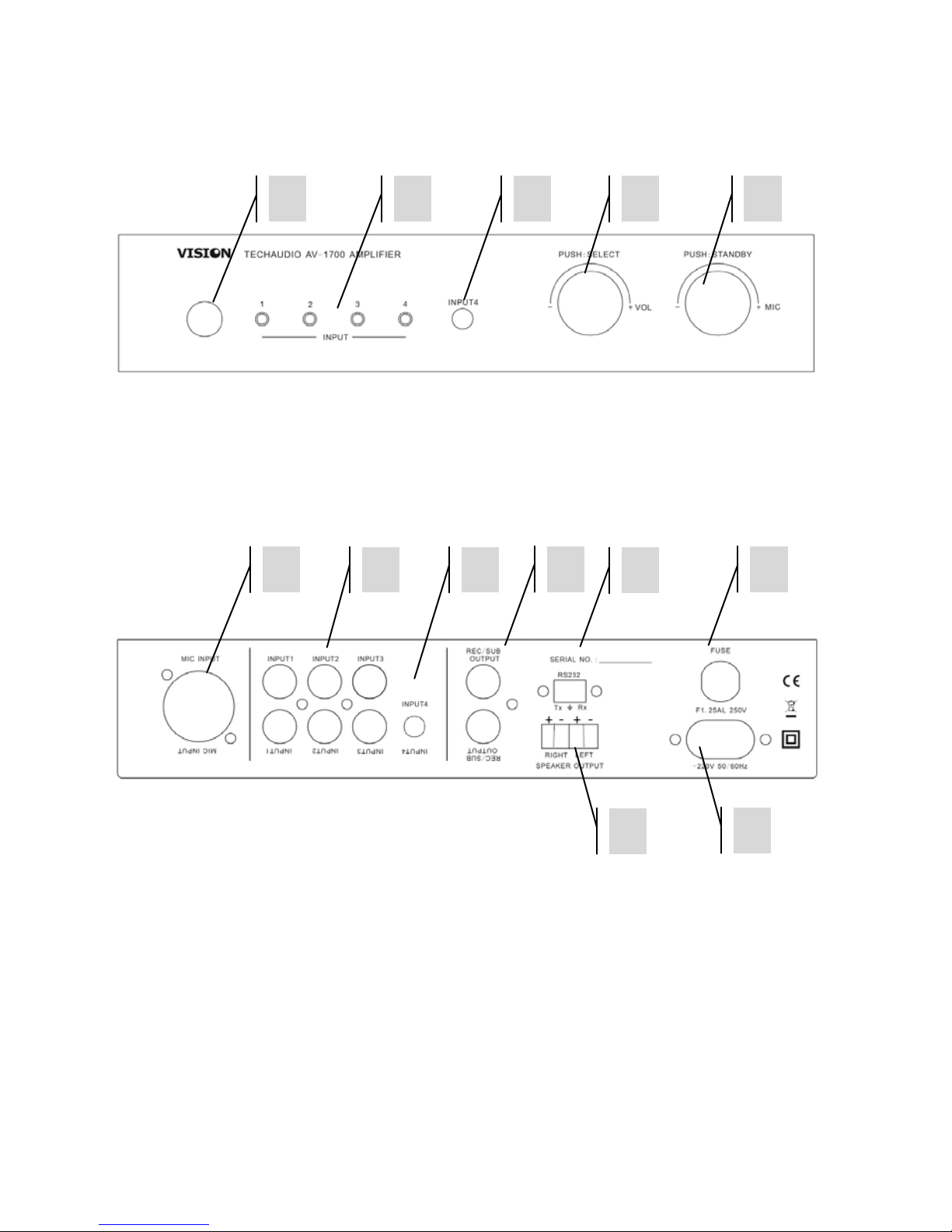
FRONT AND RE AR PANELS
1. IR Receiver
2. Active Input LED
3. Line-level Input 4 (3.5mm Minijack - duplicated on rear panel)
4. Line-level Input Volume [Push: Input Select]
5. Microphone Input Gain [Push: On/Off]
1. Microphone Input (Balanced XLR)
2. Line-level Inputs 1-3 (2-Phono)
3. Line-level Input 4 (3.5mm Minijack -duplicated on front panel)
4. Line-Level Output (2-Phono)
5. Loudspeaker Outputs
6. RS-232 Control Input
7. Fuse
8. Figure-8 (C8) Power Input
1 3 4 5 2 1 2
3
4
6 8 7
5
Page 5

5
AV-1700_manual_en.doc
REMOTE CON T ROL
1. Power On and Off
2. Input Selection
3. Tone Reset
4. Mute
5. Tone Control
6. Microphone Input Gain
7. Line-level Input Volume
1 2 3 4 5 6 7
Page 6

6
AV-1700_manual_en.doc
INSTALLATION
1. CONNECT INPUTS AND OUTPUTS Up to two pairs of loudspeakers can be connected. If
speaker cable provided is not long enough use unshielded speaker cable with gauge of
0.75mm or higher.
NOTE 1: The warranty will be void if you use shielded cable
NOTE 2: This is a low-impedanc e digital amplifier. Do not connect ‘100v line’ speakers
(normally any speakers with “t” in their part code)
2. CONNECT POWER The amplifier will t urn on when power is plugged in the fir s t time.
3. TURN POWER ON Then select input and adjust volume as required.
Should it become overloaded it will shu t d o wn to protect it self. Return operating conditions to
safe levels and re start amplifier.
MICR OPHO NE INPUT
1. The microphone input provides “Phantom Power” (24v) for condenser microphones such as
lectern or boundary (PZM) microphones.
NOTE: Ensure the microphone volume is turned down when connecting microphones.
2. The microphone volume can be adjusted independently of the line-level inp uts.
3. Keep microphone away from loudspeakers to avoid feedback.
Page 7

7
AV-1700_manual_en.doc
RS-232 CODES
Table 1: Control Codes
Codes
On Remote
Function
0x11
ON
Bring out of standby
0x15
OFF
Put into standby
0x05
MUTE
Mute on/off (Standby activates after 30 minutes of mute)
0x01
INPUT1
Input select 1
0x09
INPUT2
Input select 2
0x10
INPUT3
Input select 3
0x02
INPUT4
Input select 4
0x08
TREBLE+
Increase treble gain by +1dB
0x0D
TREBLE-
Decre as e t reble gai n by -1dB
0x0C
BASS+
Increase bass gai n by + 1dB
0x12
BASS-
Decre as e bas s gain by -1Db
0x00
RESET
Reset tone
0x07
MIC+
Mic volume + (also ca ncels mute if active)
0x0B
MIC-
Mic vol ume - (also cancels mute if active)
0x06
VOL+
Volume + (also cancels mute if ac tive )
0x04
VOL-
Volume - (als o cancels mute if activ e)
Page 8

8
AV-1700_manual_en.doc
Table 2: Return Codes
Codes
Function
Range
Remark
working
off
standby
MUTE
Mute status
0 1 0 1 1
BD3490FV_SELECT
Input select
0 3
BD3490FV_GAIN_GET
Get master volume
1
28(1C)
BD3490FV_B_GAIN_GET
Get bass gain
1
15(0F)
BD3490FV_T_GAIN_GET
Get treble gain
1
15(0F)
PT2259_GAIN_GET
Get mic gain
1
28(1C)
Baud rate: 2400K
Stop Bit: 1
Delivery interval >80ms
Send 0xA5 (hex code) as verification code
When a command is sent twice the amplifier returns the value of table 2
NOTE: Auto-Standby activates after 30 minutes of mute or no operation. Any adjustment turns
stand by off.
Page 9

9
AV-1700_manual_en.doc
TROUBLESHOOTING
If your system is not operating properly, please refer to the following information. If the
problem persists, disconnect from power and contact your AV reseller immediately.
Problem
Correction
No Sound
• Turn off and check connections.
• Check output level from sources. For example, laptop
volume.
Microphone quiet
• Some microphones have a gain switch. Consult the
manual.
No Power light
• Check power connections
• Abnormal load. Turn power off, disconnect some
speakers and test again
Distortion
• Input gain too high
• Volume too high
• Loudspeakers may be worn or damaged
Feedback
• Turn microphone down, or move away from speakers
Sound only coming out
one side
• Adjust balance control
• Turn off and switch output connections.
If the side changes the amplifier is okay – the fault is
with the speakers.
• Switch input connections and check input cabling.
Page 10

10
AV-1700_manual_en.doc
SPECIFICATIONS
AMPLIFIER DIM ENS IONS: 220 x 15 4 x 44 m m (wide x deep x tall) not inc luding dials and
connectors
AMPLIFIER WEIGHT: 1.2kg
COLOU R: W hi t e
INPUTS
4 x Stereo inputs (via 3 x phono connectors / 1 x 3.5mm minijack)
1 x Microphone inputs via balanced XLR
OUTPUTS
1 x Stereo Line-le vel output via phono connectors
TECHNICAL DETAILS
2 x 30w @ 8 ohms
Total Harmonic Distortion <2%
Frequency response (line in): 50Hz~18kHz
Signa l to noise ra tio (line in): 75dB
Rating input level/Impedance:
line in 440~500mV/47kohms
Power consumption (rating condition): <=125W
POWER SUPPLY: 100~240V Internal Power Supply
COMPLIANCES: RoHS, WEEE & C E com pliant
ACCE SSORIE S INCLUDE D
1 x 2-phono to 2-phono cable 2m long
1 x 3.5mm to 3.5mm minijack cable 2m long
2 x Unshielded Speaker Cable 5m long
1 x UK C7 figure-8 power cable 1.8 m long
1 x EU C7 figure-8 power cable 1.8 m long
1 x AU C7 figure-8 power cable 1.8 m long
1 x US C7 figure-8 power cable 1.8 m long
Page 11

11
AV-1700_manual_en.doc
WARRANTY
This product comes with a 2-year return to base warranty, effective from the date of purchase.
This warranty applies only to the original purchaser and is not transferable. For the avoidance of
doubt , th is will be taken from the information held by the appointed national distributor at the
point of sale. If the product is DOA (dead on arrival), you have 21 days from purchase date to
notify the national distributo r via your AV reseller. The liability of the manufacturer and its
appointed service company is limited to the cost of repair and/or replacement of the faulty unit
under warranty, except for death or injury (EU85/374/EEC). This warranty protects you against
the following:
• Failure of any co mponents , in cludin g the power supply.
• Damage when the product is first removed from its packaging if reported within 24 hours of
purchase.
If you find you do have a problem with this product, you should contact the AV reseller you
purchased this product from. The original purchaser is responsible for shipment of the product
to the manufacturer’s appointed service centre for repair.
We will endeavou r to return repa ir ed units within 5 work ing days, howeve r this may not always
be possi ble, in which case it will be retur ned as soon as practicably possible. In line wit h our
WEEE commitments, the manufacturer endeavours to replace the faulty parts of the product
rather than replacing the whole unit. This warranty does not protect this product against faults
caused by abuse, misuse, incorrec t in s t allat ion , unstable o r faulty power input, wh ich might be
cau sed by ignoring the guidelines set out in this manual.
LEGAL DISCLAIMER: Because we are committed to improving our products, the details above
may change without prior warning. This User Manual is published without warranty and any
improvements or changes to the User Manual necessitated by typographical errors, inaccuracies
of current information, or improvements to programs and/or equipment, may be made at any
time and without notice. Such changes will be incorporated into new editions of the User
Manual.
 Loading...