

Visicomm Industries 160KSS360400/50400, 160KSS360400, 160KSS350400 User Manual

USER’S MANUAL
160KSS360400/50400
2nd Edition
Frequency Converter
Visicomm Industries LLC
911A Milwaukee Ave.
Burlington, WI 53105

CONTENTS
USER’S MANUAL....................................................................................................1
1. SYSTEM OVERVIEW........................................................................................3
1.1. CONSTRUCTION OF THE UNIT................................................................3
1.2. FEATURES AND ADVANTAGES..............................................................3
1.3. FRONT PANEL ............................................................................................5
2. INSTALLATION.................................................................................................7
2.1. SITE & ENVIRONMENT CONSIDERATIONS...........................................7
2.2. CABLE SELECTION...................................................................................9
3. OPERATIONS..................................................................................................11
3.1. POWER START UP PROCE DURE .........................................................11
3.2. SHUTDOWN PROCEDURE .....................................................................12
4. LCD DISPLAY..................................................................................................13
4.1. MENU 0 - MAIN MENU.............................................................................13
4.2. MENU 1 - SELECT MENU........................................................................13
4.3. MENU 2 – PARAMETER SET..................................................................14
4.4. MENU 3 – DATE / TIME............................................................................15
4.5. MENU 4 – REAL TIME DATA..................................................................15
4.6. MENU 5 – RECTIFIER DATA ...................................................................16
4.7. MENU 6 – DC DATA.................................................................................16
4.8. MENU 7 – OUTPUT DATA.......................................................................16
4.9. MENU 8 – OTHER DATA.........................................................................17
4.10. MENU 9 – STATUS/WARN/FAULT......................................................17
4.11. MENU 10 – HISTORICAL DATA..........................................................18
5. REDUNDANCY ( SYSTEM BACK – UP )......................................................19
6. HELP.................................................................................................................20
©2003, Visicomm Industries. All rights reserved. This book, or any part of it, must not be reproduced in any form
without permission of the copyright owner.
1. SYSTEM OVERVIEW
1.1. CONSTRUCTION OF THE UNIT
WARNING!
Be sure to operate the converter within its rated capacity.
Prevent direct exposure to sunlight, rain, or any other contaminating environment.
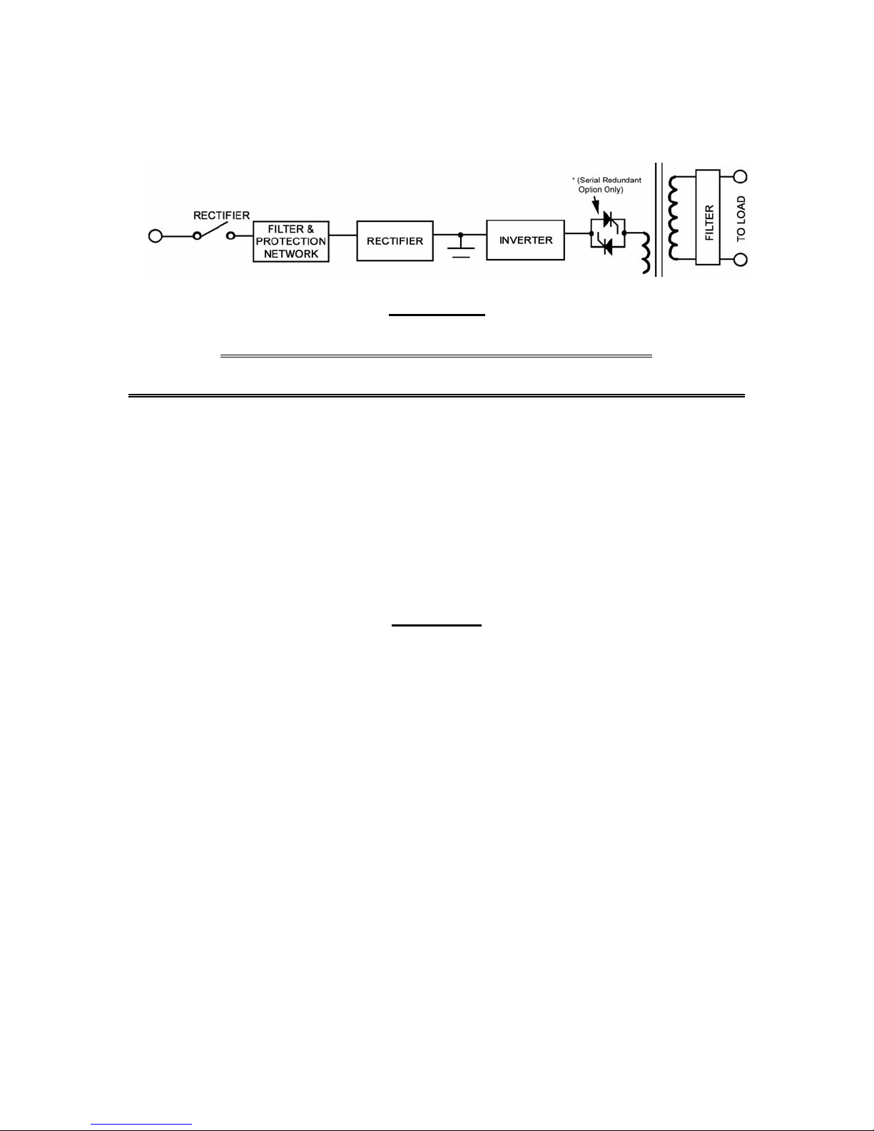
The System is composed of an input breaker, input filter & protection network, rectifier, inverter, isolation
transformer and output filter. The basic topology is shown in the diagram above. Operating in the normal AC
mode, energy from the 3 Phase AC source is converted to DC power and supplied to the inverter. The
inverter converts the DC power to three phase AC power and supplies the static switch, which allows the unit
to disconnect from the load. The power is then fed through an isolation transformer and an output filter to the
load.
When the inverter is in an abnormal condition, such as over temperature, short circuit, abnormal output
voltage, or overloaded for a period exceeding the inverter current limit, the inverter will automatically
shutdown, in order to protect itself from damage.
CAUTION!
Hazardous voltage exists inside the Unit (Which includes the connection terminals). Cable connection and
maintenance should be done by professional or qualified personnel.
DC capacitors are employed in this Unit; hazardous voltages still exist even when the Unit is not
energized. Do not touch any part inside of the Unit.
1.2. FEATURES AND ADVANTAGES
a. Reliable input protection: Circuit breakers are placed in each individual input phase.
b. Input surge protection: MOV (surge protectors) are added at the input, providing sufficient protection to
both the UNIT and the load from any lightning or surge caused by neighboring large loads.
c. EMI suppression: An EMI filter is added to meet the international EMC limits. Therefore,
very low noise is emitted, to prevent interference to other equipment connected to the same AC
source.
d. Ruggedness: The rectifiers employ phase control technology to regulate the DC bus voltage. SCRs
are employed as rectifiers to take advantage of their ruggedness under poor conditions. In addition,
inductors are used at the input to avoid deforming the AC source waveform.
* Option: The solid state transfer switch is supplied as an option for use in serial redundant systems (see page 19 for details)

e . High frequency design: The inverter uses high frequency, high efficiency IGBTs, and PWM to convert
the DC power to AC power. The number of components is reduced, resulting in increased reliability,
smaller size and weight, less transportation cost, improved performance, and the elimination of
acoustic noise.
f. True Galvanic isolation: An isolation transformer is used at the output. This solves the problem of
poor input grounding and will accept a different ground between input and output. Ground the output
to a known earth connection. This avoids the annoying problem of ground leakage current and allows
the output to be tied to any potential provided on site. The AC output is isolated under every mode of
operation. In addition common mode noise from the output isolation transformer is attenuated.
g. Modular design: The power circuit is separated into several modules plugged into slots in the UNIT,
which are easy to remove, permitting quick maintenance and easier trouble shooting (before the DC
bus is energized).
h. Multi-CPU design: Several CPUs are employed in the control circuit, critical functions are d esigned in
parallel to improve reliability. Therefore, in case of one CPU fails; the other CPUs can assume control
to maintain the output AC.
i. Operator errors: The UNIT is designed with breaker on/off sensors, power supply sensors, etc. to
prevent user errors from damaging the UNIT.
j. Wide input range: The UNIT is designed to accept an extra wide input range, so that it can work
comfortably under poor AC source conditions. Also, all the input components used are specially
selected to handle extreme high voltage and high current.
k. Extreme environment: Each component of the UNIT is chosen with a large safety margin to accept
extreme environmental conditions, such as temperature, humidity, altitude, shock, and contamination.
l. Extended MTBF of fans: Fans will slow down under light load, so that the life expectancy of the fans is
longer than specified.
m. Data log capability: Every abnormal condition will be stored in the converter for further reference. The
data is stored with the date and time (with a real time clock). When an abnormal condition occurs, the
user can get a full record of what has occurred. The data will not be erased even when all the power is
switched off.
n. Convenient panel design: The LCD display control switch is accessible through the up/down/enter
switch on the front window, which means one can read all the UNIT data without opening the front
door. Of course, the important inverter on/off switch is hidden behind the door (a key is needed to
open it, but you can also switch the inverter on or off from the front window by entering the correct
password in case the key is not at hand or lost), so that it is not easy to accidentally switch the UNIT on
or off.

1.3. FRONT PANEL
The front panel gathers the real time information of the UNIT and displays the data clearly. It also provides
switches for controlling and setting the UNIT. Each part of the panel is explained below:
A. LCD display- Real time status, data, and historical events are displayed on the LCD. The UNIT
parameters, real time clock, inverter, buzzer also can be set through this LCD. The LCD is back lit by
LEDs to provide a clear display, In order to lengthen the LED’s life time, they will be autom atically shut
off 3 minutes after no key is activated, and will light up again when one of the keys are pushed.
B. STATUS LEDs- 25 LEDs representing all of the important information of the UNIT will provide current
information to the user. Therefore these LEDs are especially important when abnormal conditions
occur. The 25 status indicators are:
1. INVERTER ON – the inverter is running.
2. LOAD CONNECTED – the inverter is connected to the output terminals.
3. SHORT CIRCUIT – the output is in a short circuit status.
4. FUSE/OVER TEMP SD – the inverter is shutdown due to either a blown fuse or an over
temperature condition.
5. INVERTER FAILURE SD – the inverter is shutdown due to low inverter output voltage.
6. HIGH DC SHUTDOWN – the inverter is shutdown due to a high DC bus voltage condition when
the inverter is running.
7. OVERLOAD SHUTDOWN – the inverter has shutdown due to overloading the inverter for a period
exceeding the max overload specification. The inverter will restart after 7 seconds.
8. 70% LOAD -- the load connected to the output is over 70% of the UNIT rating.
9. 110% LOAD -- the load connected to the output is over 110% of the UNIT rating.
10. 125% LOAD -- the load connected to the output is over 125% of the UNIT rating.
11. 150% LOAD -- the load connected to the output is over 150% of the UNIT rating.
12. DC LOW – the internal DC bus voltage is less than minimum specifications.
13. DC LOW SHUTDOWN – the inverter has shutdown because the internal DC bus voltage is less
than allowable specifications.
14. RECTIFIER AC FAILURE -- the AC voltage to the rectifier is out of range.
15. ROTATION ERROR -- the rectifier AC phase rotation sequence is incorrect. Any two phases of
the input AC power must be reversed for the rectifier to function.
16. RECTIFIER SHUTDOWN -- the rectifier is shutdown due to high rectified DC voltage (over
445VDC). The UNIT will automatically restart 30 seconds after the abnormality has been cleared.
17. HIGH DC -- the rectified DC voltage is over 43OVDC and the bus voltage will be limited at this
voltage.
18. EMERGENCY STOP – optional -- the inverter is shutdown because the emergency stop switch
was pushed.
C. WARNING LEDs: When abnormal conditions occur, these LEDs will light to warn the user of the
cause of the faulty condition. Therefore all of these should be extinguished under normal conditions.
These LEDs are:
1. RECT AC FAIL -- AC voltage is out of range, there is a phase rotation error, or the rectifier has
shutdown.
2. FUSE / TEMP -- the inverter fuse is blown or the UNIT is over temperature.
3. OVERLOAD -- the output is overloaded by over 110%, 125% or150%.
4. HIGH DC -- the LED will light as long as the DC voltage to the inverter is over the 430 VDC limit.
5. DC LOW – the internal DC bus voltage is less than minimum specifications.
6. DC LOW STOP -- the inverter has shutdown because the internal DC bus voltage is less than
allowable specifications.
7. FAULT -- the inverter has shutdown due to an abnormal condition such as overload, short circuit,
high DC voltage, fuse, over temperature, bypass breaker, or an emergency stop.
Since these LEDs are located behind the transparent window, the user can see them clearly without
opening the door.

D. Buzzer outlet: The buzzer is located inside the UNIT. When abnormal conditions occur, a clearly
audible sound will be issued to warn the user to check the UNIT. The buzzer will beep under any the
following conditions:
1. INVERTER IS OVERLOADED
> 110% -- beeps once every 3 seconds
> 125% -- beeps once every second
> 150% -- beeps twice every second
2. INVERTER IS SHORT CIRCUITED -- beep continuously
3. FUSE BLOWN -- beep continuously
4. HEAT SINK OVER TEMPERATURE -- beep continuously
5. HIGH DC SHUTDOWN -- beep continuously
6. EMERGENCY STOP -- beep continuously
The buzzer will also beep once every time the inverter is switched on or off to acknowledge the user.
E. RECTIFIER LED(on the block diagram): the rectifier is operating normally. This means the rectifier AC
voltage is within the range specified, the rotation sequence of three phases is correct, the rectifier
breaker is closed, and there is no high DC voltage to the inverter.
F. INVERTER LED(on the block diagram): the inverter is switched on and it is running normally.
G. AC OUTPUT LED(on the block diagram): there is AC power present at the output terminal. This is an
important indication to the user that AC power is available at the output.
H. UP key: (on LCD DISPLAY block) It moves the cursor one item upward when items are being
selected. It also changes the number/character forward when data or parameters of the UNIT are
being entered.
I. DOWN key: (on LCD DISPLAY block) It moves the cursor one item downward when items are being
selected. It also changes the number/ character backward when data or parameters of the UNIT are
being entered.
J. ENTER key: (on LCD DISPLAY block) It selects the previous page. It also enters the
number/character that was selected.
K. ON key: (on INVERTER control block) It is necessary to press this switch and the INVERTER control
key simultaneously to switch the inverter on.
L. OFF key: (on INVERTER control block) It is necessary to press this switch and the INVERTER
control key simultaneously to switch the inverter off.
M . INVERTER key: (on INVERTER control block) When this key is pressed with the inverter ON key
simultaneously, the inverter will be switched on. Similarly, when this key is pressed with the inverter
OFF key simultaneously, the inverter will be switched off. The redundant action required prevents
inadvertently energizing an unwanted mode.
 Loading...