

515D
Vishay Sprague
Aluminum Capacitors
+ 85 °C, Miniature, Radial Lead
FEATURES
• High CV per case size
• Low cost
• Low profile ratings
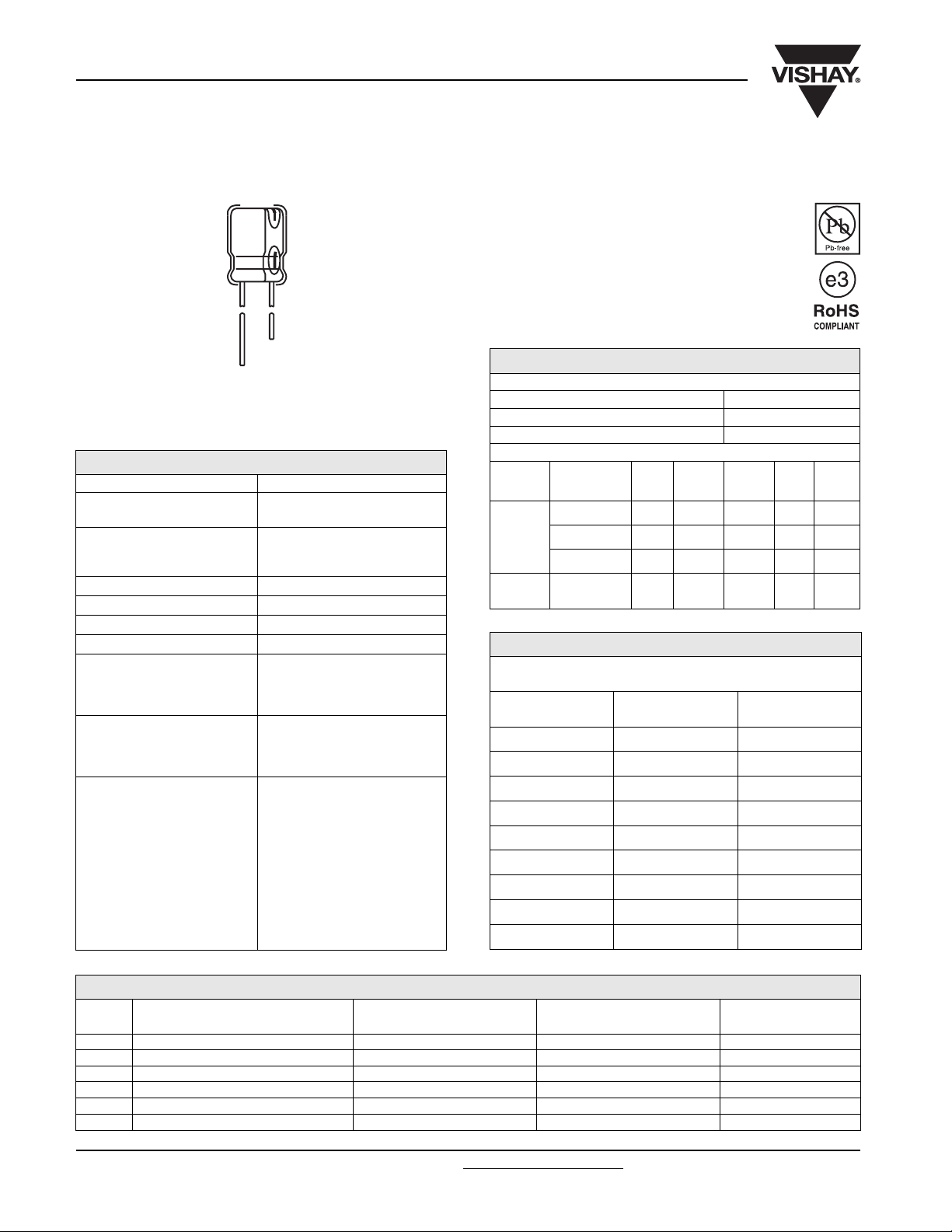
Fig.1 Component outline
QUICK REFERENCE DATA
DESCRIPTION VALUE
Nominal case size
Ø D x L in mm
Operating temperature
Rated Capacitance range, C
Tolerance on C
Rated voltage range, U
Termination 2 radial leads
Life validation test at 85 °C
Shelf life at 85 °C
DC leakage current
R
R
0.157” x 0.276” [4.0 x 7.0]
to 0.709” x 1.575” [18.0 x 40.0]
- 40 °C to + 85 °C
- 25 °C to + 85 °C for 315 WVDC
to 450 WVDC units
R
0.1 µF to 18 000 µF
± 20 %
6.3 WVDC to 450 WVDC
2000 hours: ΔCAP ± 20 % from
initial measurement.
ΔDF 2 x initial specified limit.
ΔDCL ≤ initial specified limit
1000 hours: ΔCAP ± 20 % from
initial measurement.
ΔDF 2 x initial specified limit.
ΔDCL ≤ initial specified limit
rated voltage for 1 and 2 minutes
for 6.3 WVDC to
100 WVDC units:
I < 0.03 CV or 4 µA
(whichever is greater).
I < 0.04 CV or 3 µA
(whichever is greater).
rated voltage for 1 minute for
160 WVDC to 450 WVDC units:
I < 0.1 CV + 40 µA and
CV
≤
1000; I < 0.04 CV + 100 µA
and CV > 1000
RIPPLE CURRENT MULTIPLIERS
TEMPERATURE
Ambient Temperature Multipliers
≤ + 70 °C 1.27
+ 85 °C 1.0
FREQUENCY (Hz)
WVDC Cap. (µF) 50 - 60 100 - 120 300 - 400 1 kHz≤ 10 kHz
0 - 47 0.75 1 1.35 1.57 2.00
6.3 - 100
160 - 450
100 - 470 0.80 1 1.23 1.34 1.50
1000 - 18 000 0.85 1 1.10 1.13 1.15
0.47 - 220 0.80 1 1.25 1.40 1.60
LOW TEMPERATURE PERFORMANCE
MAXIMUM IMPEDANCE RATIO Z
MAXIMUM AT 120 Hz
Rated Voltage
(WVDC)
6.3 4.0 10.0
10.0 3.0 8.0
16.0 2.0 6.0
25.0 2.0 4.0
35.0 - 100.0 2.0 3.0
160.0 - 200.0 3.0 4.0
250.0 3.0 6.0
315.0 - 400.0 6.0 -
450.0 15.0 -
Z - 25 °C/Z + 20 °C Z - 40 °C/Z + 20 °C
(T)/Z(+ 20 °C)
DIMENSIONS in inches [millimeters]
CASE
CODE
HW 0.157 x 0.276 [4.0 x 7.0] 0.059 [1.5] 0.018 [0.45] 0.20
JW 0.197 x 0.276 [5.0 x 7.0] 0.079 [2.0] 0.018 [0.45] 0.30
AW 0.248 x 0.276 [6.3 x 7.0] 0.098 [2.5] 0.018 [0.45] 0.40
JA 0.197 x 0.433 [5.0 x 11.0] 0.079 [2.0] 0.020 [0.50] 0.44
AA 0.248 x 0.433 [6.3 x 11.0] 0.098 [2.5] 0.020 [0.50] 0.60
BB 0.315 x 0.453 [8.0 x 11.5] 0.138 [3.5] 0.024 [0.60] 0.95
www.vishay.com For technical questions, contact: aluminumcaps4@vishay.com
394 Revision: 13-Jun-08
NOMINAL CASE SIZE
D x L
LEAD SPACING
S
NOMINAL LEAD DIAMETER
D
TYPICAL WEIGHT
(g)
Document Number: 42052
515D
Aluminum Capacitors
Vishay Sprague
+ 85 °C, Miniature, Radial Lead
DIMENSIONS in inches [millimeters]
CASE
CODE
CC 0.394 x 0.492 [10.0 x 12.5] 0.197 [5.0] 0.024 [0.60] 1.48
CD 0.394 x 0.630 [10.0 x 16.0] 0.197 [5.0] 0.024 [0.60] 1.75
CG 0.394 x 0.787 [10.0 x 20.0] 0.197 [5.0] 0.024 [0.60] 2.37
DG 0.492 x 0.787 [12.5 x 20.0] 0.197 [5.0] 0.024 [0.60] 3.73
DK 0.492 x 0.984 [12.5 x 25.0] 0.197 [5.0] 0.024 [0.60] 4.85
EK 0.630 x 0.984 [16.0 x 25.0] 0.295 [7.5] 0.031 [0.80] 7.08
EN 0.630 x 1.240 [16.0 x 31.5] 0.295 [7.5] 0.031 [0.80] 8.94
ER 0.630 x 1.398 [16.0 x 35.5] 0.295 [7.5] 0.031 [0.80] 10.50
FR 0.709 x 1.398 [18.0 x 35.5] 0.295 [7.5] 0.031 [0.80] 12.53
FV 0.709 x 1.575 [18.0 x 40.0] 0.295 [7.5] 0.031 [0.80] 15.71
NOMINAL CASE SIZE
D x L
LEAD SPACING
S
ELECTROLYTIC CAPACITOR WITH CUT OR FORMED LEADS in inches [millimeters]
Code F
Code S
0.177
X
[4.5]
0.197 ± 0.20
D
F*
Ø d**
[5.0 ± 0.5]
D
0.177
[4.5]
X
Ø d**
NOMINAL LEAD DIAMETER
0.197 ± 0.20
F*
[5.0 ± 0.5]
D
Code S
D
TYPICAL WEIGHT
0.177
[4.5]
Ø d**
(g)
0.197 ± 0.20
F*
[5.0 ± 0.5]
Code C
D
0.177
[4.5]
Ø d*
Code S
S
F
*
± 0.20
[0.5]
0.033 ± 0.006
[0.85 ± 0.15]
Code S
(4, 5, 6.3, 8)
DIMENSIONS in inches [millimeters]
FORMING
METHOD
Formed and Cut F
Cut C
Snap-in S
Note
Coding of cut or formed lead to be added to the end of type number in 15th position (with position 14 coded “6”).
* Formed lead. ** Lead thickness Ø d depends on capacitor specification. *** Lead protrusion at bottom of tape.
FORMED LEAD
CODE
DIMENSIONS
D L.S. P e*** X (Max.)
0.157 [4.0] 0.197 [5.0] 0.059 [1.5]
0.197 [5.0] 0.197 [5.0] 0.079 [2.0]
0.248 [6.3] 0.197 [5.0] 0.098 [2.5]
0.315 [8.0] 0.197 [5.0] 0.138 [3.5]
0.394 [10.0] 0.197 [5.0]
0.492 [12.5] 0.197 [5.0]
0.630 [16.0] 0.295 [7.5]
0.709 [18.0] 0.295 [7.5]
0.157 [4.0] 0.197 [5.0] 0.059 [1.5]
0.197 [5.0] 0.197 [5.0] 0.079 [2.0]
0.248 [6.3] 0.197 [5.0] 0.098 [2.5]
0.315 [8.0] 0.197 [5.0] 0.138 [3.5]
0.394 [10.0] 0.197 [5.0]
0.492 [12.5] 0.197 [5.0]
0.630 [16.0] 0.295 [7.5]
0.709 [18.0] 0.295 [7.5]
---
---
---
---
0.043 [1.1] 0.059 [1.5]
0.043 [1.1] 0.059 [1.5]
0.043 [1.1] 0.059 [1.5]
0.051 [1.3] 0.059 [1.5]
- 0.051 [1.3] -
- 0.051 [1.3] -
- 0.051 [1.3] -
- 0.051 [1.3] -
0.039 ± 0.008
[1.0 ± 0.2]
(10, 12.5, 16, 18)
- 0.059 [1.5]
- 0.059 [1.5]
- 0.098 [2.5]
- 0.098 [2.5]
Document Number: 42052 For technical questions, contact: aluminumcaps4@vishay.com
Revision: 13-Jun-08 395
www.vishay.com
515D
Vishay Sprague
Aluminum Capacitors
+ 85 °C, Miniature, Radial Lead
TAPED CAPACITORS FOR AUTOMATIC INSERTION SYSTEMS in inches [millimeters]
PACKAGING
14th AND 15th
DIGITS OF PN
Ammo Pack 8P Formed Lead
Note
The ammo pack code is to be added at the end of part number in the 14th and 15th position as 8P. To
tape and ammo, both positions 14 and 15 of the type number must be filled in with the proper codes.
LEAD CODE
(1)
Except 0.394 [10.0 mm] and 0.492 [12.5 mm] diameter have straight unformed leads.
TAPING SPECIFICATIONS in inches [millimeters]
Formed Lead Type
SPECIFICATION
LEAD STYLE
(1)
H
+-
LEADER
- 0.197 [5.0]
P
F
LEAD
SPACE
CAPACITOR SIZES AVAILABLE
0.157 x 0.276 - 0.492 x 0.787 [4.0 x 7.0 - 12.5 x 20.0]
CASE CODES HW, JW, AW, JA, AA, BB, CC, CD, DG
specify formed, cut or snap-in leads and for
K
H
0
WW
0
P
0
Ø d
D
0
t
DIMENSIONS in inches [millimeters]
CASE SIZE
(Diameter x Length)
ITEM
0.157 x 0.276
[4.0 x 7.0]
0.197 x 0.276
[5.0 x 7.0]
Ø d - Lead-wire Diameter 0.018 [0.45] 0.018 [0.45] 0.020 [0.5] 0.018 [0.45] 0.020 [0.5] 0.024 [0.6] 0.024 [0.6] 0.024 [0.6]
P - Pitch of Component 0.500 [12.7] 0.500 [12.7] 0.500 [12.7] 0.500 [12.7] 0.500 [12.7] 0.500 [12.7] 0.500 [12.7] 0.591 [15.0]
- Feed Hole Pitch
P
0
0.500 [12.7] 0.500 [12.7] 0.500 [12.7] 0.500 [12.7] 0.500 [12.7] 0.500 [12.7] 0.500 [12.7] 0.591 [15.0]
F - Lead-to-lead Distance 0.197 [5.0] 0.197 [5.0] 0.197 [5.0] 0.197 [5.0] 0.197 [5.0] 0.197 [5.0] 0.197 [5.0] 0.197 [5.0]
K - Clinch Height 0.059 [1.5] 0.059 [1.5] 0.098 [2.5] 0.059 [1.5] 0.098 [2.5] 0.157 [4.0] - -
H - Height of Component
H
- Lead-wire Clinch Height
0
0.689 [17.5] 0.689 [17.5] 0.728 [18.5] 0.689 [17.5] 0.728 [18.5] 0.787 [20.0] 0.728 [18.5] 0.630 [16.0]
0.630 [16.0] 0.630 [16.0] 0.630 [16.0] 0.630 [16.0] 0.630 [16.0] 0.630 [16.0] - -
W - Tape Width 0.709 [18.0] 0.709 [18.0] 0.709 [18.0] 0.709 [18.0] 0.709 [18.0] 0.709 [18.0] 0.709 [18.0] 0.709 [18.0]
- Hold Down Tape Width
W
0
D
- Feed Hole Diameter
0
0.512 [13.0] 0.512 [13.0] 0.512 [13.0] 0.512 [13.0] 0.512 [13.0] 0.512 [13.0] 0.512 [13.0] 0.512 [13.0]
0.157[4.0] 0.157[4.0] 0.157[4.0] 0.157[4.0] 0.157[4.0] 0.157[4.0] 0.157[4.0] ] 0.157[4.0]
t - Total Tape Thickness 0.157 [4.0] 0.157 [4.0] 0.157 [4.0] 0.157 [4.0] 0.157 [4.0] 0.157 [4.0] 0.157 [4.0] 0.157 [4.0]
FORMED LEAD TYPE STRAIGHT LEAD TYPE
0.197 x 0.433
[5.0 x 11.0]
0.248 x 0.276
[6.3 x 7.0]
0.248 x 0.433
[6.3 x 11.0]
0.315 x 0.453
[8.0 x 11.5]
0.394 [10.0]
(Dia.)
0.492 [12.5]
(Dia.)
www.vishay.com For technical questions, contact: aluminumcaps4@vishay.com
Document Number: 42052
396 Revision: 13-Jun-08
515D
Aluminum Capacitors
Vishay Sprague
+ 85 °C, Miniature, Radial Lead
ORDERING EXAMPLE
Electrolytic capacitor 515D series: 515D 107 M 6R3 JA 6 A E3
DESCRIPTION
CODE EXPLANATION
515D product type
107 capacitance value (100 µF)
M tolerance (M = ± 20 %)
6R3 voltage rating at 85 °C (6R3 = 6.3 V)
JA can size (see dimensions table)
6 packaging (bulk)
A lead style (uncut)
E3 RoHS compliant indicator
PACKING AND LEAD STYLES:
6A Bulk, uncut leads
6C Bulk, cut leads
6F Bulk; formed and cut leads
6S Bulk, snap-in leads
8P Ammopack (case codes HW, JW, AW, JA, AA, BB, CC, CD, CG, DG only)
ELECTRICAL DATA AND ORDERING INFORMATION
CAPACITANCE
(µF)
22.0 515D226M6R3JA6AE3 0.197 x 0.433 [5.0 x 11.0] 34.0 0.24
33.0 515D336M6R3JA6AE3 0.197 x 0.433 [5.0 x 11.0] 42.0 0.24
47.0 515D476M6R3JA6AE3 0.197 x 0.433 [5.0 x 11.0] 50.0 0.24
100.0 515D107M6R3JA6AE3 0.197 x 0.433 [5.0 x 11.0] 77.0 0.24
220.0 515D227M6R3AA6AE3 0.248 x 0.433 [6.3 x 11.0] 215.0 0.24
330.0 515D337M6R3AA6AE3 0.248 x 0.433 [6.3 x 11.0] 265.0 0.24
470.0 515D477M6R3BB6AE3 0.315 x 0.453 [8.0 x 11.5] 360.0 0.24
1000.0 515D108M6R3CC6AE3 0.394 x 0.492 [10.0 x 12.5] 570.0 0.24
2200.0 515D228M6R3DG6AE3 0.492 x 0.787 [12.5 x 20.0] 1050.0 0.24
3300.0 515D338M6R3DG6AE3 0.492 x0 .787 [12.5 x 20.0] 1250.0 0.24
4700.0 515D478M6R3EK6AE3 0.630 x 0.984 [16.0 x 25.0] 1700.0 0.24
6800.0 515D688M6R3EK6AE3 0.630 x 0.984 [16.0 x 25.0] 1900.0 0.24
10 000.0 515D109M6R3EN6AE3 0.630 x 1.240 [16.0 x 31.5] 2250.0 0.24
15 000.0 515D159M6R3FR6AE3 0.709 x 1.398 [18.0 x 35.5] 2680.0 0.24
18 000.0 515D189M6R3FV6AE3 0.709 x 1.575 [18.0 x 40.0] 2750.0 0.24
22.0 515D226M010JA6AE3 0.197 x0 .433 [5.0 x 11.0] 38.0 0.20
33.0 515D336M010JA6AE3 0.197 x 0.433 [5.0 x 11.0] 47.0 0.20
47.0 515D476M010JA6AE3 0.197 x 0.433 [5.0 x 11.0] 59.0 0.20
100.0 515D107M010JA6AE3 0.197 x 0.433 [5.0 x 11.0] 145.0 0.20
220.0 515D227M010AA6AE3 0.248 x 0.433 [6.3 x 11.0] 230.0 0.20
330.0 515D337M010BB6AE3 0.315 x 0.453 [8.0 x 11.5] 330.0 0.20
470.0 515D477M010BB6AE3 0.315 x 0.453 [8.0 x 11.5] 390.0 0.20
1000.0 515D108M010CD6AE3 0.394 x 0.630 [10.0 x 16.0] 630.0 0.20
2200.0 515D228M010DG6AE3 0.492 x .0787 [12.5 x 20.0] 1100.0 0.20
3300.0 515D338M010DK6AE3 0.492 x 0.984 [12.5 x 25.0] 1400.0 0.20
4700.0 515D478M010EK6AE3 0.630 x .0984 [16.0 x 25.0] 1800.0 0.20
6800.0 515D688M010EN6AE3 0.630 x 1.240 [16.0 x 31.5] 2150.0 0.20
10 000.0 515D109M010FR6AE3 0.709 x 1.398 [18.0 x 35.5] 2500.0 0.20
15 000.0 515D159M010FV6AE3 0.709 x 1.575 [18.0 x 40.0] 2720.0 0.20
Document Number: 42052 For technical questions, contact: aluminumcaps4@vishay.com
Revision: 13-Jun-08 397
PART NUMBER
6.3 WVDC at + 85 °C, SURGE = 8 V
10 WVDC at + 85 °C, SURGE = 13 V
NOMINAL CASE SIZE
D x L
MAX. RIPPLE
AT + 85 °C
120 Hz (mA)
MAX. DF
AT + 20 °C
120 Hz
www.vishay.com

515D
Vishay Sprague
Aluminum Capacitors
+ 85 °C, Miniature, Radial Lead
ELECTRICAL DATA AND ORDERING INFORMATION
CAPACITANCE
(µF)
10.0 515D106M016JA6AE3 0.197 x .433 [5.0 x 11.0] 28.0 0.16
22.0 515D226M016JA6AE3 0.197 x 0.433 [5.0 x 11.0] 44.0 0.16
33.0 515D336M016JA6AE3 0.197 x 0.433 [5.0 x 11.0] 57.0 0.16
47.0 515D476M016JA6AE3 0.197 x 0.433 [5.0 x 11.0] 168.0 0.16
100.0 515D107M016AA6AE3 0.248 x 0.433 [6.3 x 11.0] 175.0 0.16
220.0 515D227M016BB6AE3 0.315 x 0.453 [8.0 x 11.5] 300.0 0.16
330.0 515D337M016BB6AE3 0.315 x 0.453 [8.0 x 11.5] 360.0 0.16
470.0 515D477M016CC6AE3 0.394 x 0.492 [10.0 x 12.5] 470.0 0.16
1000.0 515D108M016CG6AE3 0.394 x 0.787 [10.0 x 20.0] 790.0 0.16
2200.0 515D228M016DK6AE3 0.492 x 0.984 [12.5 x 25.0] 1350.0 0.16
3300.0 515D338M016EK6AE3 0.630 x 0.984 [16.0 x 25.0] 1700.0 0.16
4700.0 515D478M016EN6AE3 0.630 x 1.240 [16.0 x 31.5] 2100.0 0.16
6800.0 515D688M016FR6AE3 0.709 x 1.398 [18.0 x 35.5] 2500.0 0.16
10 000.0 515D109M016FV6AE3 0.709 x 1.575 [18.0 x 40.0] 2640.0 0.16
4.7 515D475M025JA6AE3 0.197 x 0.433 [5.0 x 11.0] 30.0 0.14
10.0 515D106M025JA6AE3 0.197 x 0.433 [5.0 x 11.0] 33.0 0.14
22.0 515D226M025JA6AE3 0.197 x 0.433 [5.0 x 11.0] 51.0 0.14
33.0 515D336M025JA6AE3 0.197 x 0.433 [5.0 x 11.0] 63.0 0.14
47.0 515D476M025JA6AE3 0.197 x 0.433 [5.0 x 11.0] 115.0 0.14
100.0 515D107M025AA6AE3 0.248 x 0.433 [6.3 x 11.0] 185.0 0.14
220.0 515D227M025BB6AE3 0.315 x 0.453 [8.0 x 11.5] 320.0 0.14
330.0 515D337M025CC6AE3 0.394 x 0.492 [10.0 x 12.5] 420.0 0.14
470.0 515D477M025CD6AE3 0.394 x 0.630 [10.0 x 16.0] 540.0 0.14
1000.0 515D108M025DG6AE3 0.492 x 0.787 [12.5 x 20.0] 950.0 0.14
2200.0 515D228M025EK6AE3 0.630 x 0.984 [16.0 x 25.0] 1550.0 0.14
3300.0 515D338M025EN6AE3 0.630 x 1.240 [16.0 x 31.5] 1950.0 0.14
4700.0 515D478M025FR6AE3 0.709 x 1.398 [18.0 x 35.5] 2360.0 0.14
4.7 515D475M035JA6AE3 0.197 x 0.433 [5.0 x 11.0] 24.0 0.12
10.0 515D106M035JA6AE3 0.197 x 0.433 [5.0 x 11.0] 36.0 0.12
22.0 515D226M035JA6AE3 0.197 x 0.433 [5.0 x 11.0] 57.0 0.12
33.0 515D336M035JA6AE3 0.197 x 0.433 [5.0 x 11.0] 105.0 0.12
47.0 515D476M035AA6AE3 0.248 x 0.433 [6.3 x 11.0] 140.0 0.12
100.0 515D107M035BB6AE3 0.315 x 0.453 [8.0 x 11.5] 230.0 0.12
220.0 515D227M035CC6AE3 0.394 x 0.492 [10.0 x 12.5] 370.0 0.12
330.0 515D337M035CD6AE3 0.394 x 0.630 [10.0 x 16.0] 490.0 0.12
470.0 515D477M035CG6AE3 0.394 x 0.787 [10.0 x 20.0] 640.0 0.12
1000.0 515D108M035DK6AE3 0.492 x 0.984 [12.5 x 25.0] 1100.0 0.12
2200.0 515D228M035EN6AE3 0.630 x 1.240 [16.0 x 31.5] 1850.0 0.12
3300.0 515D338M035FR6AE3 0.709 x 1.382 [18.0 x 35.5] 2220.0 0.12
4700.0 515D478M035FV6AE3 0.709 x 1.575 [18.0 x 40.0] 2490.0 0.12
0.1 515D104M050JA6AE3 0.197 x 0.433 [5.0 x 11.0] 1.0 0.10
0.22 515D224M050JA6AE3 0.197 x 0.433 [5.0 x 11.0] 2.3 0.10
0.33 515D334M050JA6AE3 0.197 x 0.433 [5.0 x 11.0] 3.5 0.10
0.47 515D474M050JA6AE3 0.197 x 0.433 [5.0 x 11.0] 5.0 0.10
1.0 515D105M050JA6AE3 0.197 x 0.433 [5.0 x 11.0] 10.0 0.10
2.2 515D225M050JA6AE3 0.197 x 0.433 [5.0 x 11.0] 19.0 0.10
3.3 515D335M050JA6AE3 0.197 x 0.433 [5.0 x 11.0] 24.0 0.10
4.7 515D475M050JA6AE3 0.197 x 0.433 [5.0 x 11.0] 29.0 0.10
www.vishay.com For technical questions, contact: aluminumcaps4@vishay.com
398 Revision: 13-Jun-08
PART NUMBER
NOMINAL CASE SIZE
D x L
16 WVDC at + 85 °C, SURGE = 20 V
16 WVDC at + 85 °C, SURGE = 20 V
25 WVDC at + 85 °C, SURGE = 32 V
35 WVDC at + 85 °C, SURGE = 44 V
50 WVDC at + 85 °C, SURGE = 63 V
MAX. RIPPLE
AT + 85 °C
120 Hz (mA)
Document Number: 42052
MAX. DF
AT + 20 °C
120 Hz

515D
Aluminum Capacitors
Vishay Sprague
+ 85 °C, Miniature, Radial Lead
ELECTRICAL DATA AND ORDERING INFORMATION
CAPACITANCE
(µF)
10.0 515D106M050JA6AE3 0.197 x 0.433 [5.0 x 11.0] 44.0 0.10
22.0 515D226M050JA6AE3 0.197 x 0.433 [5.0 x 11.0] 95.0 0.10
33.0 515D336M050AA6AE3 0.248 x 0.433 [6.3 x 11.0] 125.0 0.10
47.0 515D476M050AA6AE3 0.248 x 0.433 [6.3 x 11.0] 150.0 0.10
100.0 515D107M050BB6AE3 0.315 x 0.453 [8.0 x 11.5] 250.0 0.10
220.0 515D227M050CD6AE3 0.394 x 0.630 [10.0 x 16.0] 440.0 0.10
330.0 515D337M050CG6AE3 0.394 x 0.787 [10.0 x 20.0] 580.0 0.10
470.0 515D477M050DG6AE3 0.492 x 0.787 [12.5 x 20.0] 760.0 0.10
1000.0 515D108M050EK6AE3 0.630 x 0.984 [16.0 x 25.0] 1350.0 0.10
2200.0 515D228M050FR6AE3 0.709 x 1.398 [18.0 x 35.5] 2090.0 0.10
4.7 515D475M063JA6AE3 0.197 x 0.433 [5.0 x 11.0] 45.0 0.08
10.0 515D106M063JA6AE3 0.197 x 0.433 [5.0 x 11.0] 70.0 0.08
22.0 515D226M063AA6AE3 0.248 x 0.433 [6.3 x 11.0] 115.0 0.08
33.0 515D336M063AA6AE3 0.248 x 0.433 [6.3 x 11.0] 140.0 0.08
47.0 515D476M063BB6AE3 0.315 x 0.453 [8.0 x 11.5] 190.0 0.08
100.0 515D107M063CC6AE3 0.394 x 0.492 [10.0 x 12.5] 300.0 0.08
220.0 515D227M063CG6AE3 0.394 x 0.787 [10.0 x 20.0] 490.0 0.08
330.0 515D337M063DG6AE3 0.492 x 0.787 [12.5 x 20.0] 680.0 0.08
470.0 515D477M063DK6AE3 0.492 x 0.984 [12.5 x 25.0] 880.0 0.08
1000.0 515D108M063EN6AE3 0.630 x 1.240 [16.0 x 31.5] 1550.0 0.08
2200.0 515D228M063FV6AE3 0.709 x 1.575 [18.0 x 40.0] 2200.0 0.08
0.1 515D104M100JA6AE3 0.197 x 0.433 [5.0 x 11.0] 2.1 0.08
0.22 515D224M100JA6AE3 0.197 x 0.433 [5.0 x 11.0] 4.7 0.08
0.33 515D334M100JA6AE3 0.197 x 0.433 [5.0 x 11.0] 7.0 0.08
0.47 515D474M100JA6AE3 0.197 x .0433 [5.0 x 11.0] 10.0 0.08
1.0 515D105M100JA6AE3 0.197 x 0.433 [5.0 x 11.0] 21.0 0.08
2.2 515D225M100JA6AE3 0.197 x 0.433 [5.0 x 11.0] 30.0 0.08
3.3 515D335M100JA6AE3 0.197 x 0.433 [5.0 x 11.0] 40.0 0.08
4.7 515D475M100JA6AE3 0.197 x 0.433 [5.0 x 11.0] 45.0 0.08
10.0 515D106M100AA6AE3 0.248 x 0.433 [6.3 x 11.0] 75.0 0.08
22.0 515D226M100BB6AE3 0.315 x 0.453 [8.0 x 11.5] 130.0 0.08
33.0 515D336M100CC6AE3 0.394 x 0.492 [10.0 x 12.5] 170.0 0.08
47.0 515D476M100CD6AE3 0.394 x 0.630 [10.0 x 16.0] 230.0 0.08
100.0 515D107M100DG6AE3 0.492 x 0.787 [12.5 x 20.0] 400.0 0.08
220.0 515D227M100EK6AE3 0.630 x 0.984 [16.0 x 25.0] 710.0 0.08
330.0 515D337M100EK6AE3 0.630 x 0.984 [16.0 x 25.0] 860.0 0.08
470.0 515D477M100EN6AE3 0.630 x 1.240 [16.0 x 31.5] 1100.0 0.08
1000.0 515D108M100FV6AE3 0.709 x 1.575 [18.0 x 40.0] 1690.0 0.08
0.47 515D474M160AA6AE3 0.248 x 0.433 [6.3 x 11.0] 12.0 0.20
1.0 515D105M160AA6AE3 0.248 x 0.433 [6.3 x 11.0] 17.0 0.20
2.2 515D225M160AA6AE3 0.248 x 0.433 [6.3 x 11.0] 26.0 0.20
3.3 515D335M160BB6AE3 0.315 x 0.453 [8.0 x 11.5] 35.0 0.20
4.7 515D475M160BB6AE3 0.315 x 0.453 [8.0 x 11.5] 40.0 0.20
10.0 515D106M160CC6AE3 0.394 x 0.492 [10.0 x 12.5] 65.0 0.20
22.0 515D226M160CG6AE3 0.394 x 0.787 [10.0 x 20.0] 110.0 0.20
33.0 515D336M160DG6AE3 0.492 x 0.787 [12.5 x 20.0] 150.0 0.20
47.0 515D476M160DK6AE3 0.492 x 0.984 [12.5 x 25.0] 180.0 0.20
100.0 515D107M160EK6AE3 0.630 x 0.984 [16.0 x 25.0] 300.0 0.20
220.0 515D227M160FR6AE3 0.709 x 1.398 [18.0 x 35.5] 510.0 0.20
Document Number: 42052 For technical questions, contact: aluminumcaps4@vishay.com
Revision: 13-Jun-08 399
PART NUMBER
NOMINAL CASE SIZE
D x L
50 WVDC at + 85 °C, SURGE = 63 V
63 WVDC at + 85 °C, SURGE = 79 V
100 WVDC at + 85 °C, SURGE = 125 V
160 WVDC at + 85 °C, SURGE = 200 V
MAX. RIPPLE
AT + 85 °C
120 Hz (mA)
MAX. DF
AT + 20 °C
120 Hz
www.vishay.com

515D
Vishay Sprague
Aluminum Capacitors
+ 85 °C, Miniature, Radial Lead
ELECTRICAL DATA AND ORDERING INFORMATION
CAPACITANCE
(µF)
0.47 515D474M200AA6AE3 0.248 x 0.433 [6.3 x 11.0] 12.0 0.20
1.0 515D105M200AA6AE3 0.248 x 0.433 [6.3 x 11.0] 17.0 0.20
2.2 515D225M200AA6AE3 0.248 x 0.433 [6.3 x 11.0] 26.0 0.20
3.3 515D335M200BB6AE3 0.315 x 0.453 [8.0 x 11.5] 35.0 0.20
4.7 515D475M200CC6AE3 0.394 x 0.492 [10.0 x 12.5] 45.0 0.20
10.0 515D106M200CD6AE3 0.394 x 0.630 [10.0 x 16.0] 70.0 0.20
22.0 515D226M200CG6AE3 0.394 x 0.787 [10.0 x 20.0] 110.0 0.20
33.0 515D336M200DK6AE3 0.492 x 0.984 [12.5 x 25.0] 160.0 0.20
47.0 515D476M200DK6AE3 0.492 x 0.984 [12.5 x 25.0] 180.0 0.20
100.0 515D107M200EN6AE3 0.630 x 1.240 [16.0 x 31.5] 330.0 0.20
220.0 515D227M200FV6AE3 0.709 x 1.575 [18.0 x 40.0] 520.0 0.20
0.47 515D474M250AA6AE3 0.248 x 0.433 [6.3 x 11.0] 12.0 0.20
1.0 515D105M250AA6AE3 0.248 x 0.433 [6.3 x 11.0] 17.0 0.20
2.2 515D225M250BB6AE3 0.315 x 0.453 [8.0 x 11.5] 30.0 0.20
3.3 515D335M250CC6AE3 0.394 x 0.492 [10.0 x 12.5] 35.0 0.20
4.7 515D475M250CC6AE3 0.394 x 0.492 [10.0 x 12.5] 45.0 0.20
10.0 515D106M250CG6AE3 0.394 x 0.787 [10.0 x 20.0] 70.0 0.20
33.0 515D336M250DK6AE3 0.492 x 0.984 [12.5 x 25.0] 160.0 0.20
47.0 515D476M250EK6AE3 0.630 x 1.240 [16.0 x 31.5] 210.0 0.20
100.0 515D107M250FR6AE3 0.709 x 1.575 [18.0 x 40.0] 340.0 0.20
1.0 515D105M315AA6AE3 0.248 x 0.433 [6.3 x 11.0] 17.0 0.20
2.2 515D225M315BB6AE3 0.315 x 0.453 [8.0 x 11.5] 30.0 0.20
3.3 515D335M315CC6AE3 0.394 x 0.492 [10.0 x 12.5] 35.0 0.20
4.7 515D475M315CD6AE3 0.394 x 0.630 [10.0 x 16.0] 45.0 0.20
10.0 515D106M315CG6AE3 0.394 x 0.787 [10.0 x 20.0] 70.0 0.20
22.0 515D226M315DK6AE3 0.492 x 0.984 [12.5 x 25.0] 120.0 0.20
33.0 515D336M315EK6AE3 0.630 x 0.984 [16.0 x 25.0] 150.0 0.20
47.0 515D476M315EN6AE3 0.630 x 1.240 [16.0 x 31.5] 190.0 0.20
100.0 515D107M315FV6AE3 0.709 x 1.575 [18.0 x 40.0] 340.0 0.20
1.0 515D105M350BB6AE3 0.315 x .453 [8.0 x 11.5] 18.0 0.25
2.2 515D225M350CC6AE3 0.394 x .492 [10.0 x 12.5] 28.0 0.25
3.3 515D335M350CD6AE3 0.394 x .630 [10.0 x 16.0] 35.0 0.25
4.7 515D475M350CD6AE3 0.394 x .630 [10.0 x 16.0] 40.0 0.25
10.0 515D106M350DG6AE3 0.492 x .787 [12.5 x 20.0] 70.0 0.25
22.0 515D226M350DK6AE3 0.492 x .984 [12.5 x 25.0] 110.0 0.25
33.0 515D336M350EN6AE3 0.630 x 1.240 [16.0 x 31.5] 140.0 0.25
47.0 515D476M350FR6AE3 0.709 x 1.398 [18.0 x 35.5] 220.0 0.25
1.0 515D105M400BB6AE3 0.315 x 0.453 [8.0 x 11.5] 18.0 0.25
2.2 515D225M400CC6AE3 0.394 x 0.492 [10.0 x 12.5] 28.0 0.25
3.3 515D335M400CD6AE3 0.394 x 0.630 [10.0 x 16.0] 35.0 0.25
4.7 515D475M400CD6AE3 0.394 x 0.787 [10.0 x 20.0] 45.0 0.25
10.0 515D106M400DG6AE3 0.492 x 0.787 [12.5 x 20.0] 70.0 0.25
22.0 515D226M400DK6AE3 0.630 x 0.984 [16.0 x 25.0] 110.0 0.25
33.0 515D336M400EN6AE3 0.630 x 1.240 [16.0 x 31.5] 140.0 0.25
47.0 515D476M400FR6AE3 0.709 x 1.398 [18.0 x 35.5] 220.0 0.25
PART NUMBER
NOMINAL CASE SIZE
D x L
200 WVDC at + 85 °C, SURGE = 250 V
250 WVDC at + 85 °C, SURGE = 300 V
315 WVDC at + 85 °C, SURGE = 365 V
350 WVDC at + 85 °C, SURGE = 400 V
400 WVDC at + 85 °C, SURGE = 450 V
MAX. RIPPLE
AT + 85 °C
120 Hz (mA)
MAX. DF
AT + 20 °C
120 Hz
www.vishay.com For technical questions, contact: aluminumcaps4@vishay.com
400 Revision: 13-Jun-08
Document Number: 42052

515D
Aluminum Capacitors
Vishay Sprague
+ 85 °C, Miniature, Radial Lead
ELECTRICAL DATA AND ORDERING INFORMATION
CAPACITANCE
(µF)
1.0 515D105M450CC6AE3 0.394 x 0.492 [10.0 x 12.5] 19.0 0.25
2.2 515D225M450CD6AE3 0.394 x 0.630 [10.0 x 16.0] 29.0 0.25
4.7 515D475M450DG6AE3 0.492 x 0.787 [12.5 x 20.0] 50.0 0.25
10.0 515D106M450EK6AE3 0.492 x 0.984 [12.5 x 25.0] 75.0 0.25
22.0 515D226M450EN6AE3 0.630 x 1.240 [16.0 x 31.5] 110.0 0.25
33.0 515D336M450FR6AE3 0.709 x 1.398 [18.0 x 35.5] 170.0 0.25
PART NUMBER
NOMINAL CASE SIZE
D x L
450 WVDC at + 85 °C, SURGE = 500 V
LOW PROFILE RATINGS in inches [millimeters]
CAPACITANCE
(µF)
22.0 515D226M6R3HW6AE3 0.157 x 0.276 [4.0 x 7.0] 34.0 0.24
33.0 515D336M6R3JW6AE3 0.197 x 0.276 [5.0 x 7.0] 42.0 0.24
47.0 515D476M6R3JW6AE3 0.197 x 0.276 [5.0 x 7.0] 50.0 0.24
100.0 515D107M6R3AW6AE3 0.248 x 0.276 [6.3 x 7.0] 77.0 0.24
22.0 515D226M010JW6AE3 0.197 x 0.276 [5.0 x 7.0] 38.0 0.20
33.0 515D336M010JW6AE3 0.197 x 0.276 [5.0 x 7.0] 47.0 0.20
47.0 515D476M010AW6AE3 0.248 x 0.276 [6.3 x 7.0] 59.0 0.20
10.0 515D106M016HW6AE3 0.157 x 0.276 [4.0 x 7.0] 28.0 0.16
22.0 515D226M016JW6AE3 0.197 x 0.276 [5.0 x 7.0] 44.0 0.16
33.0 515D336M016AW6AE3 0.248 x 0.276 [6.3 x 7.0] 57.0 0.16
47.0 515D476M016AW6AE3 0.248 x 0.276 [6.3 x 7.0] 68.0 0.16
10.0 515D106M025JW6AE3 0.197 x 0.276 [5.0 x 7.0] 33.0 0.14
22.0 515D226M025AW6AE3 0.248 x 0.276 [6.3 x 7.0] 51.0 0.14
33.0 515D336M025AW6AE3 0.248 x 0.276 [6.3 x 7.0] 63.0 0.14
4.7 515D475M035HW6AE3 0.157 x 0.276 [4.0 x 7.0] 24.0 0.12
10.0 515D106M035JW6AE3 0.197 x 0.276 [5.0 x 7.0] 36.0 0.12
22.0 515D226M035AW6AE3 0.248 x 0.276 [6.3 x 7.0] 57.0 0.12
0.1 515D104M050JW6AE3 0.157 x 0.276 [4.0 x 7.0] 1.0 0.10
0.22 515D224M050HW6AE3 0.157 x 0.276 [4.0 x 7.0] 2.3 0.10
0.33 515D334M050HW6AE3 0.157 x 0.276 [4.0 x 7.0] 3.5 0.10
0.47 515D474M050HW6AE3 0.157 x 0.276 [4.0 x 7.0] 5.0 0.10
1.0 515D105M050HW6AE3 0.157 x 0.276 [4.0 x 7.0] 10.0 0.10
2.2 515D225M050HW6AE3 0.157 x 0.276 [4.0 x 7.0] 19.0 0.10
3.3 515D335M050HW6AE3 0.157 x 0.276 [4.0 x 7.0] 24.0 0.10
4.7 515D475M050JW6AE3 0.197 x 0.276 [5.0 x 7.0] 29.0 0.10
10.0 515D106M050AW6AE3 0.248 x 0.276 [6.3 x 7.0] 44.0 0.10
PART NUMBER
NOMINAL CASE SIZE
D x L
6.3 WVDC at + 85 °C, SURGE = 8 V
10 WVDC at + 85 °C, SURGE = 13 V
16 WVDC at + 85 °C, SURGE = 20 V
25 WVDC at + 85 °C, SURGE = 32 V
35 WVDC at + 85 °C, SURGE = 44 V
50 WVDC at + 85 °C, SURGE = 63 V
MAX. RIPPLE
AT + 85 °C
120 Hz (mA)
MAX. RIPPLE
AT + 85 °C
120 Hz (mA)
MAX. DF
AT + 20 °C
120 Hz
MAX. DF
AT + 20 °C
120 Hz
Document Number: 42052 For technical questions, contact: aluminumcaps4@vishay.com
Revision: 13-Jun-08 401
www.vishay.com

Legal Disclaimer Notice
Vishay
Disclaimer
All product specifications and data are subject to change without notice.
Vishay Intertechnology, Inc., its affiliates, agents, and employees, and all persons acting on its or their behalf
(collectively, “Vishay”), disclaim any and all liability for any errors, inaccuracies or incompleteness contained herein
or in any other disclosure relating to any product.
Vishay disclaims any and all liability arising out of the use or application of any product described herein or of any
information provided herein to the maximum extent permitted by law. The product specifications do not expand or
otherwise modify Vishay’s terms and conditions of purchase, including but not limited to the warranty expressed
therein, which apply to these products.
No license, express or implied, by estoppel or otherwise, to any intellectual property rights is granted by this
document or by any conduct of Vishay.
The products shown herein are not designed for use in medical, life-saving, or life-sustaining applications unless
otherwise expressly indicated. Customers using or selling Vishay products not expressly indicated for use in such
applications do so entirely at their own risk and agree to fully indemnify Vishay for any damages arising or resulting
from such use or sale. Please contact authorized Vishay personnel to obtain written terms and conditions regarding
products designed for such applications.
Product names and markings noted herein may be trademarks of their respective owners.
Document Number: 91000 www.vishay.com
Revision: 18-Jul-08 1
 Loading...