

Page 1

WEIGH SYSTEM
TECHNOLOGY
BLH
DXp-40
Interface Manual
Allen-Bradley Remote I/O
TM014
Rev D
6/1/11
Doc 35105
Page 2

NOTICE
BLH makes no representation or warranties of any kind whatsoever with respect to the contents hereof
and specifically disclaims any implied warranties or merchantability or fitness for any particular purpose.
BLH shall not be held liable for errors contained herein or for incidental or consequential damages in
connection with the furnishing, performance, or use of this publication or its contents.
BLH reserves the right to revise this manual at any time and to make changes in the contents hereof
without obligation to notify any person of such revision or changes.
Call (781) 298-2216 for BLH Field Service
Page 3

Table of Contents
SECTION 1. Introduction ..................................................................................................................... 1-1
1.1 RIO OVERVIEW
1.2 THE DXp-40 WEIGHT TRANSMITTER
1.3 ALLEN-BRADLEY PLC-5 PROGRAMMABLE CONTROLLER ................................................. 1-1
1.4 FIELD ENGINEERING
SECTION 2. The Remote I/O Interface ............................................................................................... 2-3
2.1 OPERATIONAL OVERVIEW
2.2 HARDWARE CONFIGURATIONS
2.3 DISCRETE DATA TRANSFER .................................................................................................. 2-5
2.3.1 Output Image Table ............................................................................................................... 2-5
2.4 BLOCK DATA TRANSFERS ...................................................................................................... 2-7
2.4.1 Interface Basics ...................................................................................................................... 2-7
2.4.2 Transfer Reads (BTRs) .......................................................................................................... 2-7
2.4.3 Block Transfer Writes (13-1111s) ........................................................................................... 2-7
2.4.4 A Perpetual Pointer ................................................................................................................ 2-7
2.4.5 Fault Evaluation...................................................................................................................... 2-7
2.4.6 Remote Filter Configuration ................................................................................................... 2-7
....................................................................................................................... 1-1
.................................................................................. 1-1
............................................................................................................. 1-1
................................................................................................... 2-3
.......................................................................................... 2-3
SECTION 3. Definitions and Explanations .......................................................................................... 3-1
3.1
INPUT IMAGE TABLE BITS ...................................................................................................... 3-1
3.2 OUTPUT
SECTION 4. Sample Ladder Logic Programs
4.1 INTRODUCTION ........................................................................................................................ 4-1
4.1.1 Scale Training Program ......................................................................................................... 4-1
4.1.2 ata Reads, Writes, and Transfers .......................................................................................... 4-1
4.1.3 Reference Tables ................................................................................................................... 4-1
4.2 SAMPLE PROGRAM AVAILABI LITY ....................................................................................... 4-1
4.2.1 Sample Program Disclaimer .................................................................................................. 4-1
Appendix A - Wiring Diagram
Trademark Usage Acknowledgment
Allen-Bradley, ENABLED, and PLC are trademarks of Allen-Bradley Company, Inc.
IMAGE
TABLE BITS
................................................................................................. 3-2
.................................................................................. 4-1
Page 4

SECTION 1. Introduction
This manual describes an Allen-Bradley Remote I/O
(RIO) communication link between a BLH DXp-40
weight transmitter and an Allen-Bradley PLC-5 (Figure
1-1). This interface method uses technologies licensed
by BLH from Allen-Bradley. Functionally this digital
communication method provides a simple method of
transferring various type of weight data, status and
diagnostic information as well as the retrieval and
download of filter and other set-up parameters. Refer
to the standard DXp-40 manual, TM008, for DXp-40
operating procedures and parameter definitions.
1.1 RIO OVERVIEW
The Allen-Bradley Remote I/O (RIO) interface is a
communications link that supports remote, time critical
VO control communications between a master
processor and a remote I10 slave. It is typically used to
transfer I/O bit images between the master and slave.
The DXp-40 represents a quarter (1/4) Rack of
discrete I/O with 32 bits of input and output image files
to the scanning PLC. All weight data and status
information uses discrete reads and writes to
communicate scale information to the PLC in the
shortest time possible. Block transfers are used to
upload and download non-time critical information such
as diagnostic, status, and individual load cell data.
1.2 THE DXp-40 WEIGHT TRANSMITTER
The DXp-40 is a high performance weight transmitter
with features that make it suitable for both inventory
and process weighing applications. The transmitter
includes individual analog to digital conversion
channels for up to four load cells, microprocessor
based electronics to digitize the load cell signals, and a
serial RS-485 or Allen-Bradley Remote I/O
communication port. For field mount applications,
standard units are housed in a NEMA 4 epoxy painted
steel enclosure.
Optionally the DXp-40 is available with on-line
diagnostics, digital calibration, and Dynamic Digital
Filtering. Units also are available with Factory Mutual
Approval for installation in a Class I, II, III Division 2
hazardous locations.
Set-up and calibration procedures are accomplished
using a series of internal switches and the LCD display
(reference TM008). In operation, it provides up to three
million counts of weight resolution at an update rate of
50 milliseconds.
1.3 ALLEN-BRADLEY PLC-5 PROGRAMMABLE
CONTROLLER
The Allen Bradley PLC-5 series of mid-size
programmable controllers are used as part of
distributed process automation architecture. A variety
of 1771 series racks and I/O modules are available for
local or remote discrete and analog process control.
The PLC-5 can digitally communicate to other devices
using a conventional RS 232 or 423 serial port in
addition to special interface ports such as Data
Highway Plus, Scanner Communications, and Remote
I/O Adapter.
1.4 FIELD ENGINEERING
BLH will not accept any liability for faulty installation
and/or misuse of this product. Authorized BLH Field
Service Engineers are available around the world to
install DXp-40 transmitters and/or train factory
personnel to do so. The field service department at
BLH is the most important tool to assure the best performance from your application. Field service phone
numbers are listed below.
Notice: BLH makes no representation or warranties of
any kind whatsoever with respect to the contents
hereof and specifically disclaims any implied
warranties or merchantability or fitness for any
particular purpose. BLH shall not be held liable for
errors contained herein or for incidental or consequential damages in connection with the furnishing,
performance, or use of this publication or its contents.
BLH reserves the right to revise this manual at any
time and to make changes in the contents hereof
without obligation to notify any person of such revision
or changes.
1-1
Page 5
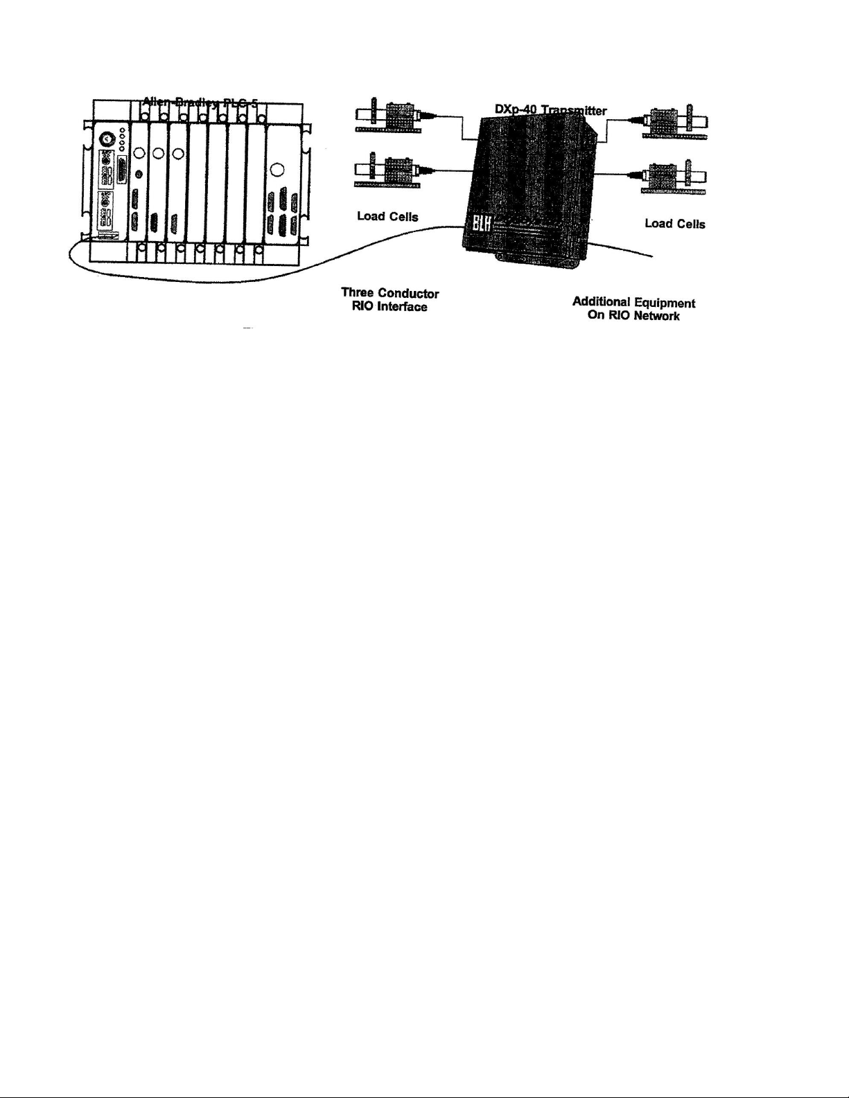
Figure 1-1. Allen-Bradley Remote I/O Network Interface
1-2
Page 6
SECTION 2. The Remote I/O Interface
2.1 OPERATIONAL OVERVIEW
The Allen-Bradley Remote I/O (RIO) interface is
standard on many PLC-2, 3, and 5 series
programmable logic controllers. The technology
used in the interface and licensed by Allen-Bradley
to BLH enables the DXp-40 transmitter to
communicate weight information to the PLC as if it
were a 1/4 rack of discrete I/O. By using the
standard RIO interface port and representing
weight data as simple discrete I/O, a low cost
reliable communication link between the PLC and
weigh system is established. Standard PLC ladder
logic instructions convert binary weight data to an
integer or floating point weight value without
special software drivers and scan delays that occur
when data block transfers are used. The DXp-40
also communicates status information, diagnostics,
and calibration data to the PLC.
CONFIGURATIONS:
Figure 2-1. RIO Communication DIP Switch
Settings
One Quarter Rack. The DXp-40 is configured to
act as 1/4 rack of I/O using 2 input words and 2
output words in the PLC's I/O image table. DXp-40
addressing supports racks 1-32. Four DXp-40s
constitute 1 full rack, each using a different starting
quarter. Discrete Transfer, Weight data and operating
status information transmitted through discrete
transfer using the PLC's Remote I10 image table.
Block Transfer, Block data transfers are initiated by
the PLC ladder logic program to obtain more in
depth status, diagnostic, and individual load cell
data.
Word Integrity Is Ensured. The DXp-40 will always
transmit both input image table words intact. To
ensure word integrity on the PLC side, immediate
writes to the output image table should be written
low word first.
2.2 HARDWARE CONFIGURATIONS
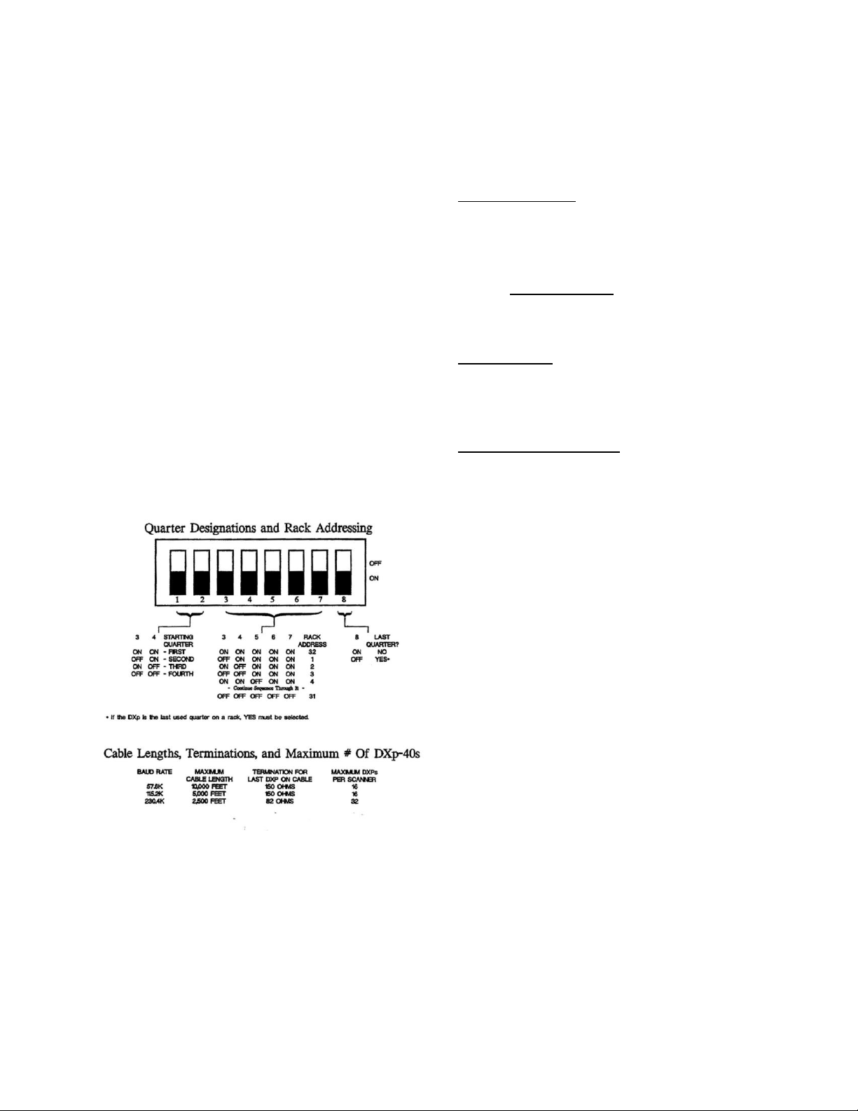
Rack address and starting quarter designations are
all configured using a row of DIP switches in the
DXp-40 (Figure 2-1). The DXp-40 is able to be
addressed up to rack number 32. Whenever the
DIP switch settings are changed, the unit must be
reset to allow the processor to read the new switch
settings.
RIO interface baud rate selections are available
through the DXp-40 main menu (Figure 2-2).
Recommended cable lengths are presented in
Figure 2-1.
2-3
Page 7
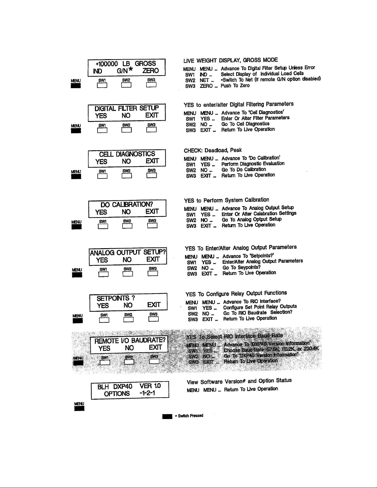
Main Menu (Accessed from Operation Mode)
Figure 2-2. Revised DXp-40 Main Menu w/Baud Rate Selection
2-4
Page 8
2.3 DISCRETE DATA TRANSFER
2.3.1 OUTPUT IMAGE TABLE
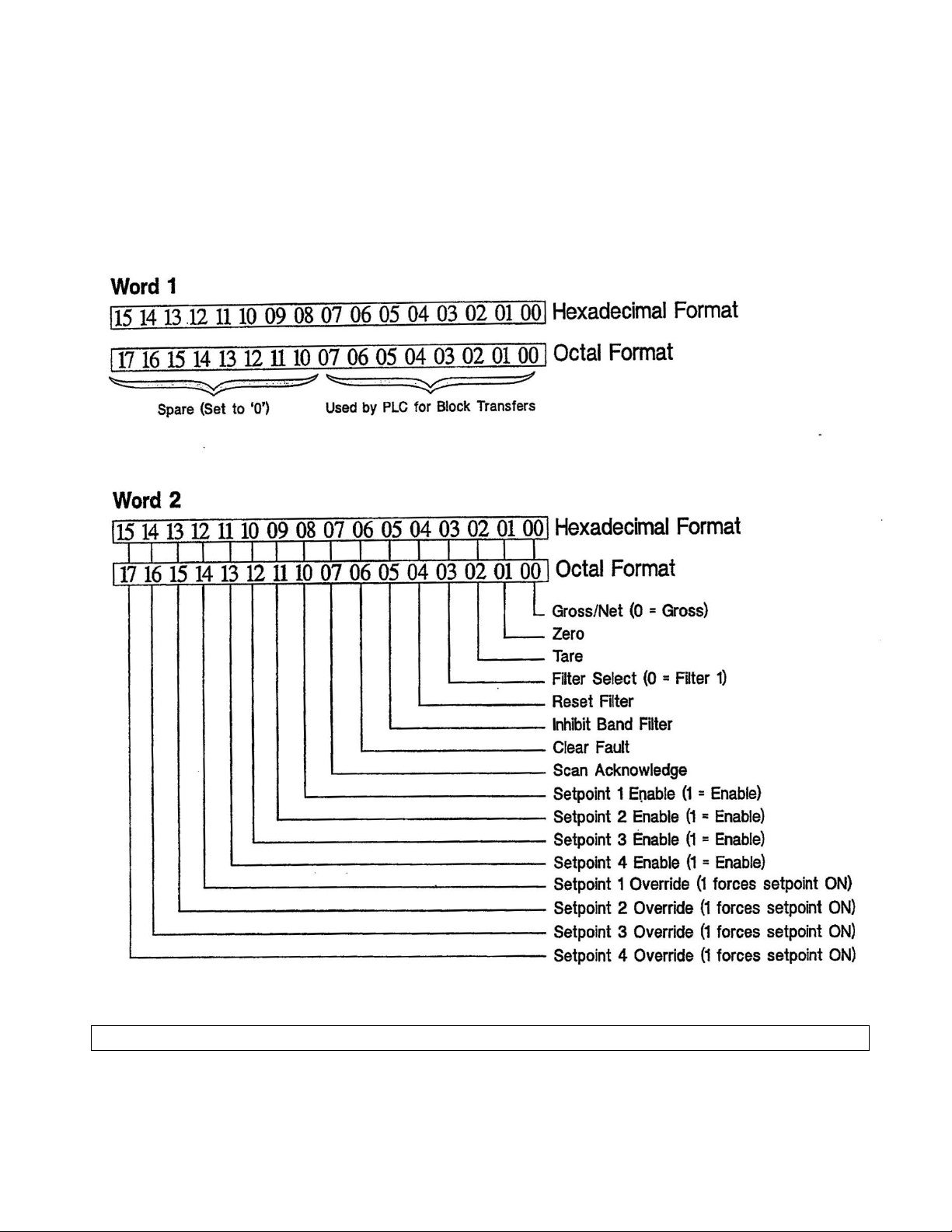
The PLC-5 initiates the communication interface by
transmitting two words from the output image table
(Figure 2-3). The first word is regarded as a 'spare'
by the DXp-40.
The second word contains the commands that the
PLC-5 expects the DXp-40 to perform. Word 2
controls set points, filter selection, filter operation,
and DXp-40 operating mode status.
Figure 2-3. The Output Image Table
NOTE: Octal and hexadecimal address formats are shown to cover PLC-5 and SLC-500 devices
2-5
Page 9
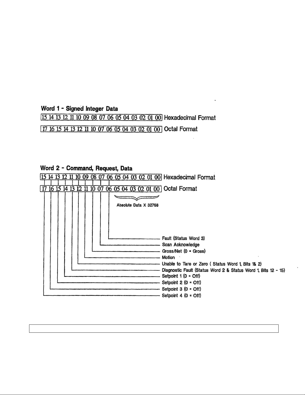
2.3.2 Input Image Table
After evaluating the contents of the output
image table, the DXp-40 responds by
transmitting two words to the input image
table (Figure 2-4). The first word contains
signed integer weight data. The second word
contains the upper order data bits, system
status, error condition, and set point status
information.
Figure 2-4. The Input Image Table
NOTE: Octal and hexadecimal address formats are shown to cover PLC-5 and SLC-500 devices
2-6
Page 10

2.4 BLOCK DATA TRANSFERS
2.4.1 INTERFACE BASICS
Block data transfers are initiated by the ladder
logic program write (BTW) and read (BTR)
commands. The transfer sequence begins when
the PLC sends the DXp40 a one word (16 bit
integer) write command containing a register
location pointer. This pointer is the 16 bit integer
value of the first register the PLC wishes to read
(factory default upon shipment is register 1).
Table 2-1 presents all available single and
double word register locations. After establishing
the starting register location, the PLC then
transmits a read transfer block command telling
the DXp--40 how many words of information are
needed.
and the second word being the new set point
value. Parameter guidelines for writing data to
the DXp-40 are presented in Table 2-2.
2.4.4 A PERPETUAL POINTER
One advantage to DXp-40 block transfers is that
the register pointer is retained in DXp-40
EEPROM. When a write block selects (points to)
a register location, that location may be
accessed (read) repeatedly without having to rewrite the register location word. Of course the
register pointer can be changed as often as
needed, but the last written location will always
be remembered, even during power down. This
feature saves a lot of BTWs when the PLC is
monitoring a particular register or block of
registers over a period of time.
2.4.2 TRANSFER READS (BTRS)
Once
the register location pointer value is
established, the PLC logic program must issue a
block transfer read command to obtain DXp-40
information. A BTR can request up to 64 words
of DXp-40 information (see Table 2-1). The
DXp-40 will respond to the BTR by transmitting
the number of words requested, starting at the
pointer location. NOTE: The first word
transmitted by the DXp-40 will be the register
pointer value. The DXp-40 adds this word at the
beginning of the transmission to 'echo' the
pointer value prior to transmitting requested
data. Therefore, the BTR command MUST add
1 to the number of words requested. If the PLC
needs four words of DXP information, the BTR
request must be for five words (Figure 2-5).
2.4.3 BLOCK TRANSFER WRITES (13
1111S)
Some of the DXp-40 registers may be written to
by the PLC (indicated by an '" in table 2-1). This
allows parameters such as filter, set point, and
diagnostic values to be down loaded on-the-fly
by the PLC ladder logic program. When writing
to the DXp-40, the first word must be the register
location pointer. Therefore, the program MUST
always add 1 to the BTW command length
(Figure 2-6). For example, to change a set point
value, the BTW length must equal 2 with the first
word being the set point register location pointer
2.4.5 FAULT EVALUATION
Three status words, register locations 1, 2, and
3, provide detailed explanations of error
conditions encountered by the DXp. When a
fault is detected, either bit 6 (fault) or bit 11
(diagnostic fault) in word 2 of the input image table is set to a '1' to alert the PLC of an error
condition. The PLC must then perform a BTR of
the appropriate status register to evaluate and
correct the error. If bit six (fault) is set, check
status word 3 for the error explanation. If bit 11
(diagnostic fault) is active, check status word 2
and status word 1 bits 12 - 15 for the error
explanation. Table 2-3 gives the status word bit
definitions.
2.4.6 REMOTE FILTER CONFIGURATION
DXp-40 transmitters equipped with the optional
-
Dynamic Digital Filter can be instructed by the
PLC to change filter settings on-the-fly. This
unique feature allows optimal, pre-determined
filtering parameters to be implemented at critical
moments during a dynamic weigh process.
Changing filter parameters throughout the
process ensures data stability and maximum
system response to actual weight changes.
Filter parameters are stored at register locations
59-70 (Table 2-1). Table 2-2 defines the filter
parameters that can be written to these registers
in the DXp-40. Request BLH technical note TD071 for a detailed description of Dynamic Digital
Filtering.
2-7
Page 11

WORD 1
WORD
2
WORD
3
WORD
4
WORD
5
Register
Address
4
Gross
Weight
Cell 1
Gross
Weight
Cell 2
Gross
Weight
Cell 3
Gross
Weight
Cell 4
WORD 1
WORD 2
Register
Address 55
Set Point
Value
Block Transfer Write Sample: One word desired
Table 2-1. Single & Double Word Register Pointer Locations
Single Word Registers Double Word Registers
01
STATUS 3
100 GROSS TOTAL
02
STATUS 2
102 GROSS CELL 1
03
STATUS 1
104 GROSS CELL 2
04
GROSS CELL 1
106 GROSS CELL 3
05
GROSS CELL 2
108 GROSS CELL 4
06
GROSS CELL 3
110 NET TOTAL
07
GROSS CELL 4
112 NET CELL 1
08
NET CELL 1
114 NET CELL 2
09
NET CELL 2
116 NET CELL 3
10
NET CELL 3
118 NET CELL 4
11
NET CELL 4
120 MV/V CELL 1
12
MV/V/10 CELL 3
122 MV/V CELL 2
13
MV/V/10 CELL 2
124 MV/V CELL 3
14
MV/V/10 CELL 3
126 RAVN CELL 4
15
MV/V/10 CELL 4
128 PEAK TOTAL
16
% LOAD CELL 1
130 PEAK CELL 1
17
% LOAD CELL 2
132 PEAK CELL 2
18
% LOAD CELL 3
134 PEAK CELL 3
19
% LOAD CELL 4
136 PEAK CELL 4
20
PEAK TOTAL
138 TARE
21
PEAK CELL 1
140 TARE CELL 1
22
PEAK CELL 2
142 TARE CELL 2
23
PEAK CELL 3
144 TARE CELL 3
24
PEAK CELL 4
146 TARE CELL 4
25
TARE 148 ZERO
26
TARE CELL 1
150 ZERO CELL 1
27
TARE CELL 2
152 ZERO CELL 2
28
TARE CELL 3
154 ZERO CELL 3
29
TARE CELL 4
156 ZERO CELL 4
30
ZERO 158* SETPOINT 1
31
ZERO CELL 1
160* SETPOINT 2
32
ZERO CELL 2
162* SETPOINT 3
33
ZERO CELL 3
164* SETPOINT 4
34
ZERO CELL 4
166* OVERLOAD CELL 1
35
% SENSITIVITY CELL 1
168* OVERLOAD CELL 2
36
% SENSITIVITY CELL 2
170* OVERLOAD CELL 3
37
% SENSITIVITY CELL 3
172* OVERLOAD CELL 4
38
V. SENSITIVITY CELL 4
39
1 LOAD SHIFT CELL 1
40
% LOAD SHIFT CELL 2
41
1 LOAD SHIFT CELL 3
* Word(s) can be written to by PLC
42
1 LOAD SHIFT CELL 4
43
POS DRIFT CELL 1
44
POS DRIFT CELL 2
45
POS DRIFT CELL 3
46
POS DRIFT CELL 4
47
MEG DRIFT CELL 1
48
NEG DRIFT CELL 2
49
NEG DRIFT CELL 3
50
NEG DRIFT CELL 4 NOISE CELL 1
Table 2-1 Notes:
52
NOISE CELL 2
53
NOISE CELL 3
1).Single word register integer data = -32768 to + 32767
54
NOISE CELL 4
55*
56*
SETPOINT 1
SETPOINT 2
2). Double word integer data must be converted to floating point using the
following equation:
(set point#1 weight value) requires two word write
command (1st word is set point #1 address).
Figure 2.5. Block Transfer Read
Figure 2-6. Block Transfer Write (BTW)
Sample
2-8
Page 12

57*
SETPOINT 3
58*
SETPOINT 4
59*
FILTER 1 LENGTH
((word 2) x 32768.0) + word 1
60*
FILTER 1 BAND
61*
FILTER 1 RESPONSE
range = -9,999,999 to 9,999,999
62*
FILTER 1 BAND AVERAGE
63*
FILTER 1 MOTION
64*
FILTER 1 MOTION TIMER
65*
FILTER 2 LENGTH
66*
FILTER 2 BAND
67*
FILTER 2 RESPONSE
68*
FILTER 2 BAND AVERAGE
69*
FILTER 2 MOTION
70*
FILTER 2 MOTION TIMER
71*
DIAG SHIFT UMIT
72*
DIAG ZERO SHIFT UMIT
73*
DIAG DRIFT UMIT
74*
DLAG NOISE UMIT
75*
OVERLOAD CELL 1
76*
OVERLOAD CELL 2
77*
OVERLOAD CELL 3
78*
OVERLOAD CELL 4
Table 2-2. Block Transfer Write Parameters
Diagnostic Entries
Diagnostic Shift Limit
Zero Shift Limit
Drift Limit
Noise Limit
Filter Parameter Entries
Filter Length
0 to 99 (0% to 99%)
0 to
9,999,999
0 to 99
counts* 0 to
99 counts
Motion
Motion Timer
00 =
50ms
00 = 2 00 = OFF
00
=
1/2 sec
01
=
100 ms
01 = 4
01
=
1 count
01
=
1 sec
02
=
200 ms
02 = 8
02
=
2 counts
02
=
2 sec
03
=
400 ms
03 = 16
03
=
3 counts
03
=
3 sec
04
=
800 ms
04 = 32
04
=
5 counts
05
=
1600 ms
05 = 64
05
=
10 counts
06
=
3200 ms
06 = 128
06
=
20 counts
07
=
6400 ms
07 = 256
07
=
50 counts
Set Point Entries - 0 to 9,999,999
Band Filter - 0 to 250 counts
Filter Response - 0 to 250 counts
Overload - 0 to 9,999,999
* Counts refers to displayed counts. If displayed weight is counting by 2 lb increments, then a selection of
nine counts will equal 18 lb.
NOTE: Refer to the standard DXp-40 manual, TM008, for DXp-40 parameter definitions.
2-9
Page 13

Table 2-3. Status Word Bit Definitions
STATUS 1 (GENERAL STATUS)
BIT 0 ACTIVE FILTER, (0) = FILTER 1, (1) = FILTER 2
BIT 1 UNABLE TO TARE/ZERO BECAUSE OF MOTION
BIT 2 UNABLE TO ZERO BECAUSE OF LIMIT
BIT 3 GROSS ZERO JUST ACQUIRED
BIT 4 NET TARE JUST ACQUIRED
BIT 5 IN CAL
BIT 6 SPARE
BIT 7 SPARE
BIT 8 INPUT 1
BIT 9 INPUT 2
BIT 10 INPUT 3
BIT 11 INPUT 4
BIT 12 OVERLOAD LIMIT CELL 1
BIT 13 OVERLOAD LIMIT CELL 2
BIT 14 OVERLOAD LIMIT CELL 3
BIT 15 OVERLOAD LIMIT CELL 4
STATUS 2 (DIAGNOSTIC ERRORS)
BIT 0 LOAD SHIFT CELL 1
BIT 1 LOAD SHIFT CELL 2
BIT 2 LOAD SHIFT CELL 3
BIT 3 LOAD SHIFT CELL 4
BIT 4 ZERO SHIFT CELL 1
BIT 5 ZERO SHIFT CELL 2
BIT 6 ZERO SHIFT CELL 3
BIT 7 ZERO SHIFT CELL 4
BIT 8 DRIFT CELL 1
BIT 9 DRIFT CELL 2
BIT 10 DRIFT CELL 3
BIT 11 DRIFT CELL 4
BIT 12 NOISE CELL 1
BIT 13 NOISE CELL 2
BIT 14 NOISE CELL 3
BIT 15 NOISE CELL 4
STATUS 3 (FAULTS)
BIT 0 POWERUP
BIT 1 2EEPROM CODE ERROR - DEFAULT DATA OVERLOAD
BIT 2 EEPROM READ ERROR
BIT 3 EEPROM WRITE ERROR
BIT 4 LOST ZERO
BIT 5 LOST TARE
BIT 6
BIT 7
BIT 8 A/D UNDERLOAD1 CELL 1
BIT 9 A/D OVERLOAD2 CELL 1
BIT 10 A/D UNDERLOAD CELL 2
BIT 11 A/D OVERLOAD CELL 2
BIT 12 A/D UNDERLOAD CELL 3
BIT 13 /D OVERLOAD CELL 3
BIT 14 A/D UNDERLOAD CELL 4
BIT 15 A/D OVERLOAD CELL 4
1 Underload = input signal too low
2 Overload = input signal too high
2-10
Page 14

SECTION 3. Definitions and Explanations
3.1
INPUT IMAGE TABLE BITS
A table is provided to explain the Input Image
Table presented in Figure 2-4. Table 3-1
defines the bit structure of both input words.
Word 1 BITS 0 - 15 WEIGH DATA (signed integer, -32768 to + 32767)
Signed integer.
Word 2
BITS 0 - 5 ABSOLUTE OVERFLOW DATA x 32768
Word 2 bits 0-5 is absolute overflow data from word 1 used if absolute weigh data is greater than 32,767. These 5 bits are
combined with the word 1 integer in a floating point register by the following steps.
1. Do a Masked move of Word 2 bits 0- 5 to an integer register.
2. Multiply the integer register by 32768.0 and put the result in a floating point register.
3. Negate the floating point result if the word 1 integer is negative.
4. Add the word 1 integer to the floating point result.
BIT 6 FAULT
Is set if there is a fault causing weigh data to be incorrect. This bit is cleared or suppressed by setting the clear fault bit in word 2 of
the output image table.
Table 3-1. Input Image Table Word 'Bit' Definitions
BIT 7 SCAN ACKNOWLEDGE
This bit is a copy of the same bit in the output Image table. When the D440 receives the output image table data it copies this bit to
the same location in the input image table. The plc can thus know if the remote I/O DXp40 has received the last write to the output
image table.
BIT 8 G/N, GROSS/NET DATA ID.
If this bit = 0 the weigh data in word 1 and bits 0-5 of word 2 is gross data. If this bit = 1 the weigh data is net weigh data.
BIT 9 MOTION
Is set If the weigh data is in motion as determined by the motion settings.
BIT 10 UNABLE TO TARE OR ZERO
Is set if the dxp40 is unable to tare or zero the data after receiving a zero or tare command from bits 1 or 2 of word 2 of the output
image table. The reasons for not being able to zero of tare are found in status #1 register bits 1 8, 2. This status register is
accessible through a block transfer read.
BIT 11 DIAGNOSTIC FAULT
Is set if any of the diagnostic fault bits are satin the status #1 register bits 12 -15 or status #2 register bits 0 -15. These status registers are accessible through a block transfer read.
BIT 12 SETPOINT #1
Is set if setpoint #1 output is on. If word 2 bit 8 of the output image table = 1 the setpoint #1 output is controlled by the dxp40. ff
word 2 bit 8 of the output image table = 0 the setpoint #1 output is controlled by word 2 bit 12 of the output image table.
BIT 13 SETPOINT # 2
Is set if setpoint #2 output is on. If word 2 bit 9 of the output image table = 1 the setpoint #2 output is controlled by the dxp40. If
word 2 bit 9 of the output image table = 0 the setpoint #2 output is controlled by word 2 bit 13 of the output image table.
BIT 14 SETPOINT #3
Is set if setpoint #3 output Is on. If word 2 bit 10 of the output image table = 1 the setpoint #3 output is controlled by the dxp40. If
word 2 bit 10 of the output image table = 0 the setpoint #3 output Is controlled by word 2 bit 14 of the output image table.
BIT 15 SETPOINT # 4
Is set if setpolnt #4 output is on. If word 2 bit 11 of the output image table = 1 the setpoint #4 output is controlled by the cbq340. If
word 2 bit 11 of the output image table = 0 the setpoint #4 output is controlled by word 2 bit 15 of the output image table.
3-1
Page 15

3.2 OUTPUT
IMAGE
TABLE BITS
Table 3-2 shows the structure and bit definition of
each Output Image Table word. Reference Figure 2-3
to view word breakouts.
Table 3-2. Output Image Table Word/Bit Definitions
Word 1 Unused
Word 2
BIT 0 GROSS/NET (0= GROSS)
Used for requesting total gross or net weigh data. If = 0 gross weigh data will be returned to the input image table. If = 1 net weigh
data will be returned.
BIT 1 ZERO
If this bit changes from 0 to 1 the dxp40 will zero the gross weight If not currently in "motion" as determined by the motion status bit or if not outside
the settable zero band. If the zero function is successful the GROSS ZERO JUST ACQUIRED bit (3) in the status 1 register will be set for approx. 2
seconds. If not successful bit 10, UNABLE TO TARE OR ZERO, in word 2 of the input image table and either bit 1, UNABLE TO TARE/ZERO
BECAUSE OF MOTION, or bit 2, UNABLE TO ZERO BECAUSE OF LIMIT, of the status 1 register will be set for approx 2 seconds.
BIT 2 TARE
If this bit changes from 0 to 1 the dxp40 will tare the net weight if not currently in "motion- as determined by the motion status bit. If the tare function
is successful the NET TARE JUST ACQUIRED bit (4) in the status 1 register will be set for approx. 2 seconds. If not successful bit 10, UNABLE TO
TARE OR ZERO, in word 2 of the input image table and bit 1 UNABLE TO TARE/ZERO BECAUSE OF MOTION, of the status 1 register will be set
for approx 2 seconds.
BIT 3 FILTER SELECT (0= FILTER 1, 1 = FILTER 2)
This bit is ored with the discrete filter select input as shown in the following table:
INPUT BIT 3 FILTER
SELECT SELECTED
FILTER 1 0 FILTER 1
FILTER 1 1 FILTER 2
FILTER 2 0 FILTER 2
FILTER 2 1 FILTER 2
BIT 4 RESET FILTER
If this bit changes from 0 to 1 the dxp40 win reset or restart the filter using data from the current aid conversion. This may be helpful in overcoming
time lags caused by heavy averaging.
BIT 5 INHIBIT BAND FILTER
When this bit is set to 1 the band filter Is inhibited. Set to 1 for a minimum of 50 milliseconds and then reset to 0 resets the band filter. If the band is
wide, and heavy averaging is applied this will quicken the response to small signal changes which fall within the band width. When the band fitter is
reset quick centering algorithms will rapidly find the center of a noisy input signal.
BIT 6 CLEAR FAULT
Setting this bit will clear all fault bits in status register 3 except for eeprom faults. Eeprom faults require the dxp40 to be reset. If the a/c1 over/underrange faults persist the corresponding fault flags will be set again when this bit returns to 0.
BIT 7 SCAN ACKNOWLEDGE
This bit is set or reset by the plc to achieve data transfer synchronization between the plc's program scan and the remote I/O scan. When the DXp40
receives the output image table data it copies this bit to the same location in the input image table. The plc can thus know if the remote i/o DXp40
has received the last write to the output image table.
BIT 8 SETPOINT #1 ENABLE (1= ENABLE)
Setting this bit to 1 enables the dxp40 setpoint #1 output to be controlled by the cbcp40. If reset to 0 the setpoint #1 output is controlled by BIT 12.
BIT 9 SETPOINT #2 ENABLE (1= ENABLE)
Setting this bit to 1 enables the dxp40 setpoint #2 output to be controlled by the dxp40. If reset to 0 the setpoint #2 output is controlled by BIT 13.
BIT 10 SETPOINT #3 ENABLE (1= ENABLE)
Setting this bit to 1 enables the dxp40 setpoint #3 output to be controlled by the cbcp40. If reset to 0 the setpoInt #3 output is controlled by BIT 14.
3-2
Page 16

Table 3-2 (Cont.) Output Image Table Bit Definitions
BIT 11 SETPOINT #4 ENABLE (1 = ENABLE)
Setting this bit to 1 enables the dxp40 setpoint #4 output to be controlled by the dxp40. If reset to 0 the setpoint #4 output is controlled by BIT 15.
BIT 12 SETPOINT # 1 OVERRIDE
If BIT 8 = 0 the state of this bit controls the setpolnt # I output. A 1 turns on the setpoint #1 output.
BIT 13 SETPOINT #2 OVERRIDE
If BIT 9 = 0 the state of this bit controls the setpoint #2 output. Al turns on the setpoint #2 output.
BIT 14 SETPOINT #3 OVERRIDE
If BIT 10 = 0 the state of this bit controls the setpoint #3 output. A 1 turns on the setpoint #3 output.
BIT 15 SETPOINT #4 OVERRIDE
If BIT 11 = 0 the state of this bit controls the setpoint #4 output. A 1 turns on the setpoint #4 output
3-3
Page 17

SECTION 4. Sample Ladder Logic Programs
4.1 INTRODUCTION
This section provides several sample programs (page
4-2) that show how the Allen-Bradley PLC
communicates with the DXp-40 through the RIO
interface. These programs are presented as guides to
simplify the development of customer PLC programs.
4.1.1 SCALE TRAINING PROGRAM
The first sample program, 'MAIN PROG', begins on
page 4-3 and continues to page 4-7. MAIN PROG is a
scale training program designed to 'exercise' most of
the RIO interface actions and responses. Each block
of the program defines the function being performed
and then shows individual register and bit allocations.
4.1.2 ATA READS, WRITES, AND TRANSFERS
Following 'MAIN PROG' are several smaller program
segments that deal with data reads, writes, and block
transfers. Read, write, and block transfer programs
run from page 4-8 to page 9-22. These programs
define both single and double register transactions.
4.1.3 REFERENCE TABLES
Pages 4-23 to 4-27 provide reference tables to be
used in conjunction with the sample programs. Use
these tables to clarify program references.
4.2 SAMPLE PROGRAM AVAILABI LITY
Sample programs are available on disk in either AB
6200 or ICOM format. Contact BLH at (781) 289-2000
for disk copies and/or application assistance, if
needed.
4.2.1 SAMPLE PROGRAM DISCLAIMER
The sample programs presented in this section were
developed and tested by an authorized Allen-Bradley
systems integrator for BLH. BLH makes no warranty
or claim that these programs are without faults or
suitable for a particular purpose. Always consult the
appropriate Allen-Bradley systems programming
documentation as the final authority on programming
issues.
4-1
Page 18

4-2
Page 19

4-3
Page 20

4-4
Page 21

4-5
Page 22

4-6
Page 23

4-7
Page 24

4-8
Page 25

4-9
Page 26

4-10
Page 27

4-11
Page 28

4-12
Page 29

4-13
Page 30

4-14
Page 31

4-15
Page 32

4-16
Page 33

4-17
Page 34

4-18
Page 35

4-19
Page 36

4-20
Page 37

4-21
Page 38

4-22
Page 39

4-23
Page 40

4-24
Page 41

4-25
Page 42

4-26
Page 43

4-27
Page 44

APPENDIX A
Outline and Wiring Drawings
Customer Wiring Page A-2
DXp-40 Outline Dimensions Page A-3
A-1
Page 45

A-2
Page 46

A-3
Page 47

BLH
3 Edgewater Drive
Norwood, MA 02062
Phone (781) 298-2200
Fax (781) 762-3988
www.vishaypg.com
U.S.A
 Loading...