

Page 1
VT300
Weighbridge Indicator
Technical Manual
Revision A4, September 2006 Doc # TM-VT300-EN
Page 2

Table of Contents
VT300 Technical Manual, Rev. A4 ii Doc # TM-VT300-EN
Table of Contents
TABLE OF CONTENTS ................................................................................ II
TABLE OF FIGURES .................................................................................VII
LEGAL NOTICE...................................................................................... VIII
WARRANTY.............................................................................................. IX
SAFETY INSTRUCTIONS.............................................................................X
DECLARATION OF CONFORMITY ............................................................. XII
ABOUT THIS DOCUMENT....................................................................... XIII
1 TECHNICAL SPECIFICATIONS......................................................... 15
1.1 GENERAL ........................................................................................... 15
1.2 ANALOG INPUT .................................................................................... 16
1.3 ANALOG OUTPUT (OPTIONAL)................................................................... 16
1.4 DIGITAL INPUT .................................................................................... 17
1.5 DIGITAL OUTPUTS ................................................................................ 17
2 INSTALLATION .............................................................................. 18
2.1 SITE REQUIREMENTS ............................................................................. 18
2.2 MOUNTING THE INDICATOR ...................................................................... 18
2.2.1 Desktop Model (Aluminum Enclosure).................................................. 18
2.2.2 Wall-Mount Model (Stainless Steel Enclosure) ....................................... 19
2.3 CONNECTING LOAD CELLS ....................................................................... 20
2.3.1 Desktop Model (Aluminum Enclosure).................................................. 20
2.3.2 Wall-Mount Model (Stainless Steel) ..................................................... 21
2.3.3 Load Cell Operating Parameters.......................................................... 21
2.4 SERIAL CONNECTIONS............................................................................ 22
2.4.1 Printer and PC Cables........................................................................ 22
2.4.2 RS485 Cable Connections .................................. ... ............................. 22
2.5 CONNECTING POWER ............................................................................. 23
Page 3

Table of Contents
VT300 Technical Manual, Rev. A4 iii Doc # TM-VT300-EN
3
DISPLAY, KEYS AND MENUS........................................................... 24
3.1 THE DISPLAY ...................................................................................... 24
3.1.1 Status Annunciators............................................................. ... ... ... .... 25
3.1.2 Common Messages Shown on the Display ............................................ 25
3.2 FRONT PANEL KEYS............................................................................... 26
3.2.1 Using Keys to Perform Operations ....................................................... 26
3.2.2 Using Keys to Enter Information ......................................................... 27
3.3 THE MENU ......................................................................................... 27
3.3.1 Using the Menu ................................................................................ 27
3.3.2 Menu Structure and Options Summary................................................. 28
Main Menu........................................................................... .........................................28
Main > WEIGH ...................... ... ...... ... ...... .... ...... ... ...... ... ....... ... ... ...... ... ...... .... ...... ... ...... .28
Main > VFILE ........... ...... .... ...... ... ...... ... ...... .... ... ...... ... ...... ... ....... ... ...... ... ...... .... ...... ... ... .29
Main > TFILE .......................................... ....... ... ...... ... ...... ... ....... ... ...... ... ...... .... ...... ... ....29
Main > MISC........................................................................ ... ...... ... ... ....... ... ...... ... ...... .30
Main > SYSTEM.......................................................................... ... ... ...... ... ....... ... ...... ... .30
Main > SYSTEM (cont.) ...................................... ...... ... ...... .... ...... ... ...... ... ....... ... ...... ... ... .31
4 CALIBRATION ................................................................................ 32
4.1 SELECTING CALIBRATION METHOD ............................................................. 32
4.2 CALIBRATION WITH STANDARD WEIGHTS...................................................... 33
4.2.1 Zero (Dead-Load) Calibration ............................................................. 33
4.2.2 Span Calibration............................................................................... 33
4.3 ELECTRONIC CALIBRATION (E-CAL) ........................................................... 34
4.3.1 Calculating Calibration Values............................................................. 34
4.3.2 Setting Zero Calibration (Dead-Load) Value.......................................... 35
4.3.3 Span (Max. Capacity) Calibration ........................................................ 35
4.4 STORING CALIBRATION DATA ................................................................... 35
4.5 LOCKING AND UNLOCKING CALIBRATION....................................................... 36
4.5.1 Sealing Indicator Enclosure with Stickers............................................. . 36
4.5.2 Securing Load Receptor........................................................ ... ... ... ... . 37
4.5.3 Checking Seal Status and Audit Trail Counter.............................. ... ... ... . 37
5 GENERAL SYSTEM PARAMETERS..................................................... 38
Page 4

Table of Contents
VT300 Technical Manual, Rev. A4 iv Doc # TM-VT300-EN
5.1 EDITING PARAMETERS ............................................................................ 38
5.2 SYSTEM > 1/2CAL > PAR MENU ............................................................ 39
5.2.1 Dual-scale Connecting And Parameter Settings ..................................... 41
5.3 SYSTEM > SET > OPER ...................................................................... 41
6 SERIAL COMMUNICATION.............................................................. 43
6.1 SERIAL PORTS CONFIGURATION................................................................. 43
6.1.1 RS232 Serial Port ................................. ... ... ... ... ................................ 43
6.1.2 RS485 Serial Port ................................. ... ... ... ... ................................ 43
6.2 SETTING PORT OUTPUT .......................................................................... 44
6.2.1 Setting Port 1 Output ........................................................................ 44
6.2.2 Setting Port 2 Output ........................................................................ 45
6.3 OUTPUT FORMATS................................................................................. 46
6.3.1 Continuous Weight Output ................................................................. 46
6.3.2 Continuous Weight Output with Dual Scale Operation............................. 47
6.3.3 Continuous Weight With Tare ............................................................. 47
6.3.4 Alibi Transmit................................................................................... 49
6.3.5 Alibi Mode Commands ....................................................................... 49
Transmit Displayed Weight .............................................................................................49
Command “ZERO” ............................................. ...... ... ...... ... ....... ... ... ...... ... ....... ... ...... ... .49
Character for Print-on-Demand .......................................................................................50
6.3.6 EDP Protocol Output.......................................................................... 50
6.3.7 Remote Printer Output....................................................................... 51
6.3.8 Master-Slave Protocol........................................................................ 51
Master-Slave Commands................................................................................................53
Gross-Tare-Net Weight Transmission .............................................................. .................56
6.4 DEFAULT TICKET FORMATS ...................................................................... 57
6.5 CUSTOM TICKET FORMATS ....................................................................... 58
6.5.1 Creating a Custom Ticket Format ........................................................ 58
6.5.2 Downloading and Uploading Custom Ticket Formats............................... 60
7 OUTPUTS AND DIGITAL INPUT....................................................... 62
7.1 SPECIFICATIONS .................................................................................. 62
7.1.1 Digital Outputs................................................................................. 62
Page 5

Table of Contents
VT300 Technical Manual, Rev. A4 v Doc # TM-VT300-EN
7.1.2
Analog Outputs ................................................................................ 62
7.1.3 Digital Input (Tilt Switch)................................................................... 62
7.2 CONNECTING DIGITAL OUTPUTS AND TILT SWITCH .......................................... 63
7.3 SETTING THRESHOLDS FOR DIGITAL SETPOINTS.............................................. 63
7.3.1 Setpoint Options............................................................................... 64
Setpoint On/Off Combinations........................................................................................ .64
7.4 CONFIGURING ANALOG OUTPUT................................................................. 65
7.4.1 Connecting PCB and Setting Jumper.................................................... 65
7.4.2 Setting Analog Output Parameters ...................................................... 66
7.4.3 Calibrating D/A Converter ............................... ... ... .... ... ... ... ... ... .......... 67
7.5 USING THE TILT SWITCH......................................................................... 68
7.5.1 Tilt Switch Options. ... ... ... ... ... ...................................... ... ... ... ... ... ... .... 68
8 SERVICE OPERATIONS AND TESTING ............................................. 69
8.1 SERVICE OPERATIONS ............................................................................ 69
8.1.1 Setting and Changing System and Operator Password (SYSTEM > PIN).... 69
8.1.2 Setting Date, Time and Serial Number (SYSTEM > DATE)....................... 70
8.1.3 Resetting Parameters (INIT)............................................................... 70
8.1.4 Displaying Remaining Battery Capacity (WEIGH > BATTERY)................... 71
8.1.5 Checking Calibration Seal (MISC > 1/2OIML)............... ... ...................... 71
8.1.6 Viewing Load Cell mV (TEST > CVM) ................................................... 71
8.1.7 Viewing A/D Count (TEST > A/D)........................................................ 71
8.1.8 Locking and Unlocking Keys ............................................................... 72
8.2 TESTING THE INDICATOR......................................................................... 72
8.2.1 Testing ROM/RAM Integrity (TEST > MEM) ........................................... 72
8.2.2 Testing the Keypad and Display (TEST > KBD, LCD) .............................. 73
8.2.3 Testing Digital Input and Outputs (TEST > I/O)........................... ... ... .... 73
8.2.4 Testing Data Received on Both Serial Ports (TEST > PORT)..................... 74
9 SPECIAL WEIGHBRIDGE OPERATIONS ........................................... 75
9.1 CUSTOMIZING WEIGHBRIDGE DESCRIPTIONS ................................................. 75
9.2 BATCH WEIGHING ................................................................................ 76
10 TROUBLESHOOTING....................................................................... 78
Page 6

Table of Contents
VT300 Technical Manual, Rev. A4 vi Doc # TM-VT300-EN
10.1 ERRORS, CAUSES AND REMEDIES............................................................... 78
10.1.1 Hardware and General Errors.............................................................. 78
10.1.2 Printing and EDP Protocol Errors ......................................................... 79
10.1.3 Weighing and Counting Errors ............................................................ 79
10.1.4 Alibi Memory and Accumulated Total Errors .......................................... 80
10.2 CHECKING LOAD CELL CONNECTION............................................................ 80
10.3 CHECKING POWER SUPPLY ....................................................................... 80
10.4 CHECKING DIGITAL OUTPUTS ................................................................... 80
APPENDIX A: TECHNICAL DRAWINGS ...................................................... 81
CONTACTING VISHAY TRANSDUCERS ...................................................... 86
Page 7

Table of Figures
VT300 Technical Manual, Rev. A4 vii Doc # TM-VT300-EN
Table of Figures
F
IGURE 1 – DESKTOP MODEL, FRONT AND REAR VIEW .................................................. 18
FIGURE 2 - WALL-MOUNT MODEL, FRONT AND REAR VIEWS ............................................ 19
FIGURE 3 – LOAD CELL CONNECTION DIAGRAM FOR DESKTOP MODEL ................................. 20
FIGURE 4 – LOAD CELL CONNECTION DIAGRAM FOR WALL-MOUNT MODEL ............................ 21
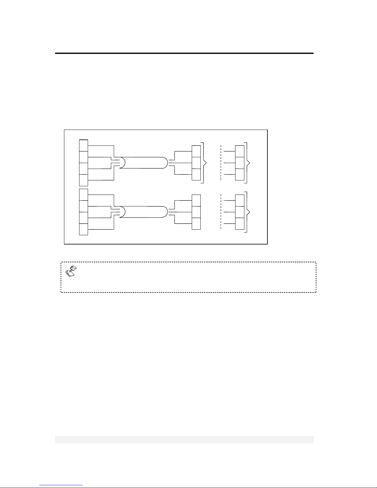
FIGURE 5 – PRINTER AND PC CABLES CONNECTION DIAGRAM ......................................... 22
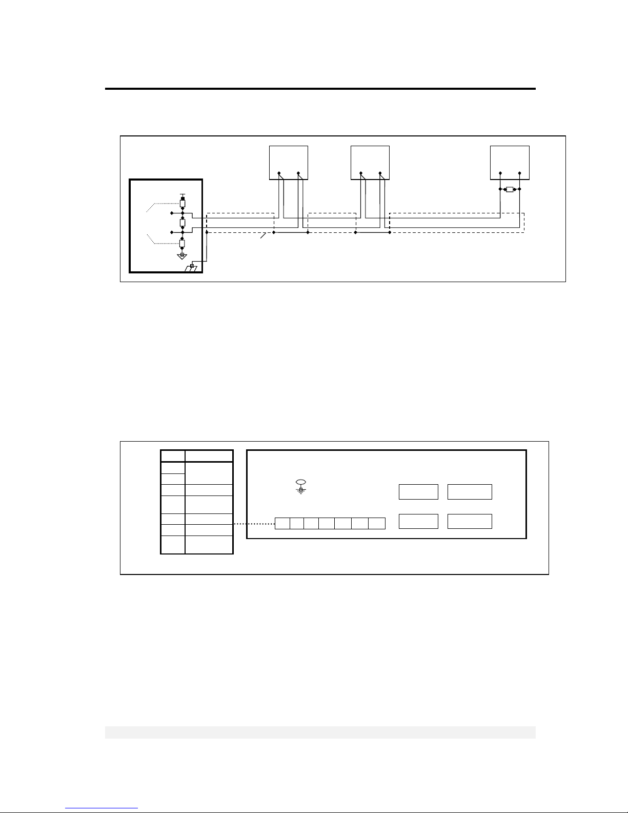
FIGURE 6 – RS485 CABLE CONNECTION DIAGRAM...................................................... 23
FIGURE 7 – POWER CABLE CONNECTION DIAGRAM ...................................................... 23
FIGURE 8 – NON-REMOVABLE STICKER ................................................................... 36
FIGURE 9 – LEAD WIRE SEAL / HARD PLASTIC STICKER ................................................. 36
FIGURE 10 - WALL MOUNT MODEL, SEALING INSTRUCTIONS ........................................... 37
FIGURE 11 – DIGITAL OUTPUT AND TILT SWITCH CONNECTION DIAGRAM............................. 63
Page 8

Legal Notice
VT300 Technical Manual, Rev. A4 viii Doc # TM-VT300-EN
Legal Notice
This manual contains information that is proprietary to Vishay Transducers Ltd.
(“VT”). No part of this publication may be reproduced in any form whatsoever
without prior written approval by VT.
Right, title and interest, all information, copyrights, patents, know-how, trade
secrets and other intellectual property or other proprietary rights relating to this
manual and to the VT300 (“the Product”), and any software components contained
therein, are proprietary products of VT protected under international copyright law
and shall be and remain solely with VT.
VT300 is a registered trademark of VT. No right, license, or interest to such
trademark is granted hereunder, and you agree that no such right, license, or
interest shall be asserted by you with respect to such trademark.
You shall not copy, reverse compile or reverse assemble all or any portion of the
Manual or the Product. You are prohibited from, and shall not, directly or indirectly,
develop, market, distribute, license, or sell any product that supports substantially
similar functionality as the Product, based on or derived in any way from the
Product. Your undertaking in this paragraph shall survive the termination of this
Agreement.
This Agreement is effective upon your opening of the packaging of the Product,
and shall continue until terminated. VT may terminate this Agreement upon the
breach by you of any term hereof. Upon such termination by VT, you agree to
return to VT the Product and all copies and portions thereof. For further
information contact VT at the address below or contact your local distributor.
Page 9

Warranty
VT300 Technical Manual, Rev. A4 ix Doc # TM-VT300-EN
Warranty
Vishay Transducers warrants all instruments it manufactures to be free from defect in materials and factory workmanship, and agrees to
repair or replace any instrument that fails to perform as sp ecified within one year after date of shipment. Coverage of computers,
cameras, rechargeable batteries, and similar items, sold in conjunction with equipment manufactured by Vishay Transducers and bearing
the identifying name of another company, is limited under this warranty to one year after the date of shipment. The warranty on non-
rechargeable batteries and similar consumable items is li mited to the delivery of goods free from defects in materials and factory
workmanship.
This warranty shall not apply to any instrument that has been repaired, worked on or altered by persons unauthorized by Vishay
Transducers in such a manner as to injure, in our sole judgment, the performance, stability, or reliability of the instrument; subjected to
misuse, negligence or accident; or connected, installed, adjusted, or used otherwise than in accordance with the instructions furnished by
us.
At no charge, we will repair, at our plant, or at an authorized repair station, or at our option, replace any of our products found to be
defective under this Warranty.
This Warranty is in lieu of any other warranties, expressed or implied, including any implied warranties of merchantability or fitness for a particular
purpose. There are no warranties which extend beyond the description on the face hereof, Purchaser acknowledges that no salesman, agent,
employee or other person has made any such presentations or warranties or otherwise assumed for Vishay Transducers any liability in connection
with the sale of any goods to the purchase. Buyer hereby waives all rights Buyer may have arising out of any breach of contract or breach of
warranty on the part of Vishay Transducers, to any incidental or consequential damages, including but not limited to damages to property,
damages for injury to the person, damages for loss of use, loss of time, loss of profits or income, or loss resulting from personal injury.
Some states do not allow the exclusion or limitation of incidental or consequential damages for consumer products, so the above
limitations or exclusions may not apply to you.
The Purchaser agrees that the Purchaser is responsible for notifying any subsequent Buyer of goods manufactured by Vishay Transducers
of the warranty provisions, limitations, exclusions and disclaimers stated herein, prior to the time any such goods are purchased by such
Buyer, and the Purchaser hereby agrees to indemnify and hold Vishay Transducers harmless from any claim asserted against or liability
imposed on Vishay Transducers occasioned by the failure of the Purchaser to so noti fy such Buyer. This provision is not intended to afford
subsequent Purchasers any warranties or rights not expressl y granted to such subsequent Purchasers under the law.
Vishay Transducers reserves the right to make any changes in the design or construction of its instruments at any time, without incurring
any obligation to make any change whatever in units previously delivered. Vishay Transducers’ sole liabilities, and Buyer’s sole remedies,
under this agreement shall be limited to the purchase price, or at our sole discretion, to the repair or replacement of any instrument that
proves, upon examination, to be defective, when returned to our factory, transportation prepaid by the Buyer, within the applicable period
of time from the date of original shipment. Return transportation charges of repaired or replacement instruments under warranty will be
prepaid by Vishay Transducers.
Vishay Transducers is solely a manufacturer and assumes no responsibility of any form for the accuracy or adequacy of any test results,
data, or conclusions which may result from the use of its equipment.
The manner in which the equipment is employed and the use to which the data and test results may be put are completely in the hands of
the Purchaser. Vishay Transducers shall in no way be liable for damages consequential or incidental to defects in any of its products.
This warranty constitutes the full understanding between the manufacturer and buyer, and no terms, conditions, understanding or
agreement purporting to modify or vary the terms hereof shall be binding unless hereafter made in writing and signed by an authorized
official of Vishay Transducers.
Page 10
Safety Instructions
VT300 Technical Manual, Rev. A4 x Doc # TM-VT300-EN
Safety Instructions
The following instructions serve as a general guide for the safe operation and
maintenance of the VT300.
Safety Symbols
This symbol indicates potential safety hazards regarding product operation
or maintenance to operator or service personnel.
General Safety Practices
Do not touch or tamper with the power supply when the power cord is connected.
Line voltages may be present even when the product is powered off or a fuse is
blown.
Before working on equipment connected to power lines or to other devices, remove
jewelry or any other metallic object that may come into contact with energized
parts.
The product is intended to be grounded during normal use. Grounding is provided
by connecting the mains plug to a wall socket with a protective earth terminal. The
earth lug provided on the product should be connected to the protective earth at
all times, by a wire with a diameter of 18AWG or wider.
Always connect the ground first and disconnect it last. Do not connect data cables
to ungrounded equipment. Make sure that all other cables are disconnected before
disconnecting the ground.
Special Safety Warnings
Welding on or in the vicinity of the equipment is strictly prohibited.
Use reliable lightening conductors to prevent static loads caused by
thunderstorms.
Page 11

Safety Instructions
VT300 Technical Manual, Rev. A4 xi Doc # TM-VT300-EN
Connection of AC Mains
Make sure that the electrical installation complies with local codes. Always connect
the AC plug to a wall socket with a protective ground.
The maximum permissible current capability of the branch distribution circuit that
supplies power to the product is 16A. The circuit breaker in the building installation
should have high breaking capacity and must operate at short-circuit current
exceeding 35A.
Always connect the power cord first to the equipment and then to the wall socket.
If the power cord cannot be readily disconnected in case of emergency, make sure
that a readily accessible circuit breaker or emergency switch is installed in the
building.
Operating Environment
Ambient
Temperature
Storage temperature: -10C to +70C (14F to 158F).
Operating temperature: -10C to +40C (14F to 104F).
Humidity 40% to 90% RH (non condensing).
Vibration Severe vibration can affect the accuracy of weighing and damage components.
Air The air surrounding the product should be dust-free and should not contain
corrosive gasses or other materials that could adversely effect the product.
Electromagnetic
Fields
Heavy electrical equipment should not be installed near to the weighing
apparatus.
Incoming and
Outgoing Signals
Relays and contacts connected to the equipment must have reliable and
effective interference suppression. This also applies to other equipment within
3 meters of the equipment.
Page 12

Declaration of Conformity
VT300 Technical Manual, Rev. A4 xii Doc # TM-VT300-EN
Declaration of Conformity
Non-Automatic Weighing Instrument (III)
Manufacturer Vishay Transducers
Type/Model VT300
EC Type Approval
Certificate Number
DK 0199.62
Corresponds to the production model described in the EC Type Approval Certificate
and to the requirements of the Council Directive 90/384/EEC as amended and to
the requirements of the following EC Directives:
EN 45501:1994, The Metrological Aspects of Non-Automatic Weighing Machines.
EN 55022:1987, Limits and Methods of Measurement of Radio Interference
Characteristics of Information Technology Equipment.
EN 60950:1992, Safety of Information Technology Equipment.
Date
April 30, 2004
Signature
Benny Shaya, Director R&D/Operations Instruments
Being the responsible person employed and appointed by Vishay Transducers.
Page 13

About this Document
VT300 Technical Manual, Rev. A4 xiii Doc # TM-VT300-EN
About this Document
This document provides technical information for the VT300 Weighbridge Indicator.
It is intended for technical staff, and explains how to install, set up and configure
the indicator, as well as troubleshoot and service it.
For information on how to use the product, see the VT300 User’s Guide.
Chapters and Their Contents
1 Technical
Specifications
General indicator specifications; analog input/output
specs; and digital input/output specs.
Pg. 15
2 Installation Installing and connecting the indicator. Pg. 18
3 Display, Keys and
Menus
Using the VT300 display, keypad and menus;
detailed outline of menus, submenus and options.
Pg. 24
4 Calibration Performing standard weight calibration and
electronic calibration.
Pg. 32
5 General System
Parameters
General parameters in the SYSTEM > 1/2CAL > PAR,
SYSTEM > SET > OPER and SYSTEM > PRP menus.
Pg. 38
6 Serial Communication Setting up communication with printers, host PCs
and other external devices.
Pg. 43
7 Outputs and Digital
Input
Connecting and using the digital input (tilt switch),
digital outputs (setpoints) and analog output.
Pg. 62
8 Service Operations
and Testing
How to set a PIN number, set date and time, view
load cell mV, test the keypad and display, and
perform other service and testing operations.
Pg. 69
9 Special Weighbridge
Operations
Customizing weighbridge descriptions, and
performing batch weighings.
Pg. 75
10 Troubleshooting and
Service
Errors, causes and suggested corrective actions;
maintenance and service instructions.
Pg. 78
Page 14
About this Document
VT300 Technical Manual, Rev. A4 xiv Doc # TM-VT300-EN
Style Conventions
Verdana
Regular text.
Arial Bold
Commands, keys and other parts of the user interface.
Arial Italics
Names of classes, methods, arguments, exceptions, properties, etc. Also used
for special terms, the first time they appear.
Monospace
Text displayed on the LCD or on a computer attached to the product.
Notes, which offer an additional explanation or a hint on how to overcome a
common problem.
Warnings, which indicate potential safety hazards regarding product operation
or maintenance to operator or service personnel.
Page 15

Technical Specifications
General
VT300 Technical Manual, Rev. A4 15 Doc # TM-VT300-EN
1 Technical Specifications
1.1 General
CPU MCU 89C51RD, 64KB Flash ROM, 1KB RAM, 64KB serial EEPROM, real-time clock.
Communication • Serial port 1: RS232C Full duplex, 2400 baud, 1 start, 7 data bits/even parity
or 8 data bits/no parity.
• Serial port 2: (optional): RS232 or RS485 half duplex, 2400-57600 baud, no
or even parity, 7 or 8 data bits.
Display 16 character LCD display (14.5mm height).
Annunciators Net, no motion, minus sign, zero, range 1 and 2.
Keyboard 27-key membrane type with tactile feedback.
Approvals EU type approval, 10,000 divisions, 0199.62.
Accuracy class III.
Resolution Selectable up to 990.000dd (in accordance with regulations).
Max tare effect Full scale (100%).
Auto zero track Off or 0.5dd, setup-selectable.
Weight digits 4, 5 or 6.
Weight steps 1, 2, 5, 10, 20, 50, 100, 200.
Digital filter FIR automatically adjusted to conversion speed, plus post filtering (rolling
average of 1, 2, 4, 8, 16, 32 samples).
Calibration methods Dead load, span and scale parameters via keyboard commands. Calibration can
be performed either by weighing or by entering load cell mV values.
Self diagnostics Hardware and software – MCU watchdog.
Memory failure and I/O failure – program check.
Page 16
Technical Specifications
Analog Input
VT300 Technical Manual, Rev. A4 16 Doc # TM-VT300-EN
1.2 Analog Input
A second analog input may be added as an option, if no analog output is
needed. The same specifications apply.
Load cell excitation ±5V switched polarity or +5VDC with sense.
Connection 6-wire technique. Max 10 load cells, 350Ohm each.
Signal range -0.25 to 1.75mV (Gain=10), -0.25 to 3.75mV (Gain=20).
Sensitivity • Approved scales: min 0.4µV / digit (VSI).
• Non-approved scales: min 0.1µV / digit.
Input amplifier Input noise 0.3µVp-p, input bias current 10nA typical.
A/D Converter Sigma delta 550.000 internal counts max. Conversion speed: 3, 7, 14, 28, 57,
70Hz (selectable).
Linearity Within 0.002% of full scale.
Span temp coefficient
≤ 2ppm/°C.
Zero temp coefficient
≤ 2ppm/°C.
Long-term stability 0.005% of full scale per year.
1.3 Analog Output (Optional)
If no analog output is needed, a second analog input may be added (see 1.2
above). Analog Output is Powered by an external 24VDC (See section 7.1.2 for
specification).
Current or voltage
Selected via jumper JP1 on printed circuit board 761 (see section 7.4.1).
Current output 0-20mA or 4-20mA. Max load resistance 1KΩ (line + termination).
Voltage output 0.02-10V. Min load resistance 1KΩ.
Resolution • Internal: 16 bits.
• External: 16 bits, or in accordance with regulation.
Linearity Better than 0.01% of FSR.
Thermal stability 50ppm/°C typical.
Short-circuit
protection
25mA indefinite duration.
Page 17

Technical Specifications
Digital Input
VT300 Technical Manual, Rev. A4 17 Doc # TM-VT300-EN
1.4 Digital Input
Input voltage 9-24VDC, positive common, optoisolated to 2.5kV.
Input resistance 3.3KΩ.
On delay 2msec max.
Off delay 2msec max.
1.5 Digital Outputs
Output voltage 24VDC ±10% transistor (source) darlington, positive common.
Max current 100mA, leakage current 100µA.
Max off-state voltage 30VDC.
On delay 2msec max.
Off delay 2msec.
Page 18
Installation
Site Requirements
VT300 Technical Manual, Rev. A4 18 Doc # TM-VT300-EN
2 Installation
2.1 Site Requirements
The mounting location must be a stable surface, free of vibrations, heat or humidity.
Avoid direct sunlight on the front of the instrument. The unit should be placed at the
correct height to allow easy reading of the display and convenient keyboard
operation.
2.2 Mounting the Indicator
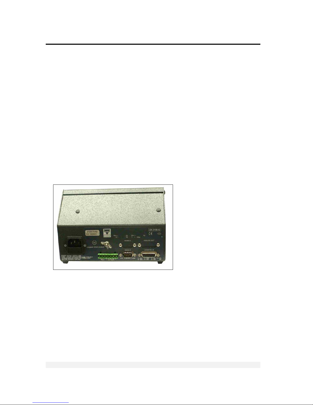
2.2.1 Desktop Model (Aluminum Enclosure)
All connections to the instrument are made through the rear panel connectors. Strainrelief clamps should be used. The shield should be connected to the metal frame of
the connector. The rear of the VT300 desktop model is shown in Figure 1.
Figure 1 – Desktop model, front and rear view
Page 19
Installation
Mounting the Indicator
VT300 Technical Manual, Rev. A4 19 Doc # TM-VT300-EN
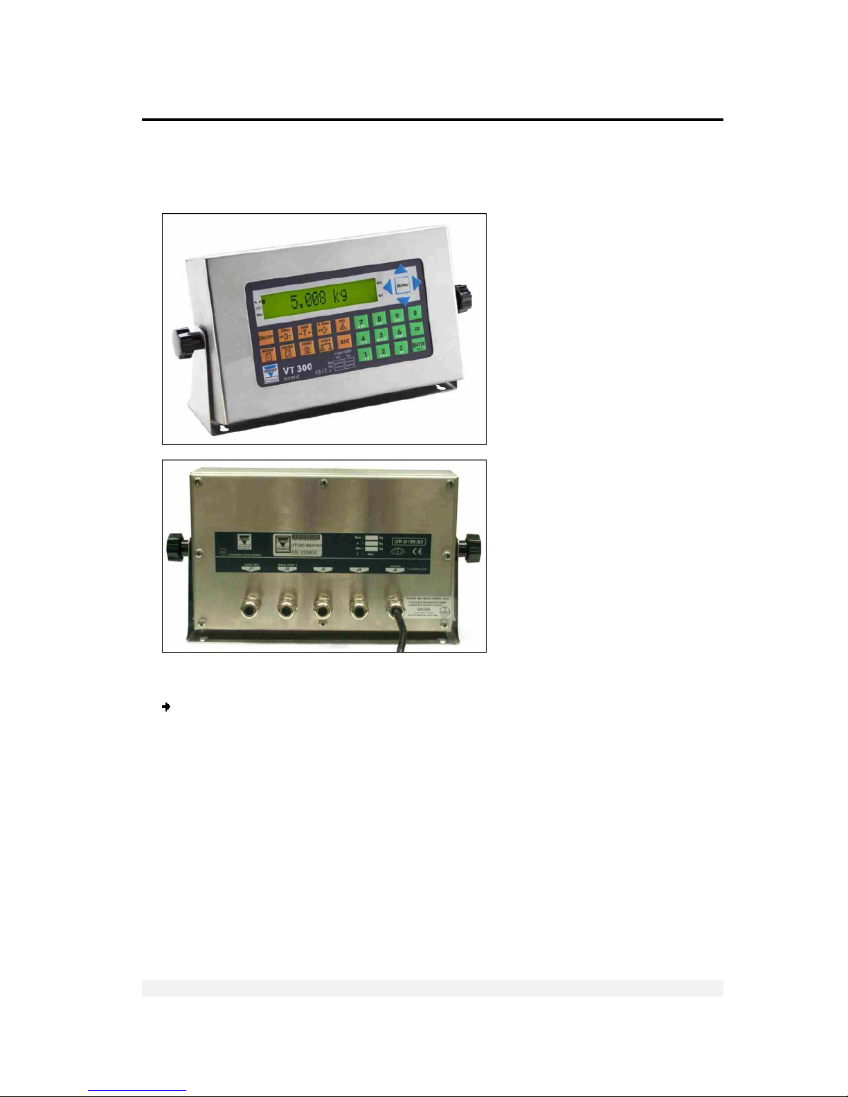
2.2.2 Wall-Mount Model (Stainless Steel Enclosure)
Front and rear views of the unit are shown in Figure 2.
Figure 2 - Wall-mount model, front and rear views
To connect the indicator to the stainless steel wall-mount:
1. Remove the rear panel and lift it carefully.
2. Insert the cables via the cable glands. Strip and connect the cables, as detailed in
sections 2.3, 2.4 and 2.5.
3. Connect the cable shield, either between the plastic and the metal case of the cable
glands, or to the screws supporting the PCBs.
4. Re-install the rear panel.
Page 20
Installation
Connecting Load Cells
VT300 Technical Manual, Rev. A4 20 Doc # TM-VT300-EN
2.3 Connecting Load Cells
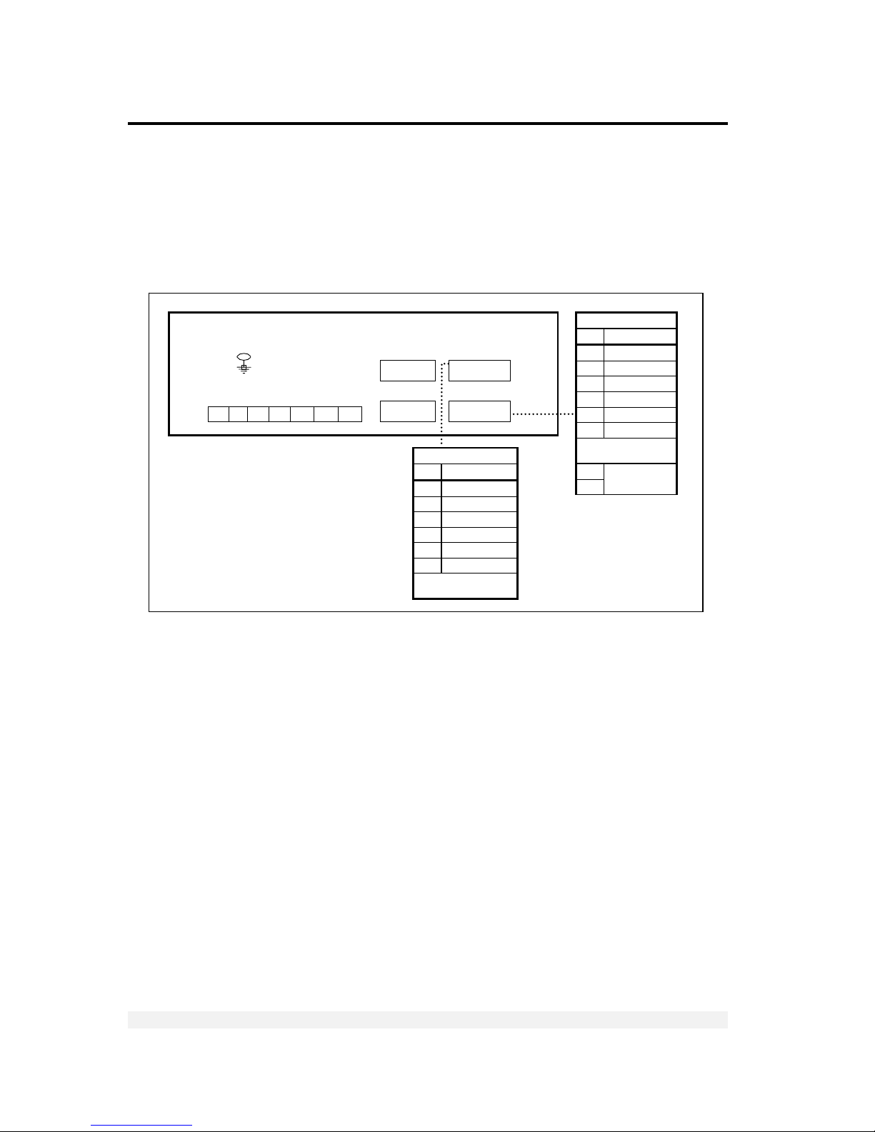
2.3.1 Desktop Model (Aluminum Enclosure)
Use 6 x 0.5mm2 shielded cable for load cell connections. Connect the load cells
according to the diagram below.
Figure 3 – Load cell connection diagram for des kto p model
1 2 3 4 5 6 7
+ - I1 CI O1 O2 +Co
LOAD CELL 1
Pin Description
1 Excitation (-)
2 Sense (-)
3 Sense (+)
4 Excitation (+)
5 Signal (-)
6 Signal (+)
D-Type Metal Case
(Shield)
7
8
Calibration
Enable
COM 2
COM 1
Load Cell 2
or
Analo
g
Output
Load Cell 1
DB9 fem
DB9 male
DB15
fem/male
DB15 fem
L
OAD CELL 2 (DB15 F)
Pin Description
1 Excitation (-)
2 Sense (-)
3 Sense (+)
4 Excitation (+)
5 Signal (-)
6 Signal (+)
D-Type Metal Case
(Shield)
Page 21
Installation
Connecting Load Cells
VT300 Technical Manual, Rev. A4 21 Doc # TM-VT300-EN
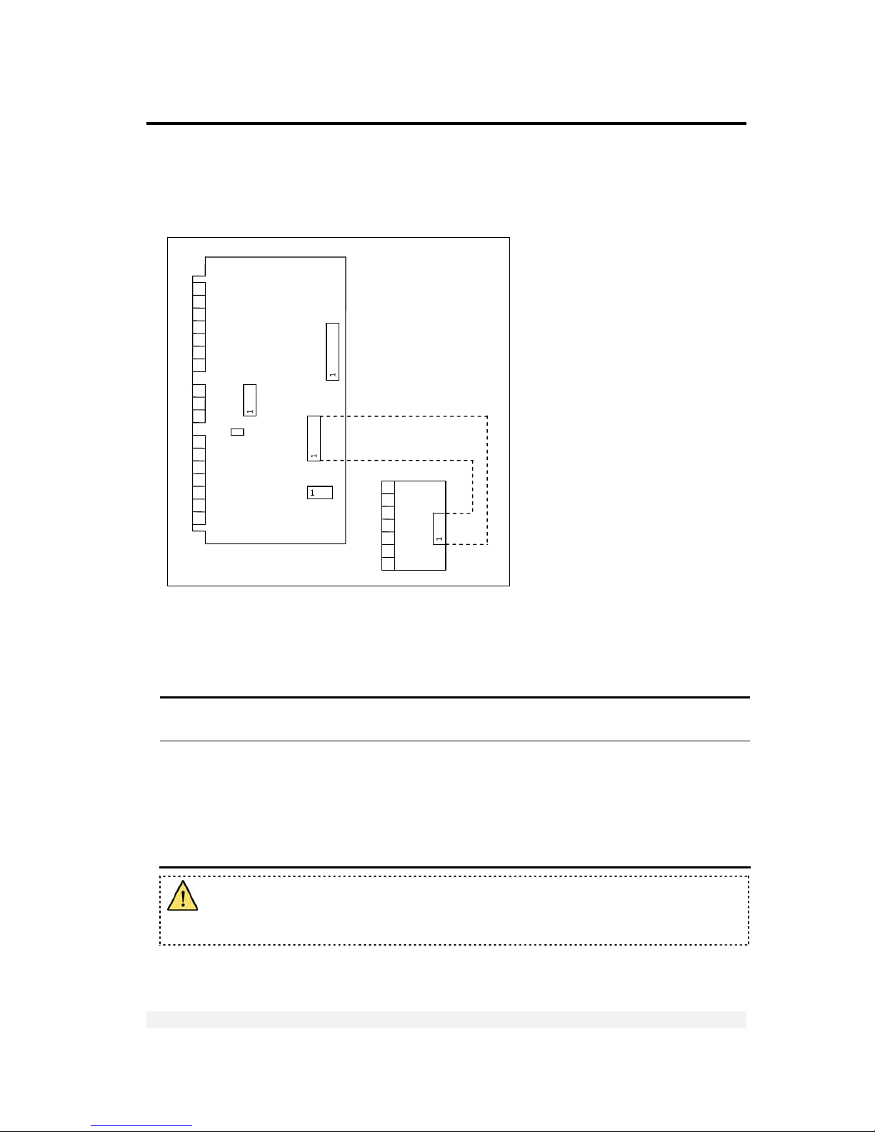
2.3.2 Wall-Mount Model (Stainless Steel)
Use 6 x 0.5mm2 shielded cable for load cell connections. Connect the load cells
according to the diagram below.
Figure 4 – Load cell connec tion diagram for wall-mou nt model
2.3.3 Load Cell Operating Parameters
The load cell utilization ranges are listed in the table below.
Excitation 5VDC, fixed or alternating polarity (setup-selectable) for 10 load cells of 350Ω
each.
Gain / input ranges • For load cell output of 10mV, gain permitted is between -0.25 and 1.75mV/V.
• For load cell output of 20mV, gain permitted is between -0.25 and 3.75mV/V.
The load cells must be chosen so that the input signal to the controller is at
least 0.4µV per scale increment. For load cell output less than 0.4µV/digit, the
controller will still be stable but the full temperature range accuracy is not
guaranteed.
Do not run signal cables together with power cables. Connect the shielding only
where indicated in the drawing. Never use a Megger to check wiring. Never use
plastic insulating tape on load cell connections.
+
POWER
¯
JP1
+
INPUT
¯
OUT1
OUT2
COM
TX RX
SGND
SHIELD
+ SIG
– SIG
+ EX
+ SEN
- SEN
- EX
PCB 801
PCB
765
SHLD
+SIG
–SIG
+EX
+SEN
–SEN
–EX
7 6 5
4
3 2 1
7 6 5
4
3 2 1
7 6 5
4
3 2 1 3 2
1
Page 22
Installation
Serial Connections
VT300 Technical Manual, Rev. A4 22 Doc # TM-VT300-EN
2.4 Serial Connections
For RS232C connection, use 3 x 0.34mm
2
shielded cable.
For RS485 connection, use 2 x 0.34mm
2
shielded twisted pair cable.
2.4.1 Printer and PC Cables
Figure 5 – Printer and PC cables connection diagram
Only the aluminum enclosure has a DB9 connector. The steel enclosure has a
screw terminal on the internal card, to which you should attach the individual
wires.
2.4.2 RS485 Cable Connections
The terminal block on the RS485 board enables connecting two pairs of wires (A, B):
One wire pair for connecting the incoming cable.
A second wire pair for a daisy-chain connection to the next unit on the RS485
bus.
Max 15m
Max 15m
T
o
PC
DB25 Female
Printer DB25 Male
DB9
Metal
Case
3
5
2
3
5
2
DB9
Fem
DB9
Metal
Case
DB9
Fem
Shield
TX GRN
GND BRN
DTR WHI
Shield
TX GRN
GND BRN
DTR WHI
GRN RX
BRN GND
WHI
DTR
GRN RX
BRN GND
WHI
DTR
RX
GND
T
X
RX
GND
DTR
3
7
20
2
5
3
3
7
2
3
7
2
Printer DB25 Male
OR
T
o
Serial
Printer
DB9 Female OR
Page 23
Installation
Connecting Power
VT300 Technical Manual, Rev. A4 23 Doc # TM-VT300-EN
The RS485 cabling configuration is illustrated in Figure 6 below.
Figure 6 – RS485 cable connection diagram
2.5 Connecting Power
VT300 indicators are powered by 85-265VAC, via an internal power supply board. The
mains power cable is supplied with the instrument.
Power should be isolated from other data processing equipment.
Verify that the AC power socket outlet is properly protected. For optimum EMC
performance, keep the length of cable shielding inside the enclosure as short as
possible.
Figure 7 – Power cable connection diagram
1 2 3 4 5 6 7
+ - I1 CI O1 O2 +Co
Pin Description
1
2
Power
9-15 VDC
3 Input 1
4
Input
Common (-)
5 Output 1
6 Output 2
7
Output
Common (+)
COM 2
COM 1
Load Cell 2
or
Analog Outp ut
Load Cell 1
DB9 fem
DB9 male
DB15
fem/male
DB15 fem
Network
Biasing
Resistors
Chassis
Earth
470R
150
R
470R
A
B
RT
+V
White
Shield
Slave #1
(
VT x00)
Slave #2
(
VT x00)
(Up to 30
slaves)
…
Slave #30
(VT x00)
A
B
A
B A B
RT
120R
Termination
Resistor
2X0.34mm2 twisted pair shielded
Max cable length: 1000m
Maste
r
Page 24
Display, Keys and Menus
The Display
VT300 Technical Manual, Rev. A4 24 Doc # TM-VT300-EN
3 Display, Keys and Menus
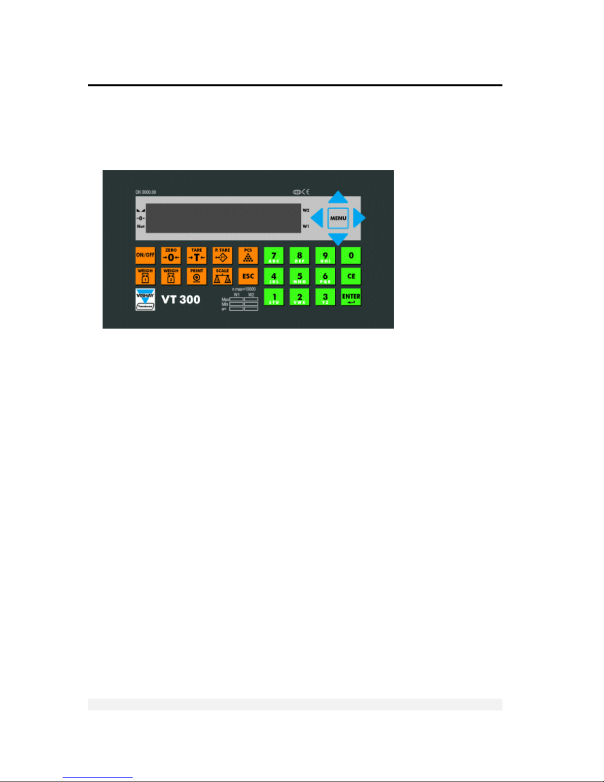
The VT300 front panel can be divided into four areas:
A sixteen-character dot matrix display shows weight information, status
information, and the names of menus and functions.
The function keypad, with ten orange keys, allows you to turn the unit on and off
and perform the most common operations.
A navigation area (to the right of the display) allows you to access and navigate
the menu, which contains more advanced operations.
An alphanumeric keypad, with 12 green keys, allows you to enter numbers and
letters.
3.1 The Display
The VT300 has an LCD display. There are three status annunciators on the left of the
display and two more on the right of the display. Small dots (status annunciators) may
appear next to one or more of these, to show status information such as whether the
scale has been tared or not.
Page 25

Display, Keys and Menus
The Display
VT300 Technical Manual, Rev. A4 25 Doc # TM-VT300-EN
3.1.1 Status Annunciators
There are several icons at the left of the display. A dot shows up next to these to
indicate the current status of the scale or indicator. Status annunciators are often
important to understand what is being shown on the display.
Stable
Active – the scale is stable (necessary for ZERO, T and PRINT).
Inactive – the scale is not stable.
Center of Zero Active – the current weight is at center of zero (or at manual zero).
Inactive – the scale is above or below center of zero.
Net Weight Active – the display is showing net weight.
Inactive – the display is showing gross weight.
S1
Scale 1 Appears on the right of the display to show that the indicator is set to scale 1.
S2
Scale 2 Appears on the right of the display to show that the indicator is set to scale 2.
S0
Sum of Scales Appears on the right of the display to indicate that the display shows the sum of
the weight on scales 1 and 2.
W1 The scale is currently in weight range 1.
W2 The scale is currently in weight range 2.
3.1.2 Common Messages Shown on the Display
Message type Meaning
352.0
Weight of the item on the scale.
24509
Approximate number of units on the scale.
319.0
(
active)
Net weight, or number of units calculated after subtracting the container’s weight.
OVER RANGE
Over range. The item on the scale weighs more than the maximum capacity of the
scale, or the load cell signal is too high.
UNDER RANGE
Under range. The item on the scale weighs less than the minimum capacity of the
scale, or the load cell signal is too low.
E15: PWRUP
ZERO
An error has occurred (see section 10.1.1). In some cases, you can ignore the error
and continue working by pressing ESC.
xxxxxx
Software model number, shown during the power-up sequence.
xxxxxx
Software version issue date, shown during the power-up sequence.
ZERO SCALE
Automatic zeroing, performed at the end of the power-up sequence.
Other types of messages may be shown when you perform specific operations, such
as editing the tare value or displaying battery status.
Page 26
Display, Keys and Menus
Front Panel Keys
VT300 Technical Manual, Rev. A4 26 Doc # TM-VT300-EN
3.2 Front Panel Keys
The keys on the VT300 front panel can serve two functions:
Performing common operations and accessing the menu.
Entering alphanumeric information.
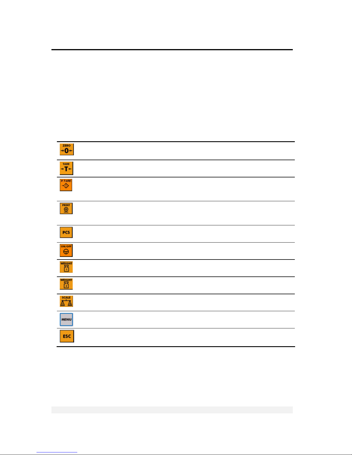
3.2.1 Using Keys to Perform Operations
Key Description Related operations Refer to
Press to zero the scale*. Only works within the zero
range.
Manual zeroing User’s Guide,
section 3.1
Press once to tare the scale*. Press again to view
gross weight.
Taring using current
weight
User’s Guide,
section 3.2
Press to enter a preset tare. Enter the tare value
using the alphanumeric keypad and press ENTER. To
cancel and view gross weight, press ESC.
Preset tare User’s Guide,
section 3.3
When you press this key, the current weight* is
printed to the printer, output to an attached
computer, and added to the accumulated total.
Printing
Section 6.2.1
Press to switch between Weighing Mode and
Counting Mode.
Counting pieces,
weighing
User’s Guide,
chapters 4, 6
Press to turn the indicator on, or to switch it off
when it is running.
Starting the indicator -
Press to perform a first weighing of a vehicle with
unknown tare.
Weighing, printing User’s Guide,
section 5.1.2
Press to weigh a vehicle with known tare, or to
perform a second weighing.
Weighing, printing User’s Guide,
chapter 5
Toggles between scale 1, scale 2 and the sum of
both scales (if two scales are connected).
Two-scale operation -
Enters the menu. The arrows around this button allow you to navigate the
menu.
Section 3.3
Cancels the current operation, exits a menu or exits
a mode.
- -
* If the scale is not stable, the current weight cannot be used for this operation.
Page 27

Display, Keys and Menus
The Menu
VT300 Technical Manual, Rev. A4 27 Doc # TM-VT300-EN
3.2.2 Using Keys to Enter Information
Key Description
0-9 Press a key to enter a digit. When you enter a second digit, the first digit moves to the left and
the new digit takes its place. If you make a mistake, press CE to clear the display.
Press a key twice or more, quickly, to toggle the letters assigned to that key. For example, to
enter the letter ‘b’, press 7 / abc three times quickly (the first time shows the number 7). To enter
‘c’, press 7 / abc four times.
Confirms the current operation or the information entered.
Clears the characters entered.
3.3 The Menu
The menu, accessed by pressing the MENU key ( ), allows you to perform advanced
operations like high-resolution weighing, printing and viewing alibi memory.
This subchapter explains how to use the menu and provides a summary of its
functions. All operations are explained in more detail further in this document.
3.3.1 Using the Menu
To access a function on th e m en u:
1. Press the MENU button, located to the right of the display.
2. Use the S and T arrows to scroll through the menu options.
3. Press ENTER to drill down into a submenu. You can then use the S and T arrows
to scroll through the menu or submenu options.
4. Press ESC to return to a higher menu or submenu level.
5. When you reach the desired menu option, press ENTER to confirm.
Page 28

Display, Keys and Menus
The Menu
VT300 Technical Manual, Rev. A4 28 Doc # TM-VT300-EN
3.3.2 Menu Structure and Options Summary
Main Menu
Menu option Description Refer to
WEIGH
Weighing options. Section 3.3.2,
MAIN > WEIGH
VFILE
V-File and weighbridge options. Section 3.3.2,
MAIN > VFILE
TFILE
Accumulated total options. Section 3.3.2,
MAIN > TFILE
MISC
Viewing calibration lock, viewing battery status, switching
weight display to high resolution.
Section 3.3.2,
MAIN > MISC
SYSTEM
Editing date, setting PINs, general parameters, calibration,
analog output settings, communication settings, ticket
customization, weighbridge customization, tilt switch settings,
setpoint settings, test operations.
Section 3.3.2,
MAIN > SYSTEM
Main > WEIGH
Menu option Submenu option Description Refer to
BATCH WEIGH -
Prints a series of truck weighings as a
unified ticket.
Section 9.2
PCS CNT -
Switches to Counting Mode. User’s Guide,
chapter 6
SETP -
Shows setpoint values and allows editing.
Section 7.3.1
COPY -
Copies last weighing ticket. User’s Guide,
section 7.1.1
ALIBI VIEW
Shows or prints specific alibi memory
records.
User’s Guide,
section 8.1
PRINT
Prints entire alibi memory. User’s Guide,
section 8.2
CSUM
Alibi memory functions. User’s Guide,
section 8.3
Page 29

Display, Keys and Menus
The Menu
VT300 Technical Manual, Rev. A4 29 Doc # TM-VT300-EN
Main > VFILE
Menu options Submenu options Description Refer to
PRINT TARE
Prints all truck tare values. User’s Guide,
section 9.2.1
FIRST
Prints all first weighings. User’s Guide,
section 9.2.2
ALL
Prints the entire V-File. User’s Guide,
section 9.2.3
SELECT
Prints a record for a specific truck. User’s Guide,
section 9.2.4
EDIT TARE -
Creates a new vehicle record. User’s Guide,
section 9.1
CSUM -
Checks V-File memory. User’s Guide,
section 9.3
DEL TARE
Deletes all truck tare values. User’s Guide,
section 9.4
FIRST
Deletes all first weighings. User’s Guide,
section 9.4
ALL
Deletes the entire V-File. User’s Guide,
section 9.4
SELECT
Deletes a record for a specific truck. User’s Guide,
section 9.4
SIZE
Shows the number of records stored in
the V-File, and space available.
User’s Guide,
section 9.5
Main > TFILE
Menu option Description Refer to
STOT Subtotal of net weights. Press PRINT to print, CE to reset.
User’s Guide,
section 4.3.2
TOTAL Accumulated total of net weights. Press PRINT to print, CE to reset.
User’s Guide,
section 4.3.2
Page 30

Display, Keys and Menus
The Menu
VT300 Technical Manual, Rev. A4 30 Doc # TM-VT300-EN
Main > MISC
Menu option Description Refer to
INFO
Displays the indicator model and serial number. -
1OIML
Displays the audit trail counter for scale 1.
Section 4.5.3
2OIML
Displays the audit trail counter for scale 2.
Section 4.5.3
BATTERY
Displays remaining battery capacity as % of max capacity.
Section 8.1.4
HIGH RES
Increases the weight display resolution 10 times. User Guide,
section 4.2
Main > SYSTEM
Menu option Submenu option Description Refer to
SYSTEM DATE
Allows editing date, time and serial print
number (user password protected).
Section 8.1.2
PIN PIN SYS
Setting and changing system password.
Section 8.1.1
PIN OPER
Setting and changing operator password.
Section 8.1.1
PRP Contains one parameter: S.EMPTY.
Chapter 5
1CAL PAR
Scale 1 parameters, including number of
display digits, position of decimal points,
A/D gain, zero range.
Section 5.2
ZERO
Dead-load calibration (standard or
electronic) for scale 1.
Sections 4.2.1,
4.3.2
SPAN
Maximum weight calibration (standard or
electronic) for scale 1.
Sections 4.2.2,
4.3.3
INIT
Resets calibration parameters for scale 1.
Section 8.1.3
WRITE
Stores scale 1 calibration parameters in
persistent memory.
Section 4.4
2CAL PAR
Scale 2 parameters.
Section 5.2
ZERO
Dead-load calibration for scale 2.
Sections 4.2.1,
4.3.2
SPAN
Maximum weight calibration for scale 2.
Sections 4.2.2,
4.3.3
INIT
Resets calibration parameters for scale 2.
Section 8.1.3
WRITE
Stores scale 2 calibration parameters in
persistent memory.
Section 4.4
Page 31

Display, Keys and Menus
The Menu
VT300 Technical Manual, Rev. A4 31 Doc # TM-VT300-EN
Main > SYSTEM (cont.)
Menu option Submenu option Description Refer to
D/A CAL -
Analog output parameters, including
current/voltage, net/gross, resolution.
Section 7.4.2
SET OPER
Operational parameters, including data
format, display brightness, custom print
formats enable/disable, totalizer
enable/disable.
Section 5.3
1COM
Output format and parameters for
communication port 1.
Section 6.2.1
2COM
Output format and parameters for
communication port 2.
Section 6.2.2
INIT Resets all parameters in the SET menu.
Section 8.1.3
FORM (DOWNLOAD,
DEFAULT)
Downloads custom ticket formats and
resets ticket formats to default.
Section 6.5
REFR (EDIT)
Allows viewing and editing weighbridge
descriptions.
Section 9.1
TILT
Tilt switch settings.
Section 7.5
SETP
Allows viewing and editing setpoint
values (both setpoints).
Section 7.3.1
LOCK KEY
Allows locking and unlocking keys on the
keypad.
Section 8.1.8
TEST A/D
Shows A/D converter count.
Section 8.1.7
CVM
Shows load cell mV output.
Section 8.1.6
I/O
Tests outputs and digital input.
Section 8.2.3
KBD
Tests keypad.
Section 8.2.2
LCD
Tests display.
Section 8.2.2
MEM
Tests ROM/RAM integrity.
Section 8.2.1
PORT
Tests communication ports.
Section 8.2.4
Page 32

Calibration
Selecting Calibration Method
VT300 Technical Manual, Rev. A4 32 Doc # TM-VT300-EN
4 Calibration
Before you can calibrate the scale, you must ensure that jumper JP1 is not in the
sealed position (see section 4.5). You must also select a calibration method, using the
CAL MODE scale parameter (see section 4.1). The following methods are available:
Standard weights calibration, in which you record the center of zero, and then
place a known weight on the scale and enter its weight (see section 4.2).
Electronic calibration, in which you enter the mV value of the minimum and
maximum weight (see section 4.3).
Calibration (either standard or electronic, depending on your CAL MODE selection) is
performed using the SYSTEM > 1CAL or SYSTEM > 2CAL menu.
If you have two scales connected to the indicator, each scale has its own
calibration parameters; all the parameters in the 1CAL menu relate to scale 1,
while all the parameters in the 2CAL menu relate to scale 2.
After calibrating the scale, you must store calibration data in persistent memory (see
section 4.4), and seal the calibration lock (see section 4.5).
4.1 Selecting Calibration Method
Before calibrating the scale, you should select the calibration method – standard or
electronic – using the instructions below.
To select a calibration method:
1. Press MENU and navigate to the SYSTEM > 1CAL > PAR menu. Or, if you want to
set the calibration method for scale 2, navigate to SYSTEM > 2CAL > PAR.
2. Scroll through the parameters until you reach CAL MODE. Press ENTER.
3. Use S and T to select one of the options:
WEIGHT – standard weight calibration.
ELECTR – electronic calibration.
4. Press ENTER to confirm your selection.
If you selected WEIGHT, proceed to section 4.2 to perform standard
calibration.
If you selected ELECTR, proceed to section 4.3 to perform electronic
calibration.
Page 33

Calibration
Calibration with Standard Weights
VT300 Technical Manual, Rev. A4 33 Doc # TM-VT300-EN
4.2 Calibration with Standard Weights
To perform calibration with standard weights, you must set the CAL MODE scale
parameter to WEIGHT (see section 4.1).
Calibration with standard weights is done in two stages:
Zero calibration, in which you take a weight measurement when there is nothing
on the scale (see section 4.2.1). This is also called dead-load adjustment.
Span calibration, in which you place a known weight on the scale, and manually
enter its correct weight (see section 4.2.2).
You must perform both of the above for the scale to be calibrated properly.
After calibrating the scale, you must save the values in permanent memories by
entering the setup menus and selecting the WRITE option (see section 4.4). It
is also advised to lock calibration (see section 4.5).
4.2.1 Zero (Dead-Load) Calibration
To perform zero calibration:
1. Press MENU and navigate to SYSTEM > 1CAL > ZERO. Or, if you wish to calibrate
scale 2, navigate to SYSTEM > 2CAL > ZERO.
2. Press ENTER. The display shows EMPTY SCALE. Clear the scale, and wait about 10
seconds.
3. Press ENTER to record the zero position. The display shows WAIT… as 64
measurements are taken and an average calculated. This should take about 10
seconds.
4. The display should now show 0. If the zero point is not accurate, press ESC and go
back to step 1.
4.2.2 Span Calibration
To perform span calibration:
1. Press MENU and navigate to SYSTEM > 1CAL > SPAN. Or, if you wish to calibrate
scale 2, navigate to SYSTEM > 2CAL > SPAN.
2. Press ENTER. The display shows WEIGHT, followed by the maximum capacity of the
scale. Enter the correct calibration weight using the numeric keypad.
3. Press ENTER to confirm the calibration weight. The display shows LOAD SCALE.
4. Place the calibration weight on the scale, and wait about 10 seconds.
5. Press ENTER. The display shows WAIT… as 64 measurements are taken and the
span coefficient calculated. This should take about 10 seconds.
6. Span calibration is now complete. If the weight shown is not accurate, press ESC
and go back to step 1.
Page 34

Calibration
Electronic Calibration (E-CAL)
VT300 Technical Manual, Rev. A4 34 Doc # TM-VT300-EN
4.3 Electronic Calibration (E-CAL)
To perform electronic calibration, you must set the CAL MODE scale parameter to
ELECTR (see section 4.1).
Electronic calibration involves setting two values, using the indicator keypad:
The signal level in mV, corresponding to the zero, or dead-load point (see section
4.3.2).
The signal level in mV, corresponding to the maximum capacity of the scale (see
section 4.3.3).
To learn how to calculate these values from the load cell specifications provided by
the manufacturer, see section 4.3.1 below. You must perform both of the above for
the scale to be calibrated properly.
After calibrating the scale, you must save the values in permanent memories by
accessing the calibration menu and selecting WRITE (see section 4.4). It is also
advised to lock calibration (see section 4.5).
4.3.1 Calculating Calibration Values
Consider the following example. A scale has maximum capacity 30/60kg,
e=0.010/0.020kg, with 4 load cells, each with rated capacity 50kg (2mV) and dead
load 1.940kg. The load cell data, as noted in the manufacturer data sheet, is shown
in the following table.
Load cell Output at 50kg Zero balance
L/C1 1.9793mV 0.0257 mV
L/C2 1.9392mV 0.0276 mV
L/C3 1.9577mV 0.0553 mV
L/C4 1.9640mV -0.0022 mV
To calculate the dead-load and span calibration values:
1. Calculate an average of the load cells’ rated output. In the example above, this
equals (1.9793+1.9392+1.9577+1.9640)/4=1.9600mV.
2. Calculate the combined output of the load cells when the scale is at maximum
capacity. In the example above, this equals 1.9600x60/4x50=0.5880mV. This is
the span calibration value.
3. Calculate an average of the load cells’ zero balance. In the example above, this
equals [0.0257+0.0276+0.0553+(- 0.0022)]/4=0.0266mV.
4. Calculate the scale dead-load. In the example above, this equals
1.9600mV*[1.940Kg/(4*50Kg)]=0.0190mV.
Page 35

Calibration
Storing Calibration Data
VT300 Technical Manual, Rev. A4 35 Doc # TM-VT300-EN
5. Calculate the overall dead-load by adding together the load cell zero balance and
the scale dead-load (calculated in step 4). In the example above, this equals
0.0266+0.0190=0.0456mV. This is the dead-load calibration value.
4.3.2 Setting Zero Calibration (Dead-Load) Value
To set the zero calibration value electronically:
1. Press MENU and navigate to SYSTEM > 1CAL > ZERO. Or, if you wish to calibrate
scale 2, navigate to SYSTEM > 2CAL > ZERO.
2. Press ENTER. The display shows DEAD LOAD: 00000.
3. Enter the overall mV of the dead-load, using the numeric keypad (see section 4.3.1
to learn how to calculate it).
4. Press ENTER to record the zero calibration value. The display shows the
corresponding weight.
4.3.3 Span (Max. Capacity) Calibration
To set the span calibration value electronically:
1. Press MENU and navigate to SYSTEM > 1CAL > SPAN. Or, if you wish to calibrate
scale 2, navigate to SYSTEM > 2CAL > SPAN.
2. Press ENTER. The display shows L/C OUT: 00000.
3. Enter the overall mV of the scale’s maximum capacity, using the numeric keypad
(see section 4.3.1 to learn how to calculate it).
4. Press ENTER to confirm the maximum capacity calibration value. The display shows
the corresponding weight.
4.4 Storing Calibration Data
After calibrating the scale (using either standard or electronic calibration), calibration
data is stored in volatile memory only, and so it is lost when the indicator powers
down. To store the calibration data permanently, follow the procedure below.
To store calibration data:
1. Press MENU and navigate to SYSTEM > 1CAL > WRITE. Or, if you calibrated scale
2, navigate to SYSTEM > 2CAL > WRITE.
2. Press ENTER. The display shows O.K.? AE=Y , CE=N.
3. Press ENTER to confirm. Calibration data is stored in persistent memory, and the
indicator restarts.
Page 36

Calibration
Locking and Unlocking Calibration
VT300 Technical Manual, Rev. A4 36 Doc # TM-VT300-EN
4.5 Locking and Unlocking Calibration
An internal jumper (JP1, located on the main printed circuit board next to the analog
circuit) must be removed to allow access to configuration and calibration parameters.
One way to seal the indicator is to prevent access to this jumper. This is done by
placing a brittle plastic sticker over one of the screws that keeps the cabinet closed.
The indicator also has an Audit Trail Counter, which is incremented every time weight
parameters or calibration data are changed, regardless of whether the change was
saved in EEPROM or not. This counter allows the authorities to check if any calibration
attempt has been made since the last inspection.
A label with an inscribed count (all digits are permanently printed and suffixed
by a hyphen) is placed on the rear side of the instrument. The label is
designated CAL-Nr, and may not be removed without destroying it.
Seals bear the verification mark of a notified body, or an alternative mark of
the manufacturer, according to Annex II, section 2.3 of Directive 90/384/EEC.
4.5.1 Sealing Indicator Enclosure with Stickers
After calibration, you can seal the indicator with two stickers:
A non-removable label, to prevent unauthorized opening of the indicator
enclosure (Figure 8)
A lead wire seal or hard plastic sticker, to prevent unauthorized tampering with
the load cell connector (Figure 9)
Figure 8 – Non-removable sticker
Figure 9 – Lead wire seal / hard plastic sticker
Page 37

Calibration
Locking and Unlocking Calibration
VT300 Technical Manual, Rev. A4 37 Doc # TM-VT300-EN
To seal the indicator:
For the wall-mount (stainless steel) model, refer to Figure 10 below.
Figure 10 - Wall mount model, sealing instructions
For the desktop (aluminum) model, either apply a non-removable sticker to
the load cell connector and to the left edge of the front panel; or fix a lead
seal to the load cell connector on one end, and to the left edge of the front
panel on the other end.
4.5.2 Securing Load Receptor
You can inscribe the serial number of the load receptor as part of the indicator
identification label.
The load receptor bears the serial number of the indicator on its data plate.
4.5.3 Checking Seal Status and Audit Trail Counter
In order to check whether the jumper is still in the sealed position, and that the audit
trail counter has not changed.
To check seal status and audit trail counter:
1. Press MENU and navigate to MISC > 1OIML. Or, if you want to check scale 2,
navigate to MISC > 2OIML.
2. Press ENTER. If JP1 is currently in the sealed position, the word SEALED appears on
the display briefly. Following this, the audit trail counter is displayed.
Lead
seal
Non-
removable
sticker
Page 38

General System Parameters
Editing Parameters
VT300 Technical Manual, Rev. A4 38 Doc # TM-VT300-EN
5 General System Parameters
Several submenus in the SYSTEM menu provide access to general system
parameters, which affect how the scale operates:
The SYSTEM > 1/2CAL > PAR menu contains parameters including the number of
display digits, the position of the decimal point, the A/D gain and the zero range
(see section 5.2).
The SYSTEM > SET > OPER menu contains parameters that effect user
operations. For example, if allows you to enable and disable the totalizer and alibi
memory storage; specify LCD brightness; specify auto power-off time delay, etc.
(see section 5.3).
The SYSTEM > PRP menu contains one parameter, S.EMPTY. This parameter
defines the maximum weight, in kilograms, that will be considered as “empty” by
the indicator.
If you have two scales connected to the indicator, parameters you define in the
latter two menus (OPER and PRP) apply to both of them. Parameters you define
in SYSTEM > 1CAL > PAR refer to scale 1 only, and parameters defined in
SYSTEM > 2CAL > PAR refer to scale 2 only.
Other menus allow you to calibrate the scale (see chapter 4); set communication
parameters (see chapter 6); and set input/output parameters (see chapter 7).
5.1 Editing Parameters
To edit parameters in one of the menus:
1. Press MENU and navigate to the menu you need, using S and T. To enter the
menu press ENTER. To return to a higher menu press ESC.
2. The names of parameters are shown on the display. Use S and T to scroll to the
parameter you wish to edit.
3. To edit the parameter, do one of the following:
If the parameter has two or more preset values, the display will show the
current value (e.g. YES). Use W and X to scroll to the value you need, and
press ENTER to confirm it.
If the parameter is numeric, enter a new value using the numeric keypad.
Press ENTER to confirm the new value.
4. If the parameter is in the 1CAL > PAR or 2CAL > PAR menu, you must perform a
WRITE operation to save the new settings to persistent memory (see section 4.4).
Page 39

General System Parameters
SYSTEM > 1/2CAL > PAR Menu
VT300 Technical Manual, Rev. A4 39 Doc # TM-VT300-EN
5.2 SYSTEM > 1/2CAL > PAR Menu
# Parameter Description Values
00 2SCL ENABLE
(only appears
in 1CAL menu)
Scale 2 enable. Activates the second scale input. This
option only appears in the 1CAL menu. If set to NO,
parameters in the 2CAL menu are ignored.
YES, NO
01 S1+S2 ENABLE
(only appears
in 2CAL menu)
*
Sum of two scales.
YES specifies that the
key should toggle between scale
1 weight, scale 2 weight and the sum of both scales.
NO specifies that the
key should only toggle between
scale 1 weight and scale 2 weight.
YES, NO
02 DISP.DIGITS Number of display digits. 4, 5, 6
03 DEC.POINT * Number of digits after decimal point. Defines the
position of the decimal point.
0-5
04 SCALE DIV. * Display resolution. 1, 2, 5, 10, 20, 50,
100, 200
05 WEIG.RANGE Two most significant digits of full load. 00-99
06 DIG. FILTER Digital filter. If x is entered, filter averages 2x samples. 0
is considered low, 3 is normal and 5 is high.
0-5
07 CONV. RATE * Number of conversions per second. If there are two
scales connected, the sum of their conversion rates
(6P+6P) must be less than 70. Otherwise the unit sets
CONV.RATE=14 for each scale.
3, 7, 14, 28, 57, 70
08 MOTION
SAMPLES
No-motion samples. Number of samples for no-motion
detection. 1 is considered low; 7 is considered high.
1-7
09 AUTO Z TRACK Auto-zero tracking, with a maximum of 0.5 display
divisions per second.
YES, NO
10 INIT ZERO Auto-zero at power up. If enabled, sets the instrument
to zero on power-up. It the starting weight is outside the
zero range, E.15 is displayed (see chapter 10).
YES, NO
11 DUAL FILTER Dual digital filter (anti-flicker). The digital filter increases
automatically when the scale is not in motion.
YES, NO
12 A/D AUTO CON Automatic clearing of A/D converter errors.
NO specifies that, when the A/D converter is enabled,
errors are automatically cleared when the cause is no
longer present.
YES specifies that A/D converter errors should remain on
the display until the operator presses ESC.
YES, NO
13 BATTERY Battery conversion. Enables battery conversion, for
battery-powered models.
YES, NO
Page 40

General System Parameters
SYSTEM > 1/2CAL > PAR Menu
VT300 Technical Manual, Rev. A4 40 Doc # TM-VT300-EN
# Parameter Description Values
14 LEAD Z BLANK Leading zero blank. Enables and disables leading zeroes
in the display.
YES, NO
15 A/D GAIN Load cell amplifier gain adjustment (A/D Gain)
2mV/V setting allows maximum utilization of 1.75mV/V.
4mV/V setting allows maximum utilization of 3.75mV/V.
10=2mV/V
(1.75mV/V utilization)
20=4mV/V
(3.75mV/V utilization)
16 AC EXC. AC/DC excitation.
YES specifies polarity should be switched at a rate
determined by the conversion rate. Switching excitation
results in a more stable zero.
NO sets load cell excitation to DC.
YES=AC
NO=DC
17 ZERO RANGE Zero range. The zero range can be set to 2% or 10% of
maximum capacity.
2%, 10%
18 DUAL MODE * Dual interval or range.
INTERV specifies that the lower display division should be
selected at the defined internal value.
RANGE specifies that the lower display division should be
selected at zero weight.
INTERV, RANGE
19 DUAL RANGE First two digits defining the limit between the two
ranges where the lower display division will be selected
automatically (Max1).
00 - 99
20 PR. BELOW
MIN
Do not print weights below minimum.
YES specifies that weights below 20 scale divisions should
not be printed.
NO specifies that weights below 20 scale divisions should
be printed.
YES, NO
21 CAL MODE Calibration method. Sets calibration to standard weights
(WEIGHT) or electronic (ELECTR). This affects the
calibration dialogs 1/2CAL > ZERO and 1/2CAL > SPAN.
WEIGHT, ELECTR.
22 UNIT SELECT Unit selection. Specifies unit used for measurement:
kilograms or pounds.
KG, LB
* Refer to Section 5.2.1 for how to set parameters when using two scales.
Page 41

General System Parameters
SYSTEM > SET > OPER
VT300 Technical Manual, Rev. A4 41 Doc # TM-VT300-EN
5.2.1 Dual-scale Connecting And Parameter Settings
To connect and set up VT300 for dual-scale operations:
1. Set parameter 2SCL ENABLE(00) to YES, DUAL RANGE(19) to 00, and CONV.RATE
(07) to a value less than 70.
2. Ascertain that the first scale is calibrated and working properly.
3. Connect the second scale to ST5, 7 pins socket in the one side and in the other
side using the mounting posts/spacers provided to:
Stainless Steel Enclosure – The main board.
Aluminum Enclosure – To the indicator’s rear panel.
4. Ascertain that the Scale 2 values for parameters DEC.POINT (02) and SCALE.DIV (03)
are the same as those for Scale 1.
5. After checking that the S2 annunciator is on,(switching with the SCALE key)
calibrate the second scale.
6. The device is now ready to work in dual-scale mode.
7. Use the SCALE key for switching between Scale1(S1 on the display) , Scale2(S2
on the display) or sum of Scale1 and Scale2(S0 on the display).
5.3 SYSTEM > SET > OPER
# Parameter Description Values
01 TOTALIZING M Enable totalizer. YES enables the accumulated total
function for users. NO disables it.
YES, NO
02 WEIGHING MEM Store first weighing in memory. If set to NO, first
weighing information is discarded and cannot be accessed
through the FIRST submenu in the VFILE menu.
YES, NO
03 REFR CODE Number of descriptions for weighbridge operations.
Specifies the number of descriptions (reference codes) the
user is prompted for during first and second weighings. By
default these are VEHICLE, CLIENT and PRODUCT.
If set to 0, weighbridge descriptions are disabled
altogether. In any event, only the first two descriptions are
stored in memory.
0-4
0=disable
descriptions
04 CODE MEM Remember last weighbridge description. Specifies
whether or not the first and second weighing dialogs
should display, for each description such as VEHICLE and
CLIENT, the value entered by the user in the previous
weighing operation.
YES, NO
Page 42

General System Parameters
SYSTEM > SET > OPER
VT300 Technical Manual, Rev. A4 42 Doc # TM-VT300-EN
# Parameter Description Values
05 WAIT UNLOAD Wait for weight to unload before printing again.
YES specifies that after printing, the indicator should not
allow the user to print again, until the scale has been
unloaded.
NO specifies that the user should be able to print again,
even if the scale has not been unloaded.
YES, NO
06 1stW PRINT Print first weighing ticket automatically.
YES specifies that the first weighing data should be
automatically printed.
NO specifies that the user should be prompted to print the
first weighing ticket, and will have the option of canceling
the printing.
Regardless of what is selected here, first weighing data is
saved to memory, unless WEIGHING MEM=NO.
YES, NO
07 USER FORMS Custom weighbridge descriptions and printing
formats.
YES specifies that service personnel should be able to
define custom weighbridge descriptions (reference codes)
and custom print formats.
NO specifies that only the default weighbridge descriptions
and print formats should be available.
YES, NO
08 KEY IN TIME Time for character selection entry (in 0.1 seconds).
00 disables alpha characters.
0-99
09 BRIGHTNESS LCD backlight brightness. Low is the least bright, MID1
is brighter, MID2 is brighter still, HIGH is brightest.
LOW, MID1,
MID2, HIGH
10 DATE FORMA Date format. Select either day-month-year (D-M-Y) or
month-day-year (M-D-Y). In either case, the numbers in
the date will be separated by hyphens (“-”).
D-M-Y, M-D-Y
11 AUTO PWR OFF Power off interval. Specifies the idle time, in minutes,
that should pass before the indicator automatically
switches itself off.
00-99
00=disable
power off
Page 43

Serial Communication
Serial Ports Configuration
VT300 Technical Manual, Rev. A4 43 Doc # TM-VT300-EN
6 Serial Communication
6.1 Serial Ports Configuration
VT300 has two serial ports, designated port 1 and port 2. Port 1 is an RS232 port.
Port 2 is an optional port installed on order, and can be either RS232 or RS485.
6.1.1 RS232 Serial Port
The port is used to connect to serial printers or personal computers.
General Asynchronous serial ASCII, RS232C standard, full duplex.
Protocol 2400 baud, 1 start, 7 data/even parity or 8 data/no parity, 1 stop bit.
OR transmit only, 9600 baud, 1 start, 7 data/even parity or 8 data/no parity, 1 stop bit.
Handshake DTR BUSY per character for fanfold printers or REQUEST PAPER END STATUS for EPSON
TM-295 slip printer.
Connection Cable gland: stainless steel enclosure or DB9 male on rear panel, aluminum enclosure
(J1 or J3). Three-conductor shielded cable, max distance 15m.
Tx = Pin 3
Rx/DTR = Pin 2
GND = Pin 5
6.1.2 RS485 Serial Port
Used to connect to a host computer, remote printer, remote display, etc.
General Asynchronous serial ASCII, RS485 half duplex.
Protocol 2400 to 57600 baud, 1 start, 7 or 8 data, 1 even parity, 1 stop bit.
Connection Cable gland: stainless steel enclosure or DB9 female on rear panel, aluminum enclosure
(J3). Two-conductor twisted-pair shielded cable, max distance 1000m. A termination
resistor 120R may be connected by shorting pins 8 and 9.
A = Pin 6
B = Pin 7
Page 44

Serial Communication
Setting Port Output
VT300 Technical Manual, Rev. A4 44 Doc # TM-VT300-EN
6.2 Setting Port Output
6.2.1 Setting Port 1 Output
You can use menu path SYSTEM > SET > 1COM > OPERATION to determine the
output for port 1. The following options are available:
TICK 3 – Printer mode. The printer driver is selected using menu path SYSTEM >
SET > 1COM > PRN TYPE.
To learn more about the standard ticket formats printed in TICK 3 mode, see
section 6.4. To learn how to customize these formats, see section 6.5.
W.OUT – continuous weight output. See section 6.3.1.
W2OUT – continuous weight output with dual scale operation. See section 6.3.2.
ALIBI – transmit alibi memory. See section 6.3.4.
9600T – set baud rate to 9600, transmit only.
NONE – deactivate the port.
The 1COM menu has additional parameters related to port 1 output, detailed below.
Parameter Description Values
PARITY/DATA Parity bits. Specifies whether there should be even parity with
7 data bits (E7) or no parity (E8).
E7, E8
PRN TYPE Printer type. Specifies which type of printer is connected to the
indicator: Epson FX (EP-FX or other similar serial printer) or TM-
295.
EP-FX, TM-295
ERROR CTRL Printer error display.
YES specifies that printer errors (DTR) should be displayed and
acknowledged by the user.
NO specifies that errors should be ignored. You must set this
parameter to NO for communication with a PC.
YES, NO
ADDRESS Port 1 network address. Used in alibi mode. This can be
different from the address set in 2COM > M/S.
Page 45

Serial Communication
Setting Port Output
VT300 Technical Manual, Rev. A4 45 Doc # TM-VT300-EN
6.2.2 Setting Port 2 Output
You can use menu path SYSTEM > SET > 2COM > OPERATION to determine the
output for port 2. The following options are available:
W.OUT – continuous weight output. See section 6.3.1.
W2OUT – continuous weight output with dual scale operation. See section 6.3.2.
A.OUT - continuous weight output with tare. See section 6.3.3.
NONE – Port is disabled.
EDP – EDP protocol output. See section 6.3.6.
R.PRN – printing data from the local printer on a remote printer. See section
6.3.7.
M/S A-Y [A=network address] – participate in a network of several indicators as
slave, with this address. See section 6.3.8.
The 2COM menu has additional parameters related to port 2 output, detailed below.
Parameter Description Values
PARITY/DATA Parity bits. Specifies whether there should be even parity with
7 data bits (E7), no parity with 7 data bits (N8) or no parity with
8 data bits (E8).
E7, N8, E8
PRN TYPE Printer type. Specifies which type of printer is connected to the
indicator: Epson FX (EP-FX or other similar serial printer) or TM-
295.
EP-FX, TM-295
ERROR CTRL Printer error display.
YES specifies that printer errors (DTR) should be displayed and
acknowledged by the user.
NO specifies that errors should be ignored. You must set this
parameter to NO for communication with a PC.
YES, NO
Page 46

Serial Communication
Output Formats
VT300 Technical Manual, Rev. A4 46 Doc # TM-VT300-EN
6.3 Output Formats
6.3.1 Continuous Weight Output
Works With Ports
Ports 1, 2 (RS232 or RS485)
Description
Net weight and status information is transmitted continuously, along with the current
tare and gross weight. No handshake is required. Used mainly for remote display or
PC. The structure of the transmitted data block is shown below.
Data Block Composition
Byte Name Description
1 Weight status Bit0 0=Normal 1=No weight display
Bit1 0=Gross 1=Net
Bit2 0=No Auto zero 1=Auto zero
Bit3 0=Within range 1=Out of range
Bit4 0=No standstill 1=Standstill
Bit5 0=Normal 1=Under minimum weighing range
Bit6 Always 1
Bit7 Zero or parity
2 Polarity “+” or “-”.
3-8 Weight 6 digits, including decimal point if any
9 Sync Carriage return (0D hex) for end of transmission.
Page 47

Serial Communication
Output Formats
VT300 Technical Manual, Rev. A4 47 Doc # TM-VT300-EN
6.3.2 Continuous Weight Output with Dual Scale Operation
Works With Ports
Ports 1, 2 (RS232 or RS485)
Description
When two scales are connected to the indicator, both their weights are transmitted
continuously in the format P+123.45 P+678.90CR. In each pair, the first block
transmitted is the weight of the first scale, and the second block transmitted is the
weight of the second scale.
For this mode of operation, the parameter settings are SYSTEM > SET > 1COM >
W2OUT, and SYSTEM > SET > 2COM > W2OUT.
Data Block Composition (for Each Scale)
Byte Name Description
1 Weight status Bit0 0=Normal 1=No weight display
Bit1 0=Gross 1=Net
Bit2 0=No Auto zero 1=Auto zero
Bit3 0=Within range 1=Out of range
Bit4 0=No standstill 1=Standstill
Bit5 0=Normal 1=Under minimum weighing range
Bit6 Always 1
Bit7 Zero or parity
2 Polarity “+” or “-”
3-8 Weight 6 digits, including decimal point if any.
9 Sync Carriage return (0D hex) for end of transmission.
6.3.3 Continuous Weight With Tare
Works With Ports
Ports 2 (RS232 or RS485)
Description
This option can be programmed using setup parameter SYSTEM > SET > 2COM >
OPERATION to A.OUT. The weight indication of each scale is transmitted continuously
along with its current tare and gross weight. The format is:
Page 48

Serial Communication
Output Formats
VT300 Technical Manual, Rev. A4 48 Doc # TM-VT300-EN
P+123.45N010.00(T/P)133.45G
Where the characters indicate:
N for Net weight.
G for Gross weight.
T for the Tare weight when the scale was manually tared, or P for the tare weight
when the tare was preset either from the device or from a PC.
Data Block Composition
Byte Name Description
1 Weight status Bit0 0=Normal 1=No weight display
Bit1 0=Gross 1=Net
Bit2 0=No Auto zero 1=Auto zero
Bit3 0=Within range 1=Out of range
Bit4 0=No standstill 1=Standstill
Bit5 0=Normal 1=Under minimum weighing range
Bit6 Always 1
Bit7 Zero or parity
2 Polarity “+” or “-”.
3-8 Weight 6 digits, including decimal point if any
9 “N” Indicates that the preceding weight is net.
10-15 Net weight 6 digits, including decimal point if any.
16 “T” or “P” “T” specifies that the preceding weight is a manual tare.
“P” specifies that the preceding weight is a preset tare.
17-22 Gross weight 6 digits, including decimal point if any.
23 “G” Indicates that the preceding weight is gross.
24 Sync Carriage return (0D hex) for end of transmission.
When Display Indication is Not Weight (Port 2 Only)
When the indicator displays something other than weight, the data string to COM2
will be as follows:
|A|XXXX|TARE VALUE|T/P|GROSS VALUE|G|CR
“XXXX” in the format above will either be blank spaces, an error message, or the
menu currently accessed by the user.
Page 49

Serial Communication
Output Formats
VT300 Technical Manual, Rev. A4 49 Doc # TM-VT300-EN
6.3.4 Alibi Transmit
Works With Ports
Port 1 (RS232).
Description
Alibi mode can be set in SYSTEM > SET > 1COM > OPERATION: ALIBI. When the
PRINT key is pressed, the record is transmitted in the following format:
1234 _ 012340kg G
6.3.5 Alibi Mode Commands
The following operations can be executed in Alibi mode.
Transmit Displayed Weight
This is executed when the ASCII character “?” (3F hex) is received. The output data
block is as shown below:
Byte Name Description
1 Weight status Bit 0: 0=Normal
Bit 1: 0=Gross
Bit 2: 0=No Auto zero
Bit 3: 0=Within range
Bit 4: 0=No standstill
Bit 5: 0=Normal
Bit 6: Always 1
Bit 7: Zero or parity
1=No weight display
1=Net
1=Auto zero
1=Out of range
1=Standstill
1=Under minimum weighing range
2 Polarity “+” or “-”.
3-8 Weight 6 digits, including decimal point if any
9 Sync Carriage return (0D hex) for end of transmission.
Command “ZERO”
Equivalent to pressing the front panel ZERO key. This is executed when ASCII
character 0 (30 hex) is received. No data is returned to the host. Execution of the
command may be verified by examining the weight (command “?”).
Page 50

Serial Communication
Output Formats
VT300 Technical Manual, Rev. A4 50 Doc # TM-VT300-EN
Character for Print-on-Demand
When a demand character is received the unit saves the weight in its Alibi flash
memory. It then transmits the Alibi number and the weight. For example: 1234
012.340 kg G CR LF. The demand character may be programmed through SYSTEM
> SET > 1COM > ADDRESS: ALIBI.A to ALIBI.Z, where A will generate and transmit
the new Alibi number and a (61h) will repeat the last Alibi number (in the case where
the message was not received properly).
6.3.6 EDP Protocol Output
Works With Ports
Port 2 (RS232 or RS485).
Description
Transmits weight measurements to a host computer, according to the currentlyselected print format, with or without an ENQ prompt, and with or without an
ACK/NAK handshake (see ‘Relevant Setup Parameters’ below). The EDP protocol
enables communication with two or more indicators connected to the host PC.
Full Protocol Workflow
1. Within 5 seconds of initialization, the PC requests data by sending an ENQ (05h)
command. If it doesn’t send an ENQ, the indicator shows error 30 (host not ready).
2. After the ENTER button is pressed, the indicator transmits weight information
according to the currently-selected print format, using the standard data block
composition (shown below).
3. Within 5 seconds of transmission, the PC either:
Acknowledges receiving the data properly, by sending an ACK (06h)
command.
Notifies the indicator the data was not properly received, by sending a NAK
(15h) command.
Does not respond, in which case the indicator shows error 33 (host does not
acknowledge).
4. If the host responded with a NAK command, steps 2 and 3 are repeated. The
number of repeats is unlimited.
Relevant Setup Parameters
SYSTEM > 2COM > EDP > ERROR CTRL (YES/NO) – timeout control. Turning off
timeout removes the 5-second constraint in workflow steps 2 and 4. Errors 30 or
33 are never shown.
SYSTEM > 2COM > EDP > PROTO A/N (YES/NO) – handshake. Turning off
handshake removes steps 4 and 5 of the protocol workflow - the indicator sends
data blocks on demand, without waiting for a response.
Page 51

Serial Communication
Output Formats
VT300 Technical Manual, Rev. A4 51 Doc # TM-VT300-EN
SYSTEM > 2COM > EDP > DIS. PROTO (YES/NO) – operator disable. If this option
is turned on, an operator can interrupt the protocol by pressing any key on this
indicator’s keypad.
SYSTEM > 2COM > EDP > HOST ENQ. (YES/NO) – host enquiry. Turning off host
enquiry specifies that the indicator should send weight information continuously,
not on demand.
Data Block Composition
Character/s Description
STX (02h) Start of transmission.
ASCII (any) ASCII data is identical to the data printed.
ETX (03h) End of transmission.
BCC Block check character (XORSUM of all data characters STX, ETX inclusive).
6.3.7 Remote Printer Output
Works With Ports
Port 2 (RS485 or RS232)
Description
Used to transmit the data printed on the local printer to a remote printer. No
handshake is required.
6.3.8 Master-Slave Protocol
Works With Ports
Port 2 (RS232 or RS485)
Description
The indicator participates in a network of several indicators. In such a network, all
slave units have access to weighing data in the master's memory or storage device.
You specify this indicator’s network address by setting the port 2 output method
(SYSTEM > SET > 2COM > OPERATION) to M/S A, where A is the network address (a
unique letter between A [41h] and Y [59h]).
The SYSTEM > SET > 2COM > OPERATION > M/S A submenu has several other
options, beside the network address parameter. These are described below.
Page 52

Serial Communication
Output Formats
VT300 Technical Manual, Rev. A4 52 Doc # TM-VT300-EN
Parameter Description Values
ERROR CTRL Protocol error display.
YES specifies that master-slave protocol errors should be
displayed and acknowledged by the user.
NO specifies that errors should be ignored.
YES, NO
RETRY Manual retry on transmission failure.
YES specifies that if transmission fails, the user should be
prompted to retry.
NO specifies that if transmission fails, the indicator should
automatically retry.
YES, NO
DIS. PROTO Manual disable.
YES specifies that the operator can manually disable further
communications, if many errors are encountered.
NO specifies that the operator may not manually disable
master-slave protocol communications.
YES, NO
X/MIT RESULT Transmit individual weighings.
YES specifies that the indicator should send individual
weighings to the host.
NO specifies that only the start and stop reports should be
sent to the host.
YES, NO
KBD COM/DS Accept keyboard commands from host. YES, NO
Working With Local and Remote Memory
The following table shows how to set the parameters listed above, for an indicator
operating as a slave, with local weighing memory, remote weighing memory, or both.
Parameter Slave w/local memory Slave w/remote memory Slave w/local and
remote memory
TYPE / ADDRESS 65-89 (A-Y) 65-89 (A-Y) 65-89 (A-Y)
ERROR CTRL YES/NO YES/NO YES/NO
RETRY YES/NO YES YES/NO
DIS. PROTO YES/NO YES YES/NO
X/MIT RESULT YES/NO YES/NO YES/NO
Page 53

Serial Communication
Output Formats
VT300 Technical Manual, Rev. A4 53 Doc # TM-VT300-EN
Master-Slave Commands
List of Commands
Command Hex Description Time Slave response
? 3F UPLOAD WEIGHT & STATUS 50 ms STATUS + WEIGHT
@ 40 RESET SLAVE 15ms NONE
K 4B DOWNLOAD KEY 0.1 ms NONE
“?” Command: Upload Status
It is the main command used to poll the slave or slaves, which reply with the current
weight being measured or with a message if bit0 of status byte is ‘1’. In the normal
state the slave will respond within 3-4 character time.
(e.g. with 9600 baud, the character time ≈ 1msec, the master should expect
reception of STX from the slave within 5msec after the ETX was transmitted from the
master).
Master Transmission
STX ADD ? 0 BCS2 BCS1 ETX
Example:
STX ADD ? 0 BCS2 BCS1 ETX
Hex
2 41 3F 30 3C 34 3
Ascii
STX A ? 0 < 4 ETX
ADD is one of the address sets in SYSTEM > SET > 2COM > OPERATION: M/S A-Z
CheckSum is calculated as the XOR sum of all data characters, ETX excluded.
E.g. 02 XOR 41 XOR 3F XOR 30 = 4C (BCS1 = 30+C=3C, BCS2 = 30+4=34)
Slave Response
STX ADD ? 0 STATUS BYTE WEIGHT X Y Z BCS2 BCS1 ETX
WEIGHT = 5 digits + decimal point if any.(ASCII,MSD FIRST)
X = Scale number
0 = Scale 1 + Scale 2
1 = Scale 1
2 = Scale 2
Page 54

Serial Communication
Output Formats
VT300 Technical Manual, Rev. A4 54 Doc # TM-VT300-EN
Y = Digital input (TILT)
0 = Not Active
1 = Active
Z = Setpoints
0 = Neither is active
1 = Setpoint 1 is active
2 = Setpoint 2 is active
3 = Setpoint 1, Setpoint 2 are active
Status Byte
B7 B6 B5 B4 B3 B2 B1 B0
Zero or
Parity
1 Under Min.
Weighing Range
0=NO, 1=YES
No Motion
0=NO,
1=YES
Out of Range
0=NO
1=YES
Autozero
0=NO
1=YES
0=Gross
1=Net
0=Normal
Weight
1=No
Weight
The slave response will contain a message in place of the weight if b0 of the status
byte is high.
@ Reset Slave
Resets the slave.
Master Transmission
STX ADD @ 0 BCS2 BCS1 ETX
Slave Response
None.
Page 55

Serial Communication
Output Formats
VT300 Technical Manual, Rev. A4 55 Doc # TM-VT300-EN
Download Key
This is used to download keyboard commands. Use of remote keyboard commands
must be enabled: This is done by the setting 2COM > KBDCOMMANDS: YES.
Master Transmission
STX ADD K 0 xx BCS2 BCS1 ETX
XX values (2 bytes):
0 – ZERO
19 – SCALE
1 – TARE
2 – P.TARE
5C – CE
6 – PRINT
1A – PCS
17 – WEIGH1
18 – WEIGH2
5d – ENTER
30-39 – numeric keypad, 0-9
1b – MENU
0B - X
08 - W
09 - S
05 - T
Slave Response
None.
Page 56

Serial Communication
Output Formats
VT300 Technical Manual, Rev. A4 56 Doc # TM-VT300-EN
Gross-Tare-Net Weight Transmission
The output data format of the master-slave protocol is shown below:
|STX|Addr|=|0|Data Block|BCS2|BCS1|ETX
The output data block is as shown below:
Byte Name Description
1 Weight status Bit 0: 0=Normal
Bit 1: 0=Gross
Bit 2: 0=No Auto zero
Bit 3: 0=Within range
Bit 4: 0=No standstill
Bit 5: 0=Normal
Bit 6: Always 1
Bit 7: Zero or parity
1=No weight display
1=Net
1=Auto zero
1=Out of range
1=Standstill
1=Under minimum weighing range
2 Polarity “+” or “-”
3-8 Net weight 6 digits, including decimal point if any.
9 “N” Indicates that the preceding weight is net.
10-15 Net weight 6 digits, including decimal point if any.
16 “T” or “P” “T” specifies that the preceding weight is a manual tare.
“P” specifies that the preceding weight is a preset tare.
17-22 Gross weight 6 digits, including decimal point if any
23 “G” Indicates that the preceding weight is gross.
24 Scale number Either 1 or 2.
Page 57

Serial Communication
Default Ticket Formats
VT300 Technical Manual, Rev. A4 57 Doc # TM-VT300-EN
6.4 Default Ticket Formats
The VT300 has four print formats, shown in the table below. These print formats are
not interchangeable – each one is used for a specific purpose. Each print format is
identified by a ticket number.
Each of the print formats below can be customized, provided that SYSTEM >
SET > OPER > USER FORMS is set to YES. See section 6.5 below to learn how
to create and download custom formats.
Ticket # Ticket Name Description Layout
01 First Weighing In a weighbridge operation
(see VT300 User’s Guide,
chapter 5), this is the
format of the ticket printed
after the first weighing of a
vehicle.
DATE:16-05-03 15:46 N:00125
1st WEIGHT :<15000>kg
VEHICLE : AB1234 MF:054
CLIENT : SMITH
PRODUCT : SAND BB
02 Second
Weighing
In a weighbridge operation
(see VT300 User’s Guide,
chapter 5), this is the
format of the ticket printed
after the second weighing of
a vehicle.
DATE:16-05-03 16:00 N:00126
1st WEIGHT:<15000>kg 16-05-03 15:46
2nd WEIGHT:<32000>kg 16-05-03
NET WEIGHT: 17000 kg
VEHICLE : AB1234 MF:054
CLIENT : SMITH
PRODUCT : SAND BB
03 Regular
Weighing
This is the ticket printed
when the user presses
PRINT, and the indicator is
in weight mode (see VT300
User’s Guide, chapter 4).
0100 001.000 kgG
04 Piece Count This is the ticket printed
when the user presses
PRINT, and the indicator is
in counting mode (see
VT300 User’s Guide,
chapter 6).
WEIGHT : 00.050 kg
APW : 0.00001 kg
PIECES : 0005000
Page 58

Serial Communication
Custom Ticket Formats
VT300 Technical Manual, Rev. A4 58 Doc # TM-VT300-EN
6.5 Custom Ticket Formats
The four default ticket formats, shown in section 6.4 above, can be replaced by
custom ticket formats. If you do this, you can revert to the default formats later.
To replace a default ticket form a t with a cus tom format:
1. Press MENU and navigate to SYSTEM > SET > OPER > USER FORMS. Set this
parameter to YES.
2. Create a custom print format on a PC (see section 6.5.1).
3. Download the custom format from the PC (see section 6.5.2).
To revert to the default ticket formats:
1. Press MENU and navigate to SYSTEM > SET > FORM > DEFAULT.
The next step erases all four ticket formats and replaces them with the default
formats. The only way to get the custom formats back is to download them
again. If you do not want to do this, press ESC and do not proceed to step 2.
2. The display shows O.K. ? AE=Y , CE=N. Press ENTER to confirm.
The current print formats for all four tickets are erased, and replaced with the
default formats (shown in the table in section 6.4).
6.5.1 Creating a Custom Ticket Format
A custom print format is created on a PC, as an ASCII file that may be no larger than
1023 bytes. The ASCII file can have two types of text:
Fields – text with the format [!xx], where xx is the field code. When a ticket is
printed, each field added to the print format is added with data from the current
weight measurement. The table below lists all the field codes.
Fixed text – any ASCII characters that do not specify a field. These characters
are printed regardless of the data in the current weight measurement.
Non-printable characters – may be inserted in the format [@123], where 123 is
the decimal equivalent of the character code. For example, Esc E (1Bh, 45h) is
inserted as [@027]E. This may be repeated as many times as required in the
string.
When you follow the procedure for downloading a custom print format (see section
6.5.2 below), the indicator uploads the default print format to the PC, as an ASCII
file. You can edit this file to create the custom print format.
Page 59

Serial Communication
Custom Ticket Formats
VT300 Technical Manual, Rev. A4 59 Doc # TM-VT300-EN
Field Codes Allowed in Custom Print Formats
[!001] – indicator address (A-Y).
[!003] – scale used for first weighing.
[!004] – scale used for second weighing.
[!005] – date.
[!011] – average piece weight used in counting.
[!012] – number of pieces counted.
[!013] – time with seconds.
[!014] – gross weight.
[!015] – current tare value.
[!016] – serial number.
[!017] – net weight.
[!021] – MF or MT or M@.
[!022] – net weight (1W-2W).
[!023] – serial number of first weighing ticket.
[!024] – date of first weighing.
[!025] – time of first weighing.
[!026] – weight measured in first weighing.
[!027] – serial number of second weighing ticket.
[!028] – date of second weighing.
[!029] – time of second weighing (hours and minutes).
[!030] – time of second weighing (hours, minutes and seconds).
[!031] – weight measured in second weighing.
[!032] – CODE 0 prompt*.
[!033] – CODE 0 data*.
[!034] – CODE 1 prompt*.
[!035] – CODE 1 data*.
[!036] – CODE 2 prompt*.
[!037] – CODE 2 data*.
[!038] – CODE 3 prompt*.
[!039] – CODE 3 data*.
[!040] – CODE 4 prompt*.
[!041] – CODE 4 data*.
Page 60

Serial Communication
Custom Ticket Formats
VT300 Technical Manual, Rev. A4 60 Doc # TM-VT300-EN
[!042] – current accumulated total.
[!043] – subtotal.
* These field codes refer to weighbridge operation descriptions. For more information on these descriptions
and how to customize them, see section 9.1.
Example of Custom Print Format
Vishay Transducers
WEIGHT <[!014] kg>
N: [!016]
The above code results in the following printed ticket:
Vishay Transducers
WEIGHT <12345 kg>
N: 0001
6.5.2 Downloading and Uploading Custom Ticket Formats
The VT300 has four tickets; their standard formats are shown in the table in section
6.4. You can replace any of these tickets with a custom format, which is downloaded
from a PC. The custom ticket format must be an ASCII file 1023 bytes or less in
length (see the previous section for more details).
To download a custom print format:
1. Connect a PC to port 1 on the indicator.
2. Use a serial communication program (such as Windows Hyper Terminal or
Procomm) to set the serial port, baud rate, data bits, etc. The indicator’s ports
communicate at 2400 baud unless otherwise specified.
3. Press MENU and navigate to SYSTEM > SET > FORM > DOWNLOAD.
4. The display shows TICKET Nr : 00. Enter the ticket number: 01 for first weighing
ticket, 02 for second weighing ticket, 03 for regular weighing ticket, or 04 for a
counting ticket.
5. Press ENTER. The display shows TRANSMIT… while the indicator uploads the selected
ticket format to the PC. The uploaded ticket may be the default format, or a
custom format, if you downloaded a custom format previously.
6. On the PC, you can open the ASCII file and edit it to create the custom print
format. If you have already prepared an ASCII file for the custom print format,
discard the uploaded file.
7. The display shows READY? AE=Y , CE=N. Press ENTER. The indicator enters receive
mode, and the display shows RECEIVE…
8. Use the serial communication program on the PC to transmit the custom ticket
format to the indicator.
Page 61

Serial Communication
Custom Ticket Formats
VT300 Technical Manual, Rev. A4 61 Doc # TM-VT300-EN
9. When the transmission ends, press ESC on the indicator.
10. The display shows END OF FORM briefly, and the received ASCII block is transmitted
to the PC for verification. The received ticket is stored in non-volatile memory.
11. On the PC, check the ASCII block sent by the indicator, to ensure communication
was successful. If not, go back to step 3.
Page 62

Outputs and Digital Input
Specifications
VT300 Technical Manual, Rev. A4 62 Doc # TM-VT300-EN
7 Outputs and Digital Input
The VT300 is able to interface with weighing automation systems, using two
optoisolated outputs (digital setpoints) and one digital input. There is also an analog
output configuration.
The digital outputs (setpoints) are triggered when the scale reads an upper
weight threshold, defined by the user. There is a separate threshold for each
setpoint, which can be set in SYSTE M > SET > SETP (see section 7.3).
The analog output configuration consists of a galvanically-isolated D/A converter,
generating either voltage or current output. Relevant parameters can be modified
using the SYSTEM > D/A CAL dialog (see section 7.4.2).
The digital input is used as a tilt switch. When a signal is received on the input
cable, the display locks for a certain period of time. The tilt switch is enabled, and
its time delay defined in SYSTEM > SET > TILT (see section 7.5).
7.1 Specifications
7.1.1 Digital Outputs
Transistor output open collector positive common.
24VDC + 10% / 100mA per output.
Max off: State voltage 30VDC / leakage 100µA.
Optoisolated to 2.5kV.
Short-circuit protected.
2ms maximum delay for both on and off positions.
7.1.2 Analog Outputs
Galvanically-isolated D/A converter.
Circuit may be operated as current output or voltage output.
Output is capable of driving 20mA into 1KΩ load.
Current output values: 0-20mA, 4-20mA, 0-24mA.
Voltage output values: 0-10V.
Powered by an external 24VDC (stabilised +/- 10%, current 50 mA).
7.1.3 Digital Input (Tilt Switch)
9-24 VDC, positive common optoisolated to 2.5KV.
Input resistance 3.3KΩ.
2ms maximum delay for both on and off positions.
Page 63

Outputs and Digital Input
Connecting Digital Outputs and Tilt Switch
VT300 Technical Manual, Rev. A4 63 Doc # TM-VT300-EN
7.2 Connecting Digital Outputs and Tilt Switch
Figure 11 – Digital output and tilt switch connection diagram
7.3 Setting Thresholds for Digital Setpoints
Each setpoint has an upper weight threshold that triggers it. For example, if you set a
threshold of 13kg for setpoint 1, nothing will happen as long as the items on the scale
weigh less than 13kg. As soon as an item is placed on the scale that weighs exactly
13kg, or more, the setpoint will be switched to on (if normally off) or to off (if
normally on).
Setpoints can be activated either by net weight value or by gross weight,
depending on how this was defined in setup.
Setpoints can be either normally open or normally closed, depending on how
this was defined in setup.
To edit weight thresholds for a setpoint:
1. Press MENU and navigate to WEIGH > SETP.
2. The display shows SETP1. Press ENTER to select setpoint 1, or press T and ENTER
(the display shows SETP2) to select setpoint 2.
3. The display shows the current threshold for the setpoint you selected.
If you do not want to change this threshold, press ESC.
If you do want to change it, proceed to the next step.
4. Enter a new threshold value using the numeric keypad, and press ENTER.
Power &
Setpoints
Connector
3
4
7 5
6
I
C
C
O
O
In
p
ut 1
T
ilt Switch
Out
p
ut 1
Out
p
ut 2
Fuse
Digital
Outputs
Imax=100m
+++
+
--
-
-
L
O
A
D
L
O
A
D
Power
Supply
9-24VDC
Power
Supply
24VDC
Page 64

Outputs and Digital Input
Setting Thresholds for Digital Setpoints
VT300 Technical Manual, Rev. A4 64 Doc # TM-VT300-EN
7.3.1 Setpoint Options
To edit setpoint options:
1. Press MENU and navigate to SETUP > SET > SETP.
The following dialog’s first four parameters (SETP 1.1, 1.2, 2.3 and 2.4) can be
set in several combinations. See ‘Setpoint On/Off Combinations’ below for the
implication of each possible combination.
2. The display shows SETP 1.1 ON/OFF. Set this parameter to ON or OFF (refer to the
table below).
3. The display shows SETP 1.2 ON/OFF. Set this parameter to ON or OFF (refer to the
table below).
4. The display shows SETP 2.3 ON/OFF. Set this parameter to ON or OFF (refer to the
table below).
5. The display shows SETP 2.4 ON/OFF. Set this parameter to ON or OFF (refer to the
table below).
6. The display shows SETUP GROSS=NO/YES. Set this parameter to:
NO, to specify that setpoints should be activated by net weight.
YES, to specify that setpoints should be activated by gross weight.
Setpoint On/Off Combinations
Parameters Used for Combinations
SETP 1.1,
SETP 1.2
Setpoint 1 output. 1.1=0 and 1.2=0: normal
1.1=1 and 1.2=0: no motion
1.1=0 and 1.2=1: error
SETP 2.3,
SETP 2.4
Setpoint 2 output. 2.3=0 and 2.4=0: normal
2.3=1 and 2.4=0: zero
2.3=0 and 2.4=1: net
5.6 Net / gross for both setpoints. 0=net
1=gross
5.7 Normally open / closed for both
setpoints.
0=normally open
1=normally closed
Page 65

Outputs and Digital Input
Configuring Analog Output
VT300 Technical Manual, Rev. A4 65 Doc # TM-VT300-EN
7.4 Configuring Analog Output
The analog output channel allows the indicator to communicate with PLC devices,
using one of the following two methods:
Converting load cell input into voltage (0-10V)
Converting load cell input into current (0-20mA or 4-20mA)
This feature is only active if your indicator is equipped with an optional analog output
board. Section 7.4.1 below explains how to connect the analog output board, and set
a hardware jumper to define which of the two output methods to use.
After connecting the board and setting the jumper, you can set analog output
parameters using the SYSTEM > D/A CAL menu (see section 7.4.2).
7.4.1 Connecting PCB and Setting Jumper
In order to use analog output, the option PCB (PCB 761) connected it to the VT200 as
follows: In the one side to ST5 socket on the main board and in the other side using
the mounting posts/spacers provided to:
Stainless steel enclosure – The main board.
Aluminum enclosure – The Indicator’s rear panel (see page 82).
Jumper JP1 determines the output mode – current or voltage.
Analog output pins connections:
1. Connect pins as follows:
For current output, connect pin 1 (current output, +) and pin 3 (common).
For voltage output, connect pin 2 (voltage output, +) and pin 3 (common).
2. Connect an external power supply of 24VDC, using pins 4 and 5:
Pin 4 – power in (+).
Pin 5 – power in (-).
Page 66

Outputs and Digital Input
Configuring Analog Output
VT300 Technical Manual, Rev. A4 66 Doc # TM-VT300-EN
To set output mode jumper (JP1):
Set jumper JP1 to the appropriate position, to define voltage output or current
voltage, as shown in the image below.
7.4.2 Setting Analog Output Parameters
The output can be set to the standard calibration, where 0 on the weight display is
output as 0mA or 4mA, and max on the display is output as 20mA. The output is
capable of driving 20mA into 1K Ohm load.
Alternatively, you can edit these zero and span calibration values. This is controlled
through the CALIBRATION parameter in SYSTEM > D/A CAL. When you set this
parameter to USER, a dialog opens which allows you to enter mA values for zero and
span.
There are several other analog output parameters, detailed in the table below.
Parameter Description Values
CALIBRATION Standard / custom zero and span.
STD specifies that the scale should output 0mA at zero input
and 20mA at maximum input (or 0V at zero and 10V at
max).
USER allows user-defined zero and span values. These can
be defined using the parameters ZERO D/A and FULL D/A.
STD, USER
STD = Standard
(20mA max)
USER = User defined
zero and span
SCALE ERROR Error output level. Specifies whether scale errors should be
indicated as a low or high signal.
0mA, 24mA
OUTPUT Current / voltage. This parameter must correspond to the
hardware jumper, which defines whether output should be in
current or voltage (see section 7.4.1).
CURR, VOLTAGE
MODE Net / gross. Specifies whether the indicator should always
output gross weight, or output net weight when tare is
active.
NET, GROSS
Page 67

Outputs and Digital Input
Configuring Analog Output
VT300 Technical Manual, Rev. A4 67 Doc # TM-VT300-EN
Parameter Description Values
CURRENT Effective range for current output. Sets the range to 0-
20mA or 4-20mA. Relevant only if OUTPUT and the hardware
jumper are set to current.
0-20, 4-20
RESOLUT.
Resolution. Specifies whether output should be in high
resolution if the display is showing high resolution.
DISP specifies that output should match display.
INIT specifies that output should be in low resolution even if
the display is showing high resolution.
DISP, INIT
OPERATION Enable analog output. Setting this parameter to NO
disables the analog output channel.
YES, NO
ZERO D/A* D/A output at zero, in voltage or mA. XX.XXX
FULL D/A* D/A output at maximum input, in voltage or mA. XX.XXX
* These parameters only appear if CALIBRATION is set to USER.
7.4.3 Calibrating D/A Converter
To calibrate D/A converter (0-10V):
1. Place jumper JP1 on PCB (761) for voltage output.
2. Power up the unit, press MENU and navigate to SYSTEM > D/A CAL.
3. Set parameters as follows: CALIBRATION=USER; SCALE ERROR=0mA;
OUTPUT=VOLT; MODE=NET; CURRENT=0-20; RESOLUT.=INT; OPERATION=YES.
4. Skip D/A calibration and save the above settings by accessing SYSTEM > 1CAL >
WRITE.
5. Press MENU and navigate to SYSTEM > TEST > D/A TEST.
6. The display shows 00000. Type 65535. Press PRINT to output the value.
7. Use a voltmeter to measure the voltage at pins 2 (+) and 3 (-) of the analogue
output connector (J4). Record the value (in volts). Calculate a new value, which is:
100/recorded value. E.g. recorded value is 9.94, new value is 100/9.94=10.06.
This is the full scale voltage.
8. Press MENU and navigate to SYSTEM > D/A CAL.
9. Set the CALIBRATION parameter to YES. The calibration dialog starts.
10. When prompted for D/A zero, enter 00.000.
11. When prompted for D/A span, enter the full scale voltage you calculated in step 7.
12. When you finish stepping through the dialog, exit the menu.
13. Access SYSTEM > 1CAL > WRITE to save your settings.
Page 68

Outputs and Digital Input
Using the Tilt Switch
VT300 Technical Manual, Rev. A4 68 Doc # TM-VT300-EN
7.5 Using the Tilt Switch
You can set the time delay for the tilt switch function using the setup parameter
SYSTEM > SET > TILT. Use this parameter to enter the time delay for display lock,
specified in 1/10 of a second. The delay may be between 1 and 90 1/10 seconds (i.e.
between 0.1 and 9 seconds).
When the contacts close, the display locks after the time delay elapses. When they
open again, the display unlocks after the same time delay elapses.
Set SYSTEM > SET > TILT to 00 to disable the tilt-switch function.
7.5.1 Tilt Switch Options
Parameter SYSTEM > SET > TILT, which controls the tilt switch, allows several special
options. To access these options, set the parameter above 90:
91 – Tare scale on the rising edge of input. Setpoints always enabled.
92 – Print on the rising edge of the input. Setpoints always enabled.
93 – Setpoints active when input is high. Setpoints inactive when input is low.
94 – Scale is tared at the rising edge of input. If taring is successful, setpoints are
activated. If input is low, setpoints are inactive.
95 – When input is low, scale 1 is selected and displayed. When input is high,
scale 2 is selected and displayed.
96 – Scale is reset to 0.
Page 69

Service Operations and Testing
Service Operations
VT300 Technical Manual, Rev. A4 69 Doc # TM-VT300-EN
8 Service Operations and Testing
8.1 Service Operations
8.1.1 Setting and Changing System and Operator Password (SYSTEM
> PIN)
The VT300 has two Personal Identification Numbers (PINs):
A “system PIN”, which restricts access to the SYSTEM menu. This menu contains
the calibration menus, so this also functions as the calibration PIN.
An “operator PIN”, which restricts user access to sensitive operations like
changing the date and deleting from memory.
By default, both PINs are inactive and set to 000000. You can use one of the
procedures below to set a PIN, which should only be given to authorized personnel.
In the future, if you want to deactivate one of the PINs, you can follow the
same procedure and set that PIN to 000000.
To set or change a PIN number:
1. Press MENU and navigate to one of the following:
SYSTEM > PIN > SYSTEM, to edit the system PIN, which safeguards the
SYSTEM menu and calibration parameters.
SYSTEM > PIN > OPER, to edit the operator PIN, which safeguards sensitive
user operations.
You cannot set an operator PIN unless you have already set a system PIN.
2. If a system PIN has already been set, you are prompted for the current PIN. Type
it using the numeric keypad, and press ENTER.
If the PIN you entered is correct, the display shows NEW CODE:
If you entered a wrong PIN, the unit resets. Turn it on and go back to step 1.
3. The display shows NEW CODE: Type a new PIN, using the numeric keypad, and
press ENTER.
4. The display shows CONFIRM: Type the new PIN again and press ENTER..
If both entries were the same, PASS is displayed briefly, and the new PIN is
stored in memory.
Page 70

Service Operations and Testing
Service Operations
VT300 Technical Manual, Rev. A4 70 Doc # TM-VT300-EN
If the two entries are not the same, FAIL is displayed briefly and the new
PIN you entered is discarded.
IMPORTANT: Make sure you do not forget the PIN entered. If the PIN is
lost, the unit must be returned to the factory to initialize the PIN, and a
fee is charged.
8.1.2 Setting Date, Time and Serial Number (SYSTEM > DATE)
To set date, time and serial number:
1. Press MENU and navigate to SYSTEM > DATE.
2. The display shows DATE.
If the date is incorrect, type the current date using the numeric keypad (in
either of the formats DDMMYY or MMDDYY, depending on the parameter
SYSTEM > SET > OPER > DATE FORMA), and press ENTER.
If the date is correct, press ENTER to confirm it.
3. The display shows TIME.
If the time is incorrect, type the current time in HHMMSS format (hours,
minutes, seconds) and press ENTER.
If the time is correct, press ENTER to confirm it.
4. The display shows the current alibi memory serial number, used on printed tickets
and to retrieve records from memory. Edit this number, if needed, and press
ENTER.
8.1.3 Resetting Parameters (INIT)
At any time, you can reset a group of scale parameters to their factory defaults, using
the INIT operation.
IMPORTANT: Be aware that the INIT operation has no warning or confirmation.
Parameters are reset immediately when you access the INIT option and press
ENTER.
To reset parameters to their factory defaults:
Press MENU and navigate to one of the following, depending on the group of
parameters you wish to reset:
Access SYSTEM > 1CAL > INIT to reset all calibration parameters, and
general parameters in the PAR submenu (see section 5.2), pertaining to
scale 1.
Page 71

Service Operations and Testing
Service Operations
VT300 Technical Manual, Rev. A4 71 Doc # TM-VT300-EN
Access SYSTEM > 2CAL > INIT to reset all calibration parameters, and
general parameters in the PAR submenu (see section 5.2), pertaining to
scale 2.
Access SYSTEM > SET > INIT to reset all parameters defined in the SYSTEM
> SET menu. These are general operational parameters (see section 5.3);
communication parameters and custom ticket formats (see chapter 6);
custom reference codes (see section 9.1); setpoint parameters (see section
7.3) and tilt switch options (see section 7.5).
8.1.4 Displaying Remaining Battery Capacity (WEIGH > BATTERY)
To display remaining battery capacity:
Press MENU and navigate to WEIGH > BATTERY. The current battery charge is
displayed as a percentage of total capacity. Press ESC to exit.
8.1.5 Checking Calibration Seal (MISC > 1/2OIML)
In order to check that calibration has not been tampered with. This can be verified by
means of the audit trail counter, which increments each time calibration parameters
are changed, and by means of a jumper (for more information, see section 4.5). Use
the procedure below to see the current value of the counter and the current position
of the jumper.
To check calibration seal and audit trail counter:
1. Press MENU and navigate to MISC > 1OIML. Or, if you want to check scale 2,
navigate to MISC > 2OIML.
2. Press ENTER. If JP1 is currently in the sealed position, the word SEALED appears on
the display briefly. Following this, the audit trail counter is displayed.
8.1.6 Viewing Load Cell mV (TEST > CVM)
To view an mV meter:
Press MENU and navigate to SYSTEM > TEST > CVM. The indicator loads
calibration data, and displays mV transmitted by the load cell.
8.1.7 Viewing A/D Count (TEST > A/D)
To view the A/D count:
Press MENU and navigate to SYSTEM > TEST > A/D. The indicator shows the
analog-to-digital converter internal count. Press ESC to exit.
Page 72

Service Operations and Testing
Testing the Indicator
VT300 Technical Manual, Rev. A4 72 Doc # TM-VT300-EN
8.1.8 Locking and Unlocking Keys
To lock keys:
1. Press MENU and navigate to SYSTEM > SET > LOCK KEY.
2. Set one or more of the following parameters to LOCKD:
ZERO KEY
TARE KEY
P.TARE KEY
PIECES KEY
PRINT KEY
SCALE KEY
WEIGH1 KEY
WEIGH2 KEY
Keys you lock will not work (i.e. if a user presses them nothing will happen) until
you unlock them.
To unlock keys:
1. Press MENU and navigate to SYSTEM > SET > LOCK KEY.
2. Set the corresponding parameter to UNLOC (see the bulleted list above).
8.2 Testing the Indicator
8.2.1 Testing ROM/RAM Integrity (TEST > MEM)
From time to time, it is advised to check the integrity of the unit’s ROM and RAM
using the procedure below.
Note that partly-corrupted memory does not necessarily affect indicator’s operations,
and can be corrected.
To test ROM/RAM integrity:
1. Press MENU and navigate to SYSTEM > TEST > MEM.
2. One of the following messages are displayed:
Err 01 – indicates that ROM data is corrupted.
Err 02 – indicates that RAM data is corrupted.
PASS – indicates that both the ROM and RAM memory units are okay.
Page 73

Service Operations and Testing
Testing the Indicator
VT300 Technical Manual, Rev. A4 73 Doc # TM-VT300-EN
8.2.2 Testing the Keypad and Display (TEST > KBD, LCD)
To test that the display is working properly:
Press MENU and navigate to SYSTEM > TEST > LCD.
The display shows the entire character set, in sequence.
To test that the keypad is working properly:
Press MENU and navigate to SYSTEM > TEST > KBD.
The display blanks. When you press a key, the scan code for that key is shown on
the display. The scan codes are as follows:
0 – ZERO
13 – SCALE
1 – TARE
2 – P.TARE
6 – PRINT
22 – ESC
1A – PCS
11 – WEIGH1
12 – WEIGH2
5d – ENTER
5C – CE
30-39 – numeric keypad, 0-9
1b – MENU
0B - X
08 - W
09 - S
05 - T
8.2.3 Testing Digital Input and Outputs (TEST > I / O)
To test digital input and outputs:
1. Press MENU and navigate to SYSTEM > TEST > I/O.
2. The display shows INP:0 OUT:00.
The digit next to the word INP shows data received on the digital input.
The most significant digit next to the word OUT shows data sent on digital
output 1, when you toggle it on (see step 3).
Page 74

Service Operations and Testing
Testing the Indicator
VT300 Technical Manual, Rev. A4 74 Doc # TM-VT300-EN
The least significant digit next to the word OUT shows data sent on digital
output 2, when you toggle it on (see step 4).
3. Press 1 to toggle output 1 on and off. If the output connects to another device, you
can check if the signal was received.
4. Press 2 to toggle output 2 on and off. If the output connects to another device,
check if the signal was received.
5. Connect a device to the digital input, and send a signal. See if the data appears
next to INP.
8.2.4 Testing Data Received on Both Serial Ports (TEST > PORT)
To test data received on one or both serial ports:
1. Press MENU and navigate to SYSTEM > TEST > PORT.
2. The display shows Rx1 and Rx2, where:
Rx1 is data received on port 1, in ASCII Hex.
Rx2 is data received on port 2, in ASCII Hex.
3. Connect a PC or another device to one or both of the indicator’s ports, and begin
transmitting data. Watch the display to see if the data is received properly.
Page 75

Special Weighbridge Operations
Customizing Weighbridge Descriptions
VT300 Technical Manual, Rev. A4 75 Doc # TM-VT300-EN
9 Special Weighbridge Operations
9.1 Customizing Weighbridge Descriptions
This section assumes you are familiar with VT300 weighbridge functionality. If not,
refer to the VT300 User’s Guide, chapter 6.
When users weigh a vehicle using the VT300, they are prompted for information on
the vehicle, also known as weighbridge descriptions, or reference codes.
By default, users are asked to enter three descriptions: VEHICLE (the license plate of
the truck), CLIENT (the owner of the truck) and PRODUCT (the produce being
weighed). This data entry can be customized, in one of the following ways:
You can define the number of descriptions that users are prompted for. For
example, you can increase the number of descriptions to 4, or reduce it to 1.
You can define the labels of the data fields, which are shown to the user. For
example, you can change the label CLIENT (which by default is used for the
second data field) to COMPANY. Changing the label effects what users enter in the
data field, and subsequently, the data saved about vehicles that enter the
weighbridge.
Before you can customize the weighbridge descriptions, you must set SYSTEM > SET
> OPER > USER FORMS to YES.
After customizing weighbridge descriptions, you must inform users of the indicator
what to enter in each descriptive field.
To change the number of weighbridge descriptions shown to users:
1. Press MENU and navigate to SYSTEM > SET > OPER > REFR CODE.
2. Select one of the options:
0 – no weighbridge descriptions are shown to users.
1 – only weighbridge description 1 is shown to users.
2 – only weighbridge descriptions 1 and 2 are shown to users (in this order).
3 – only weighbridge descriptions 1, 2 and 3 are shown to users (in this
order).
4 – all weighbridge descriptions are shown to users (in the order 1, 2, 3, 4).
You can view and customize descriptions 1, 2, 3 and 4 using the procedure
below.
3. Press ENTER to save the new setting.
Page 76

Special Weighbridge Operations
Batch Weighing
VT300 Technical Manual, Rev. A4 76 Doc # TM-VT300-EN
To view or edit weighbridge descriptions:
1. Press MENU and navigate to SYSTEM > SET > REFR > EDIT.
2. The display shows CODE A:BBB, where A is the number of the description, and BBB
is the current description (for example, CODE 1:VEHICLE). Do one of the following:
If you want to change the description, type a new one using the
alphanumeric keypad. Press ENTER to proceed to the next description.
If you do not want to change this description, press ENTER to proceed to the
next one.
The “code number” of the description denotes its position in the sequence of
descriptions. For example, if the code is 3, the description is shown to the user
after descriptions 1 and 2.
3. Repeat step 2 until you reach the last description (code 4).
If you set the number of descriptions to less than 4 (using the previous
procedure), some descriptions may not be shown. For example, if you set the
number of descriptions to 2, descriptions 3 and 4 are never shown to users.
9.2 Batch Weighing
If you need to weigh several trucks for the same customer, you can print a batch
weighing ticket, in which each line represents a single weighing, and shows an
accumulated total of the batch weighing.
CLIENT : ABC
PRODUCT : DEE
07-05-03 15:18:56 N:00084
SN WEIGHT TOTAL
--------------------
0001 00.390kg 000000.390kg
0002 04.330kg 000004.720kg
0003 04.330kg 000009.050kg
0004 04.330kg 000013.380kg
0005 04.330kg 000017.710kg
0006 04.330kg 000022.040kg
0007 04.330kg 000026.370kg
0008 04.330kg 000030.700kg
0009 04.330kg 000035.030kg
0010 04.330kg 000039.360kg
0011 04.330kg 000043.690kg
0012 04.330kg 000048.020kg
0013 04.330kg 000052.350kg
Page 77

Special Weighbridge Operations
Batch Weighing
VT300 Technical Manual, Rev. A4 77 Doc # TM-VT300-EN
To perform a batch weighing:
For performing Batch Weighing SYSTEM > SET > 1COM > OPERATION > TICK3
must be set.
1. Press MENU and navigate to WEIGH > BATCH.
2. Enter the required weighbridge descriptions (see section 9.1 above to learn how to
customize these).
3. Perform a regular weighing.
4. Press PRINT. A single line is added to the ticket.
5. Repeat steps 3 and 4 for each additional weighing.
6. When you are done, press ESC.
Page 78

Troubleshooting
Errors, Causes and Remedies
VT300 Technical Manual, Rev. A4 78 Doc # TM-VT300-EN
10 Troubleshooting
The indicator has no serviceable parts. Authorized technicians may:
Respond to errors shown on the display (see section 10.1)
Check load cell connections (see section 10.2)
Check the power supply (see section 10.3)
Check the digital outputs (see section 10.4)
10.1 Errors, Causes and Remedies
When an error or an unexpected event occurs, the indicator displays the message
E.X, where X is the error code, followed by a descriptive message. The following table
explains all the error codes and suggests what to do when each error message is
displayed.
10.1.1 Hardware and General Errors
Error code & desc. Possible cause Actions to be taken
E01: ROM Faulty ROM chip. Contact Vishay Transducers.
E02: RAM Faulty flash RAM. Contact Vishay Transducers.
E04: EEPROM Faulty EEPROM. EEPROM
memory stores calibration
data.
Contact Vishay Transducers.
E05: SC-A/D s1 Scale 1 extremely out of
range.
Check scale, cable, connectors, LC
excitation, A/D converter. Contact service.
E05: SC-A/D s2 Scale 2 extremely out of
range.
Check scale, cable, connectors, LC
excitation, A/D converter. Contact service.
E06: LOW VOLT. Low input voltage (insufficient
power).
Check power supplied to the instrument.
E15: PWRUP ZERO System has been initialized
due to power failure or soft
reset.
Zero the scale.
E16: W DATE TIME System not initialized
properly, or backup battery
failure.
Enter a new date and time using
SYSTEM > DATE. Replace battery.
Page 79

Troubleshooting
Errors, Causes and Remedies
VT300 Technical Manual, Rev. A4 79 Doc # TM-VT300-EN
10.1.2 Printing and EDP Protocol Errors
Error code & desc. Possible cause Actions to be taken
E20 :PRN NOT RDY The printer is offline, because
it is either not connected, out
of paper or malfunctioning.
Check printer and cables. Replace printer.
E26:NO PAPER No paper. This error only
applies to the EPSON TM295
printer.
Add paper to printer tray.
E30:HOST NOT RDY The host PC is not online,
either because it is not
connected or because the
communication link failed.
Check computer and cables. Retry.
E33:HOST NOT ACK The host does not issue a
correct response
(acknowledgement) to a
request from the indicator.
Check computer and cables. Retry.
10.1.3 Weighing and Counting Errors
Error code & desc. Possible cause Actions to be taken
E40:OUT OF MEM. W Weighing memory is full. Delete unused records or check errors in
vehicle file (see User’s Guide, section 9.4).
E41:INVALID I.D. No data entered during first
weighing.
Enter first weighing data.
E42:V/CLE IN W.F. A first weighing has already
been made for this vehicle.
Retry entry; carry out second weighing; or
delete the first weighing from memory.
E43:SCALE TARED First or second weighing
cannot be performed because
the scale has been tared.
Cancel tare and return to gross mode.
E44:NEG. WEIGHT Negative weights cannot be
printed.
Retry or abort.
E45:SCALE MOT. Non-stable weight cannot be
processed.
Wait until the status annunciator
activates, and retry.
E47:OUT OF LIMIT Weight is out of limits. Retry.
E50:SAMPLE CNT The sample used in counting
has too few units.
Retry.
E51:SAMPLE WEIGH The sample used in counting
weighs too little.
Retry.
Page 80

Troubleshooting
Checking Load Cell Connection
VT300 Technical Manual, Rev. A4 80 Doc # TM-VT300-EN
10.1.4 Alibi Memory and Accumulated Total Errors
Error code & desc. Possible cause Actions to be taken
E55:ALIBI FULL Alibi memory is full.
Press ENTER to acknowledge. The unique
identification number will reset to 0000.
E56:NO ALIBI Tare is active, so it is not
possible to print.
Printout aborted. Cancel tare by pressing
ESC, and retry.
E57:ALIBI CSUM Alibi memory is corrupted. No action. The alibi memory cannot be
cleared, but the next records will be
corrected.
E67:TM CHECKSUM Corrupted accumulated total.
Clear accumulated total (TFILE menu).
E69:TM OVERFLOW Accumulated total has
overflowed because it has not
been cleared for a long time.
Clear accumulated total (TFILE menu).
E77:WM CHECKSUM Corrupted weighing memory.
Use menu path VFILE > DELETE to clear
weighing memory.
10.2 Checking Load Cell Connection
If there appears to be a problem with the load cell connection:
Check input and output resistance.
Check resistance between any terminal and shield.
Check load cell connection and cable.
10.3 Checking Power Supply
If the unit does not turn on:
Check 9-15VDC power supply.
Check the resettable fuse F4 on PCB 801.
10.4 Checking Digital Outputs
If the setpoints are not working properly:
Test the setpoints (see section 8.2.3).
Check 24VDC power supply.
Check the resettable fuse F3 on PCB 801.
Page 81

Appendix A: Technical Drawings
i. System Block Diagram
VT300 Technical Manual, Rev. A4 81 Doc # TM-VT300-EN
Appendix A: Technical Drawings
i. System Block Diagram
24VDC
RS232
(ST8) J1
+5V
+5V
+5V
RS232
Driver
Watchdog
MCU
89C51RD
64KB EPROM
1KB RAM
32D I/O Lines
32KB EEPROM
Analog to
Digital
Conversion
+5V
JP1
Calibration
lock
2 Outputs
1 Input (Tilt)
Isolated
ST4
ST3
ST1
ST6
ST5
+5V
Power
Supply
Power
Input Filter
Power On-Off
LCD
Backlight
PCB 801
PCB 761
PCB 765
PCB 713
PCB 439
PCB 750
Sel. Current or
Voltage Output
JP1
+5V
OR
ST1
ST1
+5V
(ST9) J4
(
ST7) J2
(ST9) J4
(ST9) J4
Option
Analog to
Digital
Conv.
Analog to
Digital
Conv.
0-10VDC or
0-20mADC
Analog
Output
Max 10 X 350Ω
Load Cells
Option
+5V
32KB
EEPROM
& R.T.C
ST1
ST1
RS485
Driver
JP1
TER. RES
J3
(
ST2)
RS-485
ST2
26 Key & PWRNF
Membrane Ke
y
b.
1X16 LCD Module
ST4
ST1
ST2
+5V
Keyb.
& LCD
Driver
ST2
Power Input
9-15VDC
350Ω
Load Cell
Page 82

Appendix A: Technical Drawings
ii. Rear Panel Connections (Desktop Model)
VT300 Technical Manual, Rev. A4 82 Doc # TM-VT300-EN
ii. Rear Panel Connections (Desktop Model)
1 2 3 4 5 6 7
+ - I1 CI O1 O2 +Co
COM 1
Pin Description
2 RX or DTR
3 TX
5 GND
D-Type Metal Case
(Shield)
POWER & SETPOINTS
Pin Description
1
2
Power
9-15 VDC
3 Input 1
4
Input
Common (-)
5 Output 1
6 Output 2
7
Output
Common (+)
COM 2
Pin Description
6 A
7 B
8
9
Termination
resistor
(120R)
D-Type Metal Case
(Shield)
LOAD CELL1
Pin Description
1 Excitation (-)
2 Sense (-)
3 Sense (+)
4 Excitation (+)
5 Signal (-)
6 Signal (+)
D-Type Metal Case
(Shield)
7
8
Calibration
Enable
COM 2
COM 1
Load Cell 2
or
Analog Output
Load Cell 1
DB9 fem
DB9 male
DB15
fem/male
DB15 fem
L
OAD CELL2 (DB15 F)
Pin Description
1 Excitation (-)
2 Sense (-)
3 Sense (+)
4 Excitation (+)
5 Signal (-)
6 Signal (+)
D-Type Metal Case
(Shield)
ANALOG OUTPUT
(DB15M)
Pin Description
1,9 IOut (+)
2,10 VOut ( +)
3,11
IOut (-) or
VOut (-)
4,12
Power in
+24 VDC
5,13
Power in
GND
D-Type Metal Case
(Shield)
NOTE: Short pins
8,9 for termination
resistor (120R)
connection
Page 83

Appendix A: Technical Drawings
iii. Terminal Connections (Wall-Mount Model)
VT300 Technical Manual, Rev. A4 83 Doc # TM-VT300-EN
iii. Terminal Connections (Wall-Mount Model)
+
POWER
¯
JP1
Cal.
Lock
+
INPUT
¯
OUT1
OUT2
COM
TX RX
SGND
SHIELD
+ SIG
– SIG
+ EX
+ SEN
- SEN
- EX
PCB 801
PCB
713
PCB
765
PCB
761
PCB
439
PCB
750
A
B
A
B
SGND
JP1
TER. SEL.
SHLD
+SIG
–SIG
+EX
+SEN
–SEN
–EX
IOUT+
VOUT+
VOUT- or
IOUT-
+
POWER IN
(24 VDC)
SHLD
Select Current or
Voltage Output
OR
NOTE: PCBs are drawn as
viewed in the housing.
7 6 5
4
3 2
1
3
2 1
7 6 5
4
3 2 1
7 6 5
4
3 2
1
6 5
4
3 2
1
5
4
3 2
1
Page 84

Appendix A: Technical Drawings
iv. Cabling Diagram
VT300 Technical Manual, Rev. A4 84 Doc # TM-VT300-EN
iv. Cabling Diagram
Network
Biasing
Resistors
Chassis
Earth
470R
150
R
470
R
A
B
RT
+V
White
Shield
Slave #1
(
VT x00)
Slave #2
(
VT x00)
(Up to 30
slaves)
…
Slave #30
(VT x00)
A
B
A
B A B
RT
120R
T
ermination
Resistor
2X0.34mm2 twisted pair shielded
Max cable length: 1000m
RS485A CABLE CONNECTIONS
Power &
Setpoints
Connector
3
4
7
5 6
I
C
C
O
O
In
p
ut 1
Tilt Switch
Out
p
ut 1
Out
p
ut 2
Fuse
Digital
Outputs
Imax=100m
+
+++
--
-
-
L
O
A
D
L
O
A
D
Power
Supply
9-24VDC
Power
Supply
24VDC
DIGITAL OUTPUTS & TILT CONNECTIONS
To VTx00
RS232
Connector
T
o VTx00
RS232
Connector
Printer DB25 Male
PRINTER & PC CABLES
DB9
Metal
Case
3
5
2
3
5 2
DB9
fem
DB9
Metal
Case
DB9
fem
Shield
T
X GRN
GND BRN
DTR WHI
Shield
T
X GRN
GND BRN
DTR WHI
GRN RX
BRN GND
WHI
DTR
GRN RX
BRN GND
WHI
DTR
RX
GND
T
X
RX
GND
DTR
3
7
20
2
5
3
3
7
2
3
7
2
Printer DB25 Male
OR
To
Serial
Printer
DB9 FEM OR
Max 15m
Max 15m
To
PC
DB25 Female
Maste
r
Page 85

Appendix A: Technical Drawings
v. Printed Circuit Boards
VT300 Technical Manual, Rev. A4 85 Doc # TM-VT300-EN
v. Printed Circuit Boards
Page 86

Contacting Vishay Transducers
Americas
Vishay Transducers Americas
677 Arrow Grand Circle, Covina, CA 91722, USA
PH: +1-800-722-0820; +1-626-858-8899
FAX: +1-626-332-3418
E-MAIL: vt.us@vishaymg.com
Vishay Transducers Canada
41 Horner Ave, Unit 5, Toronto, Ontario M8Z 4X4, Canada
PH: +1-800-567-6098; +1-416-251-2554
FAX: +1-416-251-2690
E-MAIL: vt.can@vishaymg.com
Asia
Vishay Transducers Taiwan (Asia except China)
15 Fl, No. 86, Sec. 1 Shintal 5
th
Rd.
Shijr City, Taipei, Taiwan 221
PH: +886-2-2696-0168
FAX: +886-2-2696-4965
E-MAIL: vt.tw@vishaymg.com
Vishay Tranducers China
No. 5 Binguan Nan Dao Youyi Rd., Hexi District,
Tianjin China, Code 300061
PH: +86-22-2835-3503
FAX: +86-22-2835-7261
E-MAIL: vt.prc@vishaymg.com
Europe
Vishay Transducers Germany
Tatschenweg 1, 74078
Heilbronn, Germany
PH: +49-7131-3901-260
FAX: +49-7131-3901-2666
E-MAIL: vt.de@vishaymg.com
Vishay Tranducers UK
Stroudley Road, Basingstoke, Hampshire
RG24 8FW, United Kingdom
PH: +44-125-646-2131
FAX: +44-125-647-1441
E-MAIL: vt.uk@vishaymg.com
Vishay Transducers France
16 Rue Francis Vovelle, 28000 Chartres, France
PH: +33-2-37-33-31-20
FAX: +33-2-37-33-31-29
E-MAIL: vt.fr@vishaymg.com
Vishay Transducers Iberica
C/Toronga 25, 1◦C, 28043 Madrid, Spain
PH: +34-91-721-8890
FAX: +34-91-721-9056
E-MAIL: vt.es@vishaymg.com
Vishay Transducers Sweden
P.O. Box 423, SE-691 27 Karlskoga, Sweden
PH: +46-586-63000
FAX: +46-586-63099
E-MAIL: vt.se@vishaymg.com
Vishay Transducers Norway
Haarvard Marinsens vei 19, NO-0915 Oslo, Norway
PH: +47-22-21-40-70
FAX: +47-22-21-92-10
E-MAIL: vt.no@vishaymg.com
Vishay Transducers Finland
Jorvas Hitech Center, FI-02420 Jorvas
Finland
PH: +358-(0)9-8194-220
FAX: +358-(0)9-8194-2211
E-MAIL: vt.fi@vishaymg.com
Vishay Transducers Israel
5 Hazoran Street, P.O. Box 8381,
New Industrial Zone, Netanya 42506, Israel
PH: +972-9-863-8888
FAX: +972-9-863-8800
E-MAIL: vt.il@vishaymg.com
 Loading...