

Page 1
VSKDU162/12PbF
Vishay High Power Products
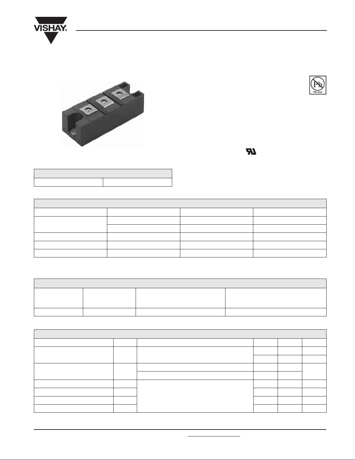
HEXFRED® Ultrafast Diodes, 100 A
(New INT-A-PAK
TM
Power Modules)
FEATURES
• Electrically isolated: DBC base plate
• 3500 V
isolating voltage
RMS
• Standard JEDEC package
• Simplified mechanical designs, rapid assembly
• High surge capability
• Large creepage distances
New INT-A-PAK
TM
• UL E78996 approved
• Case style New INT-A-PAK
PRODUCT SUMMARY
I
F(AV)
100 A
• Totally lead (Pb)-free
• Designed and qualified for industrial level
MAJOR RATINGS AND CHARACTERISTICS
SYMBOL CHARACTERISTICS VALUES UNITS
I
F(AV) rect
t
rr
V
RRM
T
, T
J
Stg
T
C
100 A
88 °C
200 ns
1200 V
- 40 to 150 °C
RoHS
COMPLIANT
ELECTRICAL SPECIFICATIONS
VOLTAGE RATINGS
V
, MAXIMUM REPETITIVE PEAK
TYPE NUMBER
VSKDU162/12PbF 12 1200 1250
VOLTAGE
CODE
RRM
REVERSE VOLTAGE
V
V
, MAXIMUM NON-REPETITIVE
RSM
PEAK REVERSE VOLTAGE
V
FORWARD CONDUCTION
PARAMETER SYMBOL TEST CONDITIONS TYP. MAX. UNITS
Maximum average forward current
at case temperature
Forward voltage drop V
Reverse recovery time t
Reverse recovery charge Q
Reverse recovery current I
Maximum forward voltage drop dI
Document Number: 94512 For technical questions, contact: ind-modules@vishay.com
Revision: 25-Apr-08 1
I
F(AV)
REC
(rec)M
Rectangular conduction, 50 % duty cycle
IF = 100 A, TJ = 25 °C, tp = 400 µs square wave 2.5 3.2
FM
I
= 160 A, TJ = 25 °C, tp = 400 µs square wave 2.9 3.9
F
rr
rr
IF = 160 A, TJ = 25 °C, - dI/dt = 200 A/µs, VR = 200 V
/dt - 300 A/µs
- 100 A
-88°C
V
150 200 ns
2000 2400 nC
20 22 A
www.vishay.com
Page 2
VSKDU162/12PbF
Vishay High Power Products
HEXFRED® Ultrafast Diodes, 100 A
(New INT-A-PAK
TM
Power Modules)
BLOCKING
PARAMETER SYMBOL TEST CONDITIONS VALUES UNITS
Maximum peak reverse
leakage current
RMS insulation voltage V
I
RRM
INS
TJ = 150 °C 30 mA
50 Hz, circuit to base, all terminals shorted, t = 1 s 3500 V
THERMAL AND MECHANICAL SPECIFICATIONS
PARAMETER SYMBOL TEST CONDITIONS VALUES UNITS
Maximum junction operating and
storage temperature range
Maximum thermal resistance,
junction to case per junction
Typical thermal resistance,
case to heatsink
Mounting
torque ± 10 %
Approximate weight
Case style New INT-A-PAK
to heatsink
busbar
, T
T
J
Stg
R
thJC
R
thCS
DC operation 0.18
Mounting surface, flat, smooth and greased 0.05
A mounting compound is recommended and the
torque should be rechecked after a period of 3 hours
to allow the spread of the compound.
- 40 to 150 °C
4 to 6 Nm
200 g
7.1 oz.
K/W
www.vishay.com For technical questions, contact: ind-modules@vishay.com
2 Revision: 25-Apr-08
Document Number: 94512
Page 3

VSKDU162/12PbF
HEXFRED® Ultrafast Diodes, 100 A
(New INT-A-PAK
1000
(A)
F
100
10
Instantaneous Forward Current - I
1
012345678
Fig. 1 - Maximum Forward Voltage Drop Characteristics
Tj = 150˚C
Tj = 25˚C
Forward Voltage Drop - V FM (V)
TM
Power Modules)
Vishay High Power Products
100
T = 150˚C
J
10
(mA)
R
1
0.1
DC
25˚C
F(AV)
0
(A)
0.01
Reverse Current - I
0.001
200 400 600 800 1000 1200
Reverse Voltage - V R (V)
Fig. 2 - Typical Values of Reverse Current vs.
Reverse Voltage
160
140
120
100
80
60
Square wave (D = 0.50)
40
20
Allowable Case Temperature (°C)
0
0408012016020
Average Forward Current - I
Fig. 3 - Maximum Allowable Case Temperature vs.
Average Forward Current
1
D = 0.75
D = 0.50
(°C/W)
thJC
Thermal Impedance - Z
0.0001
D = 0.33
D = 0.25
0.1
D = 0.20
P
0.01
0.001
0.00001 0.0001 0.001 0.01 0.1 1 10
Single Pulse
(Thermal Resistance)
t1, Rectangular Pulse Duration (Seconds)
Fig. 4 - Maximum Thermal Impedance Z
Notes:
1. Duty factor D = t / t
2. Peak Tj = Pdm x ZthJC + Tc
Characteristics
thJC
DM
t
1
t
2
Document Number: 94512 For technical questions, contact: ind-modules@vishay.com
www.vishay.com
Revision: 25-Apr-08 3
Page 4

VSKDU162/12PbF
Vishay High Power Products
900
D = 0.20
800
D = 0.25
D = 0.33
700
D = 0.50
600
D = 0.75
500
400
300
200
Average Power Loss (Watts)
100
0
0 50 100 150 200 25
Average Forward Current - I
Fig. 5 - Forward Power Loss Characteristics
RMS Limit
DC
F(AV)
HEXFRED® Ultrafast Diodes, 100 A
(New INT-A-PAK
0
(A)
TM
Power Modules)
10000
(nC)
1000
RR
Q
100
Fig. 7 - Typical Reverse Recovery Charge vs.dI
Vr = 200V
If = 160A, Tj = 25˚C
dif/ dt - (A/µs)
(Per Leg)
0001001
/dt
F
1000
Vr = 200V
(ns)
rr
t
If = 160A, Tj = 25˚C
100
dif/ dt - (A/µs)
Fig. 6 - Typical Reverse Recovery Time vs. dI
(Per Leg)
100
Vr = 200V
(A)
RR
I
If = 160A, Tj = 25˚C
0001001
/dt
F
10
dif/ dt - (A/µs)
Fig. 8 - Typical Reverse Recovery Current vs. dI
(Per Leg)
0001001
/dt
F
www.vishay.com For technical questions, contact: ind-modules@vishay.com
4 Revision: 25-Apr-08
Document Number: 94512
Page 5

VSKDU162/12PbF
HEXFRED® Ultrafast Diodes, 100 A
(New INT-A-PAK
ORDERING INFORMATION TABLE
Device code
CIRCUIT CONFIGURATION
VS K DU 162 / 12 PbF
- Vishay HPP
1
- K = New INT-A-PAK module
2
- DU = HEXFRED® ultrafast diode
3
- Current rating
4
- Voltage rating (12 = 1200 V)
5
- PbF = Lead (Pb)-free
6
TM
Power Modules)
(1)
~
Vishay High Power Products
51324
6
+
(2)
-
(3)
LINKS TO RELATED DOCUMENTS
Dimensions http://www.vishay.com/doc?95254
Document Number: 94512 For technical questions, contact: ind-modules@vishay.com
Revision: 25-Apr-08 5
www.vishay.com
Page 6

Legal Disclaimer Notice
Vishay
Disclaimer
All product specifications and data are subject to change without notice.
Vishay Intertechnology, Inc., its affiliates, agents, and employees, and all persons acting on its or their behalf
(collectively, “Vishay”), disclaim any and all liability for any errors, inaccuracies or incompleteness contained herein
or in any other disclosure relating to any product.
Vishay disclaims any and all liability arising out of the use or application of any product described herein or of any
information provided herein to the maximum extent permitted by law. The product specifications do not expand or
otherwise modify Vishay’s terms and conditions of purchase, including but not limited to the warranty expressed
therein, which apply to these products.
No license, express or implied, by estoppel or otherwise, to any intellectual property rights is granted by this
document or by any conduct of Vishay.
The products shown herein are not designed for use in medical, life-saving, or life-sustaining applications unless
otherwise expressly indicated. Customers using or selling Vishay products not expressly indicated for use in such
applications do so entirely at their own risk and agree to fully indemnify Vishay for any damages arising or resulting
from such use or sale. Please contact authorized Vishay personnel to obtain written terms and conditions regarding
products designed for such applications.
Product names and markings noted herein may be trademarks of their respective owners.
Document Number: 91000 www.vishay.com
Revision: 18-Jul-08 1
 Loading...