

Vishay VS-60EPU06PbF, VS-60APU06PbF Data Sheet
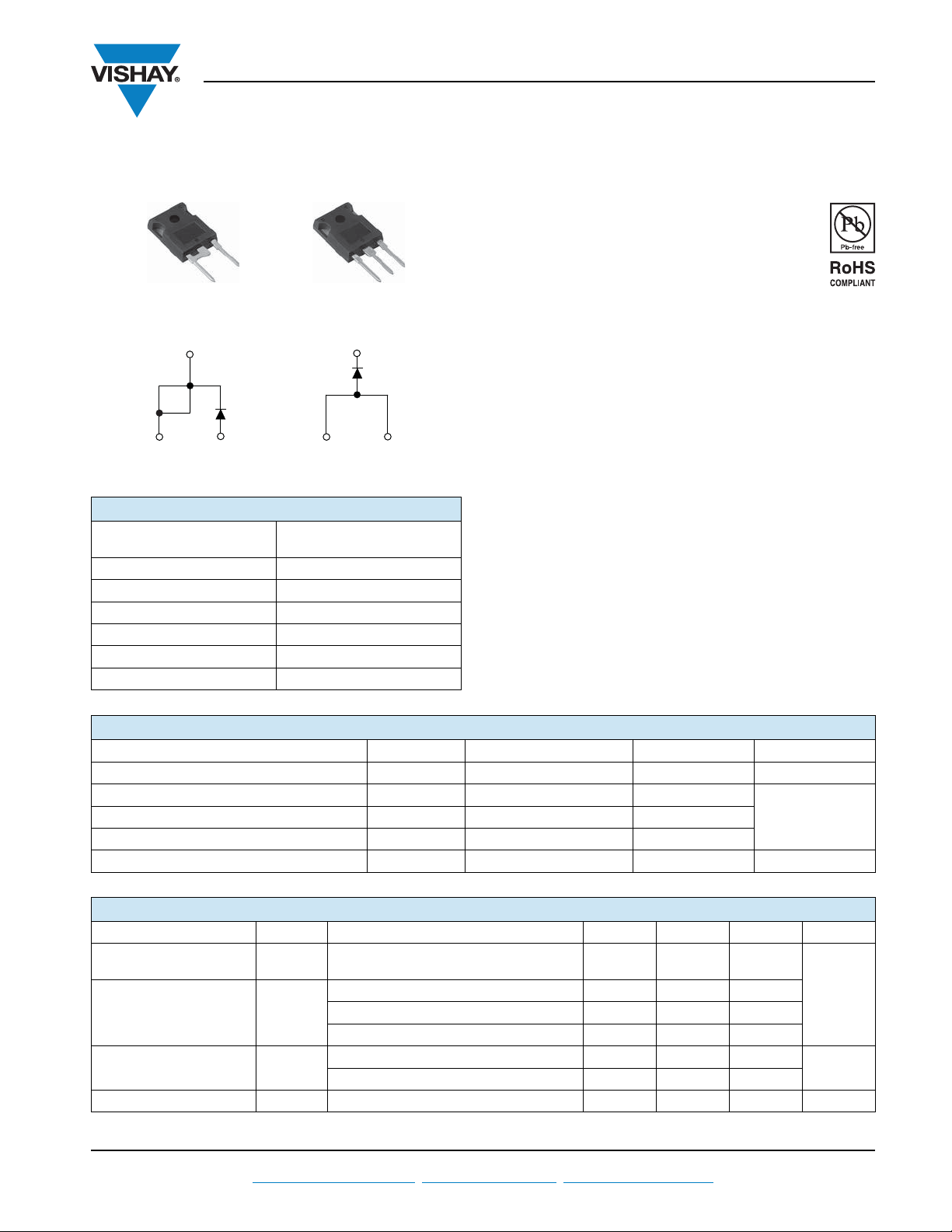
TO-247AC modified
TO-247AC
Cathode
to base
2
1
3
Cathode
Anode
VS-60EPU06PbF
Cathode
to base
2
Anode Anode
VS-60APU06PbF
1
3
VS-60EPU06PbF, VS-60APU06PbF
Vishay Semiconductors
Ultrafast Soft Recovery Diode, 60 A FRED Pt
PRODUCT SUMMARY
Package
I
F(AV)
V
R
V
at I
F
F
typ. See Recovery table
t
rr
T
max. 175 °C
J
Diode variation Single die
TO-247AC modified (2 pins)
TO-247AC,
60 A
600 V
1.68 V
®
FEATURES
• Ultrafast recovery time
• Low forward voltage drop
• 175 °C operating junction temperature
• Compliant to RoHS Directive 2002/95/EC
• Designed and qualified for industrial level
BENEFITS
• Reduced RFI and EMI
• Higher frequency operation
• Reduced snubbing
• Reduced parts count
DESCRIPTION/APPLICATIONS
These diodes are optimized to reduce losses and EMI/RFI in
high frequency power conditioning systems.
The softness of the recovery eliminates the need for a
snubber in most applications. These devices are ideally
suited for HF welding, power converters and other
applications where switching losses are not significant
portion of the total losses.
ABSOLUTE MAXIMUM RATINGS
PARAMETER SYMBOL TEST CONDITIONS MAX. UNITS
Cathode to anode voltage V
Continuous forward current I
Maximum repetitive forward current I
Operating junction and storage temperatures T
ELECTRICAL SPECIFICATIONS (TJ = 25 °C unless otherwise specified)
PARAMETER SYMBOL TEST CONDITIONS MIN. TYP. MAX. UNITS
Breakdown voltage,
blocking voltage
Forward voltage V
Reverse leakage current I
Junction capacitance C
Document Number: 94023 For technical questions within your region, please contact one of the following: www.vishay.com
Revision: 14-Feb-11 DiodesAmericas@vishay.com
R
F(AV)
FSM
FRM
, T
J
Stg
,
V
BR
V
R
IR = 100 μA 600 - -
R
IF = 60 A - 1.35 1.68
I
F
T
= 60 A, TJ = 125 °C - 1.20 1.42
F
= 60 A, TJ = 175 °C - 1.11 1.30
I
F
VR = VR rated - - 50
T
= 150 °C, VR = VR rated - - 500
J
VR = 600 V - 39 - pF
, DiodesAsia@vishay.com, DiodesEurope@vishay.com 1
TC = 116 °C 60
TC = 25 °C 600
Square wave, 20 kHz 120
600 V
ASingle pulse forward current I
- 55 to 175 °C
V
μA

VS-60EPU06PbF, VS-60APU06PbF
Vishay Semiconductors
Ultrafast Soft Recovery Diode,
60 A FRED Pt
®
DYNAMIC RECOVERY CHARACTERISTICS (TJ = 25 °C unless otherwise specified)
PARAMETER SYMBOL TEST CONDITIONS MIN. TYP. MAX. UNITS
IF = 1 A, dIF/dt = 200 A/μs, VR = 30 V - 34 45
Reverse recovery time t
Peak recovery current I
Reverse recovery charge Q
rr
RRM
= 25 °C
J
T
= 125 °C - 164 -
J
TJ = 25 °C - 7.4 -
T
= 125 °C - 17.0 -
J
rr
TJ = 25 °C - 300 -
T
= 125 °C - 1394 -
J
= 60 A
I
F
dI
/dt = 200 A/μs
F
= 200 V
V
R
-81-
THERMAL - MECHANICAL SPECIFICATIONS
PARAMETER SYMBOL TEST CONDITIONS MIN. TYP. MAX. UNITS
Thermal resistance,
junction to case
Thermal resistance,
case to heatsink
Weight
Mounting torque
Marking device
R
- - 0.63
thJC
R
thCS
Mounting surface, flat, smooth
and greased
Case style TO-247AC modified 60EPU06
Case style TO-247AC 60APU06
-0.2-
-5.5- g
-0.2-oz.
1.2
(10)
-
2.4
(20)
(lbf in)
nsT
A
nC
K/W
N m
www.vishay.com For technical questions within your region, please contact one of the following: Document Number: 94023
2 DiodesAmericas@vishay.com
, DiodesAsia@vishay.com, DiodesEurope@vishay.com Revision: 14-Feb-11
1
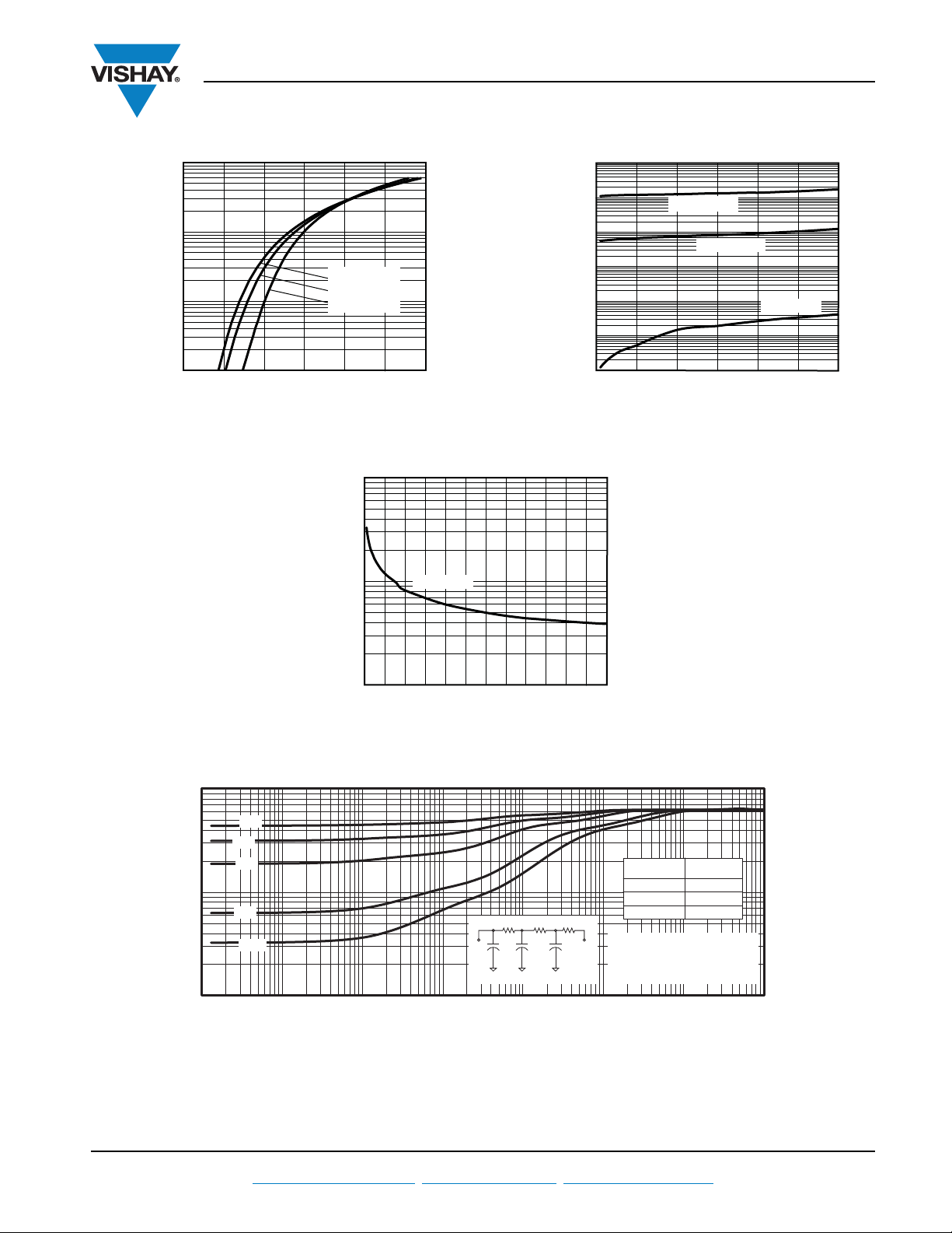
10
1000
0 2.51.5
1.0
VF - Forward Voltage Drop (V)
I
F
- Instantaneous
Forward Current (A)
100
0.5 2.0
TJ = 175 °C
T
J
= 125 °C
T
J
= 25 °C
3.0
100
1000
0 500 600
10
VR - Reverse Voltage (V)
C
T
- Junction Capacitance (pF)
200
TJ = 25 °C
300 400100
0.01
0.1
1
0.00001 0.0001 0.001 0.01 0.1 1
ton - Rectangular Pulse Duration (s)
Z
thJC
- Thermal Impedance (°C/W)
10 100
0.7
0.5
0.3
0.1
0.05
0.06226
0.32503
0.24271
0.00049
0.01294
0.24310
Ri (°C/W)
τi (s)
τ
1
T
J
R1R2R
3
T
C
τ2τ
3
Ci = τi/Ri
Notes:
1. Duty factor D = t
on
/period
2. Peak T
J
= PDM x Z
thJC
+ T
C
VS-60EPU06PbF, VS-60APU06PbF
Ultrafast Soft Recovery Diode,
60 A FRED Pt
®
1000
100
10
1
0.1
- Reverse Current (µA)
R
0.01
I
0.001
0 200
Vishay Semiconductors
TJ = 175 °C
TJ = 125 °C
TJ = 25 °C
100
400300
600500
VR - Reverse Voltage (V)
Fig. 1 - Typical Forward Voltage Drop Characteristics Fig. 2 - Typical Values of Reverse Current vs.
Reverse Voltage
Fig. 3 - Typical Junction Capacitance vs. Reverse Voltage
Document Number: 94023 For technical questions within your region, please contact one of the following: www.vishay.com
Revision: 14-Feb-11 DiodesAmericas@vishay.com
Fig. 4 - Maximum Thermal Impedance Z
Characteristics
thJC
, DiodesAsia@vishay.com, DiodesEurope@vishay.com 3
 Loading...