

VISHAY VLMPG33N1P2, VLMYG33P1Q2 Technical data
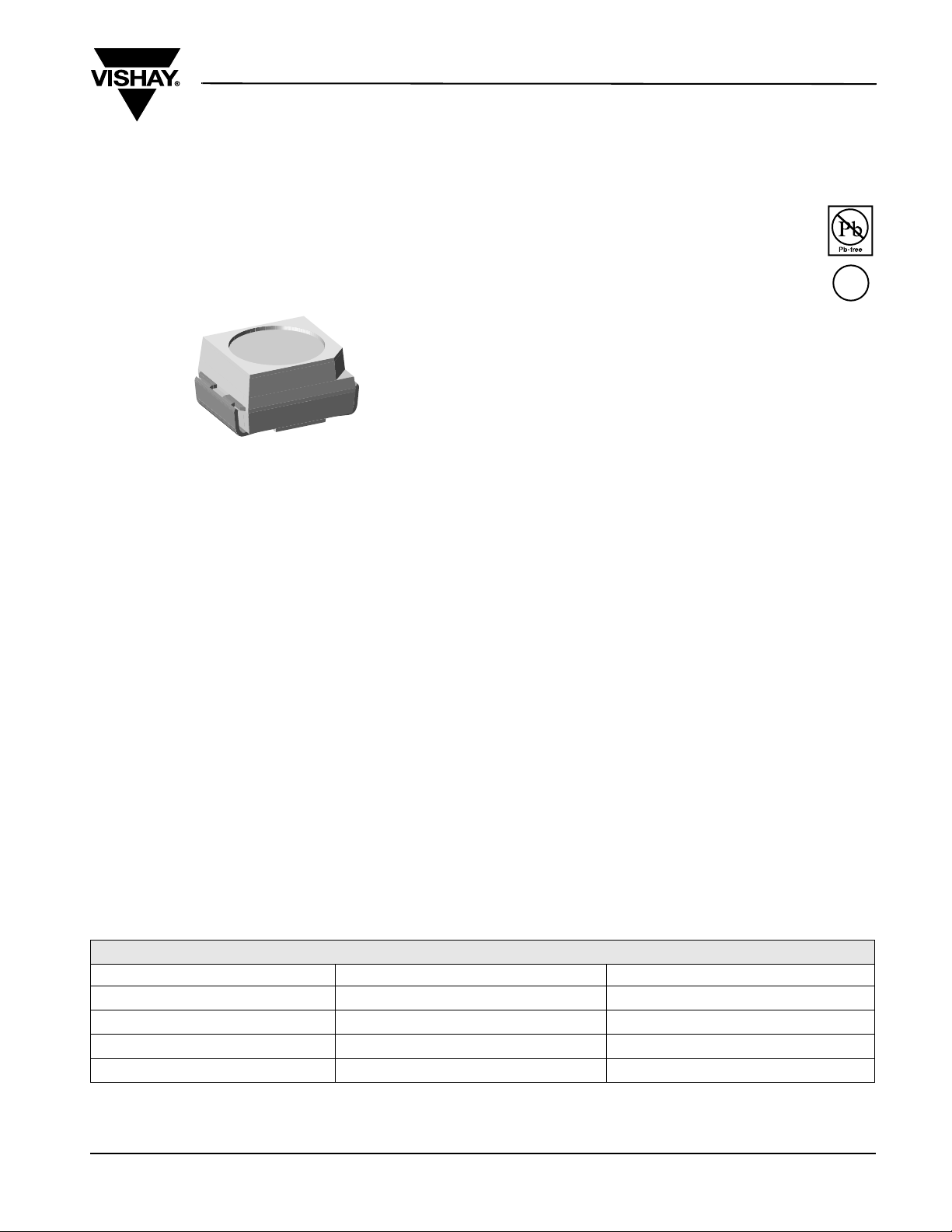
Power SMD LED PLCC-2
19225
DESCRIPTION
The package of the VLM.G33.. is the PLCC-2.
It consists of a lead frame which is embedded in a
white thermoplast. The reflector inside this package is
filled up with clear epoxy.
PRODUCT GROUP AND PACKAGE DATA
• Product group: LED
• Package: SMD PLCC-2
• Product series: power
• Angle of half intensity: ± 60°
VLMPG33N1P2/VLMYG33P1Q2
Vishay Semiconductors
FEATURES
• SMD LED with exceptional brightness
• Luminous intensity categorized
• Compatible with automatic placement
equipment
• EIA and ICE standard package
• Compatible with IR reflow, vapor phase and wave
solder processes according to CECC 00802 and
J-STD-020C
• Available in 8 mm tape
• Low profile package
• Non-diffused lens: excellent for coupling to light
pipes and backlighting
• Low power consumption
• Luminous intensity ratio in one packaging unit
I
Vmax/IVmin
≤ 1.6
• Lead (Pb)-free device
• Preconditioning: acc. to JEDEC level 2a
• Component in accordance to RoHS 2002/95/EC
and WEEE 2002/96/EC
•
ESD-withstand voltage:
up to 2 kV according to JESD22-A114-B
APPLICATIONS
• Automotive: backlighting in dashboards and
switches
• Telecommunication: indicator and backlighting in
telephone and fax
• Indicator and backlight for audio and video
equipment
• Indicator and backlight in office equipment
• Flat backlight for LCDs, switches and symbols
• General use
e3
PARTS TABLE
PART COLOR, LUMINOUS INTENSITY TECHN OLO GY
VLMPG33N1P2-GS08
VLMPG33N1P2-GS18
VLMYG33P1Q2-GS08
VLMYG33P1Q2-GS18
Document Number 81335
Rev. 1.2, 10-Sep-07
Pure green, I
Pure green, I
Yellow green, I
Yellow green, I
= (28 to 71) mcd
V
= (28 to 71) mcd
V
= (45 to 112) mcd
V
= (45 to 112) mcd
V
AlInGaP on GaAs
AlInGaP on GaAs
AlInGaP on GaAs
AlInGaP on GaAs
www.vishay.com
1
VLMPG33N1P2/VLMYG33P1Q2
Vishay Semiconductors
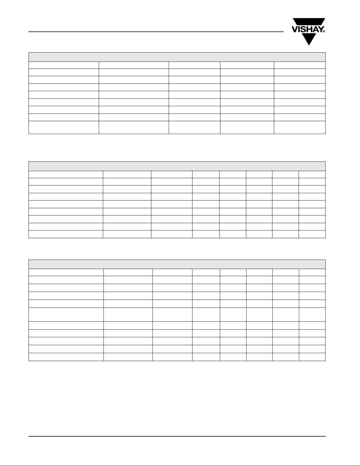
ABSOLUTE MAXIMUM RATINGS
1)
VLMPG33../VLMYG33..
PARAMETER TEST CONDITION SYMBOL VAL UE UNIT
Reverse voltage
DC Forward current
Surge forward current
2)
≤ 73 °C I
T
amb
≤ 10 µs I
t
p
Power dissipation
Junction temperature
Operating temperature range
Storage temperature range
Thermal resistance junction/
ambient
Note:
1)
T
= 25 °C unless otherwise specified
amb
2)
Driving LED in reverse direction is suitable for short term application
mounted on PC board
(pad size > 16 mm
2
)
FSM
T
T
R
V
P
T
amb
stg
thJA
R
F
5V
50 mA
0.2 A
V
j
130 mW
125 °C
- 40 to + 100 °C
- 40 to + 100 °C
400 K/W
OPTICAL AND ELECTRICAL CHARACTERISTICS1) VLMPG33.., PURE GREEN
PARAMETER TEST CONDITION PART SYMBOL MIN TYP MAX UNIT
= 30 mA VLMPG33N1P2 I
Luminous intensity
Dominant wavelength
Peak wavelength
Angle of half intensity
Forward voltage
Reverse voltage
Temperature coefficient of V
Temperature coefficient of I
Note:
1)
T
= 25 °C unless otherwise specified
amb
I
F
= 30 mA λ
I
F
= 30 mA λ
I
F
= 30 mA
I
F
I
= 30 mA V
F
= 10 µA V
I
R
F
V
IF = 30 mA TC
IF = 30 mA TC
V
d
p
ϕ ± 60 deg
F
R
V
I
28 71 mcd
555 560 565 nm
565 nm
22.5V
5V
- 4 mV/K
- 0.4 %/K
OPTICAL AND ELECTRICAL CHARACTERISTICS1) VLMYG33.., YELLOW GREEN
PARAMETER TEST CONDITION PART SYMBOL MIN TYP. MAX UNIT
= 30 mA VLMYG33P1Q2 I
Luminous intensity
Luminous flux/luminous intensity
Dominant wavelength
Peak wavelength
Spectral bandwidth
at 50 % I
rel max
Angle of half intensity
Forward voltage
Reverse voltage
Temperature coefficient of V
Temperature coefficient of I
Note:
1)
T
= 25 °C unless otherwise specified
amb
I
F
= 30 mA λ
I
F
= 30 mA λ
I
F
IF = 30 mA
= 30 mA
I
F
I
= 30 mA V
F
= 10 µA V
I
R
F
V
IF = 30 mA T
IF = 30 mA T
V
φ
V/IV
d
p
Δλ 18 nm
ϕ ± 60 deg
F
R
CV
CI
45 112 mcd
3mlm/mcd
566 577 nm
1.7 2.0 2.5 V
5V
- 4 mV/K
- 0.04 %/K
nm
www.vishay.com
2
Document Number 81335
Rev. 1.2, 10-Sep-07
VLMPG33N1P2/VLMYG33P1Q2
Vishay Semiconductors
LUMINOUS INTENSITY CLASSIFICATION
GROUP LUMINOUS INTENSITY (MCD)
STANDARD OPTIONAL MIN MAX
L
M
N
P
Q
Note:
Luminous intensity is tested at a current pulse duration of 25 ms and
an accuracy of ± 11 %.
The above type Numbers represent the order groups which include
only a few brightness groups. Only one group will be shipped on
each reel (there will be no mixing of two groups on each reel).
In order to ensure availability, single brightness groups will not be
orderable.
In a similar manner for colors where wavelength groups are
measured and binned, single wavelength groups will be shipped on
any one reel.
In order to ensure availability, single wavelength groups will not be
orderable.
1 11.2 14.0
2 14.0 18.0
1 18.0 22.4
2 22.4 28.0
1 28.0 35.5
2 35.5 45.0
1 45.0 56.0
2 56.0 71.0
1 71.0 90.0
2 90.0 112.0
COLOR CLASSIFICATION
DOMINANT WAVELENGTH (NM)
GROUP
PURE GREEN YELLOW GREEN
MIN MAX MIN MAX
0 555 559
1 558 561
2 560 563
3 562 565
4
5 566 569
6 568 571
7 570 573
8 572 575
9 574 577
Note:
Wavelengths are tested at a current pulse duration of 25 ms and an
accuracy of ± 1 nm.
CROSSING TABLE
VISHAY OSRAM
VLMPG33N1P2 LPT675N1P2
VLMYG33P1Q2 LGT676
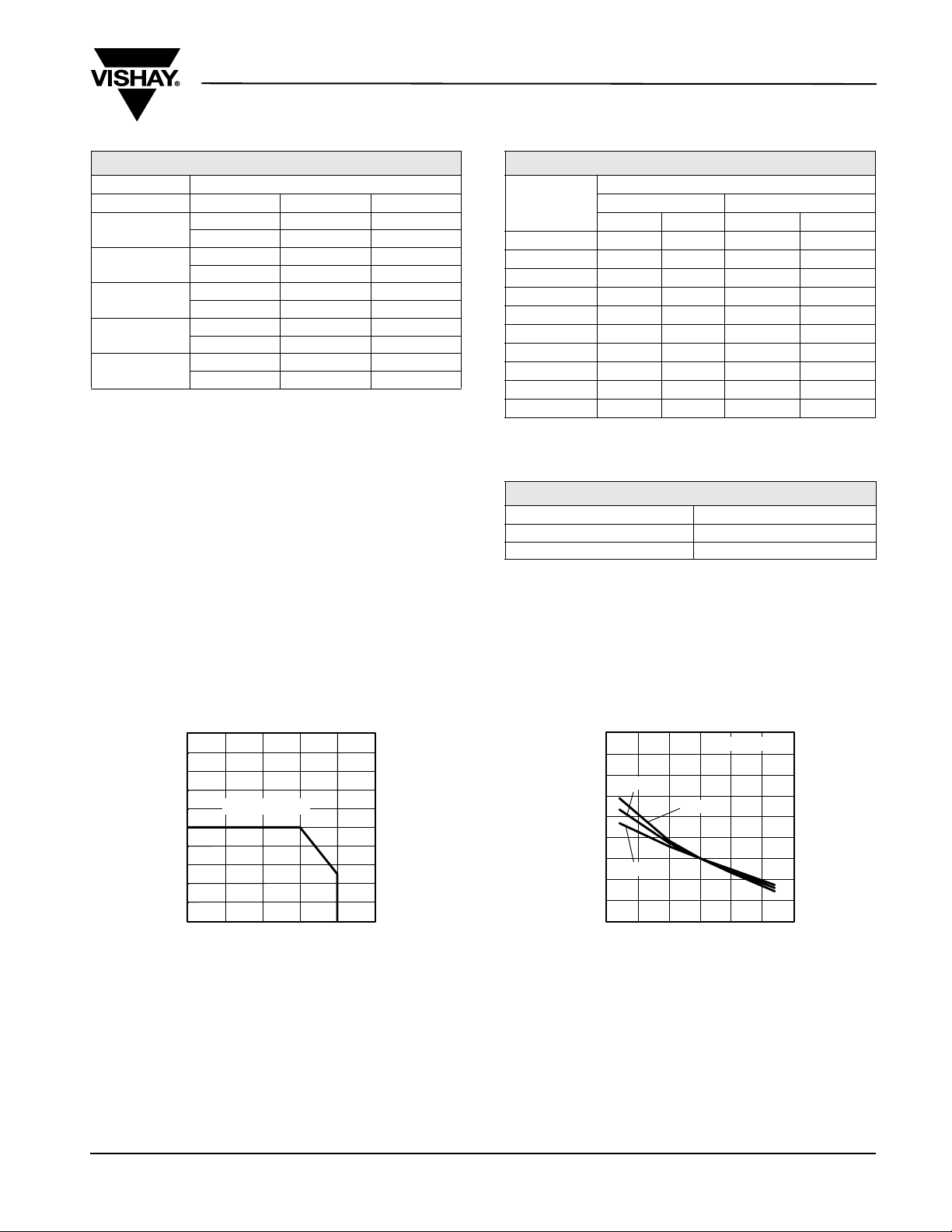
TYPICAL CHARACTERISTICS
T
= 25 °C, unless otherwise specified
amb
100
90
80
70
R
60
50
40
30
20
- Forward Current (mA)
F
I
10
0
10 25 50 75 100 125
16784
T
Figure 1. Forward Current vs. Ambient Temperature
= 400 K/W
thJA
- Ambient Temperature (°C)
amb
600
500
400
30 mA
300
200
100
0
10 mA
- 100
- 200
- Change of Forward Voltage (mV)
F
V
- 300
Δ
- 50 - 25 0 25 50 75 100
T
18615
- Ambient Temperature (°C)
amb
pure green
50 mA
Figure 2. Change of Forward Voltage vs. Ambient Temperature
Document Number 81335
Rev. 1.2, 10-Sep-07
www.vishay.com
3
 Loading...