

Bulletin PD-20624 05/01
A
STPS40L40CW
SCHOTTKY RECTIFIER 40 Amp
Major Ratings and Characteristics Description/Features
The STPS40L40CW center tap Schottky rectifier has been
Characteristics Value Units
I
Rectangular 40 A
F(AV)
waveform
V
RRM
I
@ tp = 5 µs sine 3500 A
FSM
VF@ 20 Apk, TJ=125°C 0.43 V
(per leg)
T
J
20.30 (0 .800)
19.70 (0 .775)
14. 80 ( 0. 583)
14. 20 (0 . 559 )
1.40 (0 .05 6)
1.00 (0 .03 9)
10.94 ( 0.430)
10.86 (0 .427)
40 V
- 55 to 150 °C
15.90 (0.626)
15.30 (0.602)
12 3
4. 30 (0 . 17 0)
3.70 (0 .14 5)
3.65 (0 .144)
3.55 (0 .13 9)
5.70 (0 .225)
5.30 ( 0.208)
2. 20 (0 . 08 7)
MAX.
5.50 ( 0.217)
4. 50 (0 .1 7 7)
(2 PLCS.)
optimized for very low forward voltage drop, with moderate
leakage. The proprietary barrier technology allows for reliable
operation up to 150° C junction temperature. Typical applications are in switching power supplies, converters, free-wheeling diodes, and reverse battery protection.
150° C TJ operation
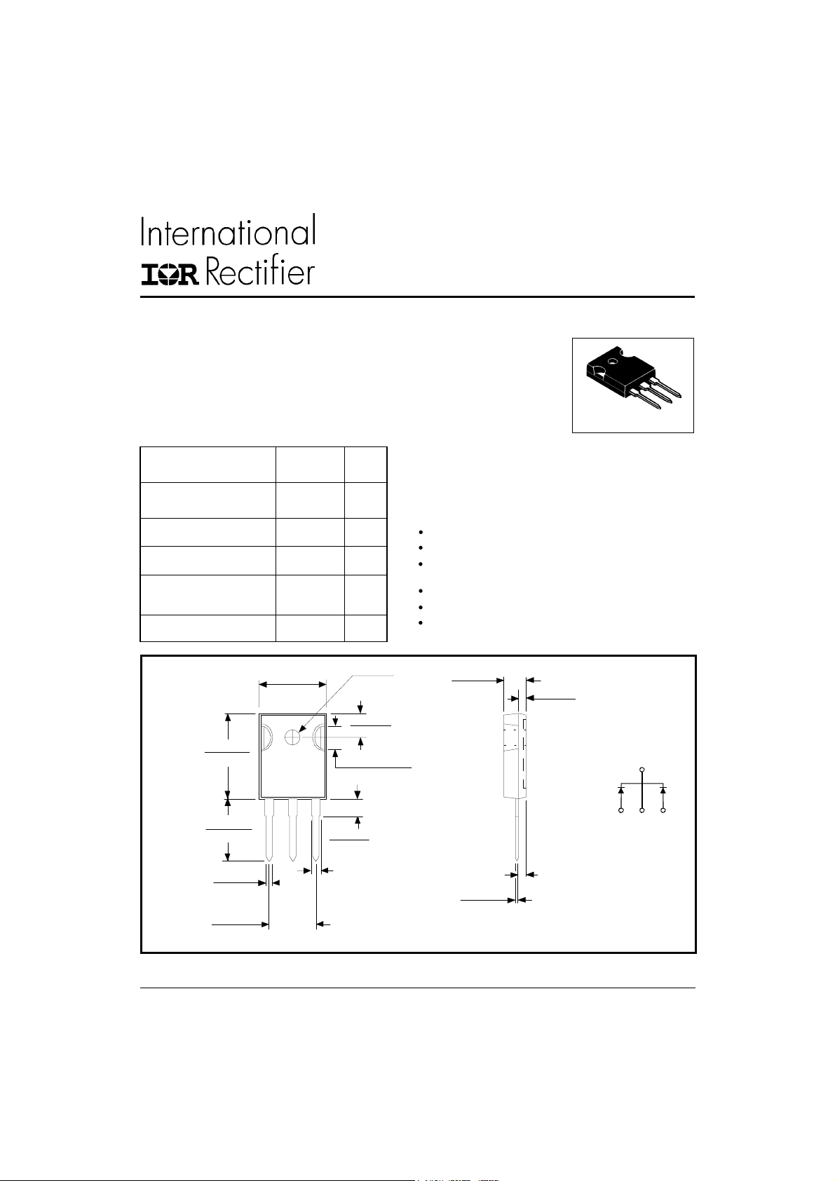
Center tap TO-247 package
High purity, high temperature epoxy encapsulation for
enhanced mechanical strength and moisture resistance
Very low forward voltage drop
High frequency operation
Guard ring for enhanced ruggedness and long term
reliability
DIA.
5. 30 (0 .2 0 9)
4.70 ( 0.185)
0.80 ( 0.032)
0. 40 (0 .2 1 3)
Conform to JEDEC outline TO-247AC (TO-3P)
Dimensions in millimeters and inches
2.5 ( 0. 098)
1.5 (0. 059)
2. 40 (0 .0 9 5)
MAX.
TO-247AC
BASE
COMMON
CATHODE
2
123
COMMON
NODE
ANODE
CATHODE
12
1
www.irf.com
STPS40L40CW
Bulletin PD-20624 05/01
Voltage Ratings
Part number STPS40L40CW
VRMax. DC Reverse Voltage (V)
V
Max. Working Peak Reverse Voltage (V)
RWM
40
Absolute Maximum Ratings
Parameters Value Units Conditions
I
Max. Average Forward Current 40 A 50% duty cycle @ TC = 120 °C, rectangular wave form
F(AV)
* See Fig. 5
I
Max. Peak One Cycle Non-Repetitive 3500 5µs Sine or 3µs Rect. pulse
FSM
Surge Current (Per Leg) * See Fig. 7 430 10ms Sine or 6ms Rect. pulse
EASNon-Repetitive Avalanche Energy 27 mJ T
(Per Leg)
A
= 25 °C, I
J
= 4 Amps, L = 3.4 mH
AS
IARRepetitive Avalanche Current 4 A Current decaying linearly to zero in 1 µsec
(Per Leg) Frequency limited by TJ max. VA = 1.5 x VR typical
Following any rated
load condition and with
rated V
RRM
applied
Electrical Specifications
Parameters Value Units Conditions
VFMMax. Forward Voltage Drop 0.49 V @ 20A
(Per Leg) * See Fig. 1 (1) 0.59 V @ 40A
0.43 V @ 20A
0.56 V @ 40A
IRMMax. Reverse Leakage Current 0.8 mA TJ = 25 °C
(Per Leg) * See Fig. 2 (1) 60 mA TJ = 100 °C
CTMax. Junction Capacitance (Per Leg) 1850 pF VR = 5VDC, (test signal range 100Khz to 1Mhz) 25°C
LSTypical Series Inductance (Per Leg) 7.5 nH Measured lead to lead 5mm from package body
dv/dt Max. Voltage Rate of Change 10000 V/ µs
(Rated VR)
TJ = 25 °C
TJ = 125 °C
VR = rated V
(1) Pulse Width < 300µs, Duty Cycle <2%
R
Thermal-Mechanical Specifications
Parameters Value Units Conditions
TJMax. Junction Temperature Range -55 to 150 °C
T
Max. Storage Temperature Range -55 to 150 °C
stg
R
Max. Thermal Resistance Junction 1.25 °C/W DC operation * See Fig. 4
thJC
to Case (Per Leg)
R
Max. Thermal Resistance Junction 0.63 °C/W DC operation
thJC
to Case (Per Package)
R
Typical Thermal Resistance, Case 0.24 °C/W Mounting surface , smooth and greased
thCS
to Heatsink
wt Approximate Weight 6 (0.21) g (oz.)
T Mounting Torque Min. 6 (5) Non-lubricated threads
Max. 12 (10)
Kg-cm
(Ibf-in)
Case Style TO-247AC(TO-3P) JEDEC
2
www.irf.com

STPS40L40CW
5
Bulletin PD-20624 05/01
1000
100
F
10
T = 150°C
J
T = 125°C
J
Instantaneous Forward Current - I (A)
1
T = 25°C
J
1000
T = 150°C
J
100
10
R
1
.1
Reverse Current - I (mA)
.01
.001
125°C
100°C
75°C
50°C
25°C
0 5 10 15 20 25 30 35 40 4
Reverse Volt age - V (V)
Fig. 2 - Typical Values Of Reverse Current
Vs. Reverse Voltage (Per Leg)
10000
T
1000
T = 25°C
J
R
.1
0.2.4.6.811.21.4
Fig. 1 - Max. Forward Voltage Drop Characteristics
www.irf.com
Junct ion Capacit ance - C (pF)
100
0 1020304050
Forward Volt age Drop - V (V)
FM
Reverse Voltage - V (V)
Fig. 3 - Typical Junction Capacitance
(Per Leg)
10
1
D = 0 .5 0
thJC
Thermal Impedance - Z (°C/W)
D = 0 .3 3
D = 0 .2 5
D = 0 .1 7
.1
D = 0 .0 8
.01
Singl e Pulse
(Thermal Resistance)
.001
.0 0001 . 0001 . 001 . 01 .1 1 10 100
t , Rectangular Pulse Durati on (Seconds)
1
Fig. 4 - Max. Thermal Impedance Z
thJC
Notes:
1. Duty factor D = t / t
2. Peak T = P x Z + T
Characteristics (Per Leg)
Vs. Reverse Voltage (Per Leg)
P
DM
t
1
t
2
JDM
1
thJC
R
2
C
3

STPS40L40CW
Bulletin PD-20624 05/01
155
R (DC) = 1.25°C/ W
150
145
140
135
Al l owa bl e Cas e Te mperature - (°C)
130
0 5 10 15 20 25 30
Average Forward Current - I (A)
thJC
DC
Fig. 5 - Max. Allowable Case Temperature
Vs. Average Forward Current (Per Leg)
Non-Repetitive Surge Current - I (A)
14
D = 0.08
D = 0.17
12
D = 0.25
D = 0.33
10
D = 0.50
8
RMS Li mit
6
4
Average Power Loss - (Watts)
2
0
0 5 10 15 20 25 30
F( AV)
Fig. 6 - Forward Power Loss Characteristics
10000
FSM
1000
At Any Rated Load Condition
And With Rated V Applied
Following Surge
100
10 100 1000 10000
Square Wave Pulse Duration - t (microsec)
RRM
p
Fig. 7 - Max. Non-Repetitive Surge Current (Per Leg)
DC
Average For ward Current - I (A)
F(AV)
(Per Leg)
L
HIGH-SPEED
SW IT C H
FREE-WHE EL
D IO D E
40HFL40S02
Vd = 25 Volt
+
CURRENT
MONITOR
DUT
IRFP460
Rg = 25 ohm
Fig. 8 - Unclamped Inductive Test Circuit
4
www.irf.com

STPS40L40CW
Bulletin PD-20624 05/01
This product has been designed and qualified for Industrial Level.
Data and specifications subject to change without notice.
Qualification Standards can be found on IR's Web site.
IR WORLD HEADQUARTERS: 233 Kansas St., El Segundo, California 90245, USA Tel: (310) 252-7105
TAC Fax: (310) 252-7309
Visit us at www.irf.com for sales contact information. 05/01
www.irf.com
5
 Loading...