

MPM (Divider)
Vishay Thin Film
Molded, SOT-23 Resistor Network
NETWORKS
SURFACE MOUNT
Vishay Thin Film MPM Series Dividers provide ± 2 ppm/°C
tracking and a ratio tolerance as tight as 0.05 %, small size,
and exceptional stability for all surface mount applications.
The standard SOT-23 package format with unity and
common standard resistance divider ratios provide easy
selection for most applications requiring matched pair
resistor elements. The ratios listed are available for off the
shelf delivery. If you require a non-standard ratio, consult the
applications engineering group as we may be able to meet
your requirements with a custom design.
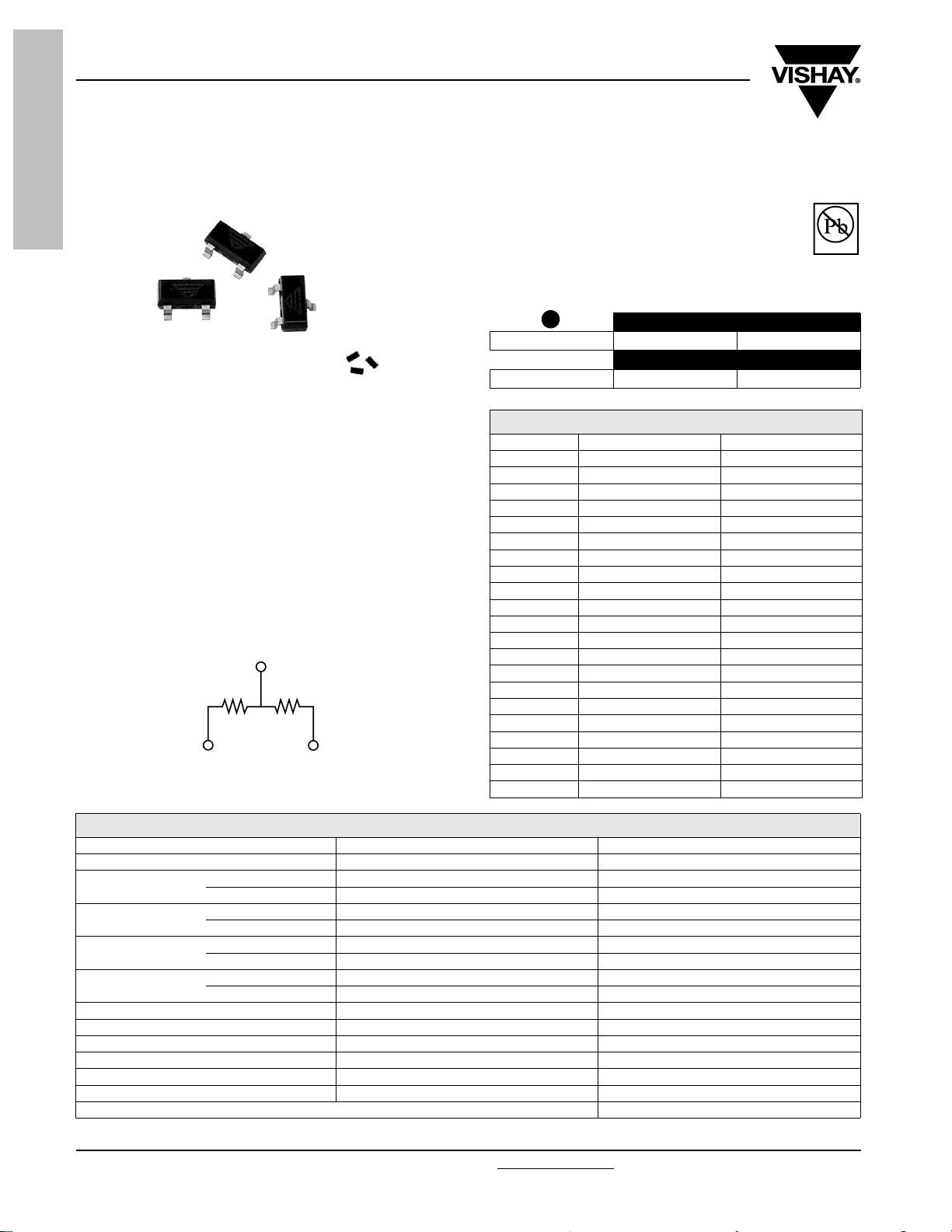
SCHEMATIC
3
1
R
R
1
2
2
Actual Size
FEATURES
• Lead (Pb)-free available
• Stocked
• Standard Footprint
Pb-free
Available
RoHS*
1
(Ω)
COMPLIANT
TYPICAL PERFORMANCE
ABS TRACKING
TCR 25 2
ABS RATIO
TOL 0.1 0.05
STANDARD DIVIDER RATIO (R2/R1)
RATIO R2 (Ω)R
100 : 1 100K 1K
50 : 1 50K 1K
25 : 1 25K 1K
20 : 1 20K 1K
10 : 1 10K 1K
9 : 1 9K 1K
6 : 1 6K 1K
5 : 1 10K 2K
5 : 1 5K 1K
4 : 1 8K 2K
4 : 1 4K 1K
2 : 1 10K 5K
2 : 1 2K 1K
1 : 1 50K 50K
1 : 1 25K 25K
1 : 1 10K 10K
1 : 1 5K 5K
1 : 1 2.5K 2.5K
1 : 1 1K 1K
1 : 1 500 500
1 : 1 250 250
STANDARD ELECTRICAL SPECIFICATIONS
TEST SPECIFICATIONS CONDITION
MATERIAL TAMELOX
TCR:
Tolerance:
Power Rating:
Stability:
Voltage Coefficient 0.1 ppm/Volt
Working Voltage 100 Volts Max. Operating Temperature Range - 55 °C to + 125 °C
Storage Temperature Range - 55 °C to + 125 °C
Noise < - 30 dB
Thermal EMF 0.2 µV/°C
Shelf Life Stability (Ratio) 50 ppm Max. 1 year at + 25 °C
* Pb containing terminations are not RoHS compliant, exemptions may apply
www.vishay.com For technical questions contact thin-film@vishay.com
8 Revision: 14-Jun-06
Tracking ± 2 ppm/°C (typical) - 55 °C to + 125 °C
Absolute ± 25 ppm/°C - 55 °C to + 125 °C
Ratio ± 0.5 % to 0.01 % + 25 °C
Absolute ± 1.0 % to ± 0.05 % + 25 °C
Resistor 100 mW Max. at + 70 °C
Package 200 mW Max. at + 70 °C
ΔR Absolute 0.10 % 2000 hrs at + 70 °C
ΔR Ratio 0.03% 2000 hrs at + 70 °C
Document Number: 60001
Molded, SOT-23 Resistor Network
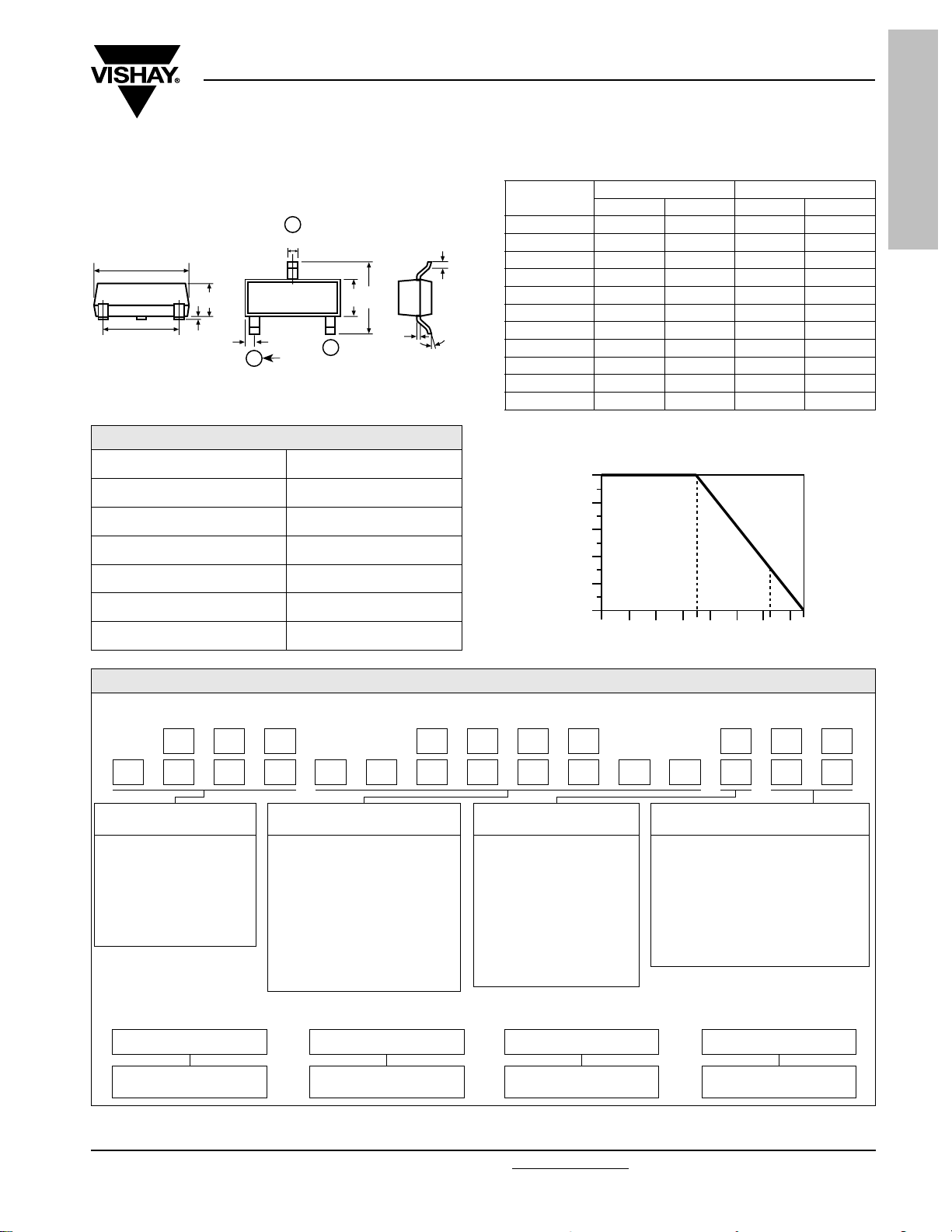
DIMENSIONS AND IMPRINTING in inches and millimeters
MPM (Divider)
Vishay Thin Film
SURFACE MOUNT
NETWORKS
3
W
B
L
A
S
A1
K
Pin #
1
H
2
J
Ø
MECHANICAL SPECIFICATIONS
Resistive Element TAMELOX
Substrate Material Silicon
Body Molded epoxy
Terminals Copper alloy #42 Sn62 plated
Lead Coplanarity 3 Mils Max.
Lead (Pb)-free Option 100 % Sn Matte**
Lead (Pb)-free Finish Plated
DIMENSION
A 0.031 0.040 0.79 1.02
A1 0.001 0.004 0.02 0.10
T
B 0.105 0.120 2.67 3.05
S 0.071 0.079 1.80 2.00
W 0.015 0.021 0.38 0.54
L 0.083 0.098 2.10 2.50
H 0.047 0.055 1.20 1.40
T 0.005 0.010 0.13 0.25
J 0.0035 0.0059 0.089 0.15
K 0.017 0.022 0.44 0.55
Ø08°08°
INCHES MILLIMETERS
MIN. MAX. MIN. MAX.
DERATING CURVE
Percent of Rated Power 100 % = 0.25 W
100
80
60
40
20
0
0
70 125 150
Ambient Temperature °C
GLOBAL PART NUMBER INFORMATION
New Global Part Numbering: MPM1002AWS (preferred part number format)
PM 1003M AWS
PMT25012M 501QT1
GLOBAL MODEL
(3 or 4 digits)
MPM
(Tin Lead)
MPMT
(Lead (Pb)-free)
(e3)
Historical Part Number example: MPM1002BW (will continue to be accepted)
MPM 1002 B W
SERIES RESISTANCE
First 3 digits are significant
figures and the last digit
specifies the number of zeroes
to follow. When like values are
required use total resistance.
When dual values are required
list both values.
Example:
1002 = 10K (5K/5K)
1003 = 100K (50K/50K)
10011002 = 1K/10K divider
RESISTANCE
(4 or 8 digits)
TOLERANCE AND
RATIO TOLERANCE
Abs. Tol.
A = 0.1 %
B = 0.1 %
C = 0.25 %
D = 0.5 %
F = 1 %
*Z = 0.1 %
*Q = 0.05 %
* Tol. Available 1K and up
TOLERANCE AND
RATIO TOLERANCE
Ratio
0.05 %
0.1%
0.1 %
0.1 %
0.5 %
0.25 %
0.01 %
PA CK A GI N G
BS = BULK 100 Min 1 Mult
WS = WAFFLE 100 Min 1 Mult
TAPE AND REEL
T0 = 100 Min 100 Mult
T1 = 1000 Min 1000 Mult
T3 = 300 Min 300 Mult
T5 = 500 Min 500 Mult
TF = Full Reel 2500
TS = 100 Min 1 Mult
PA CK A GI N G
Document Number: 60001 For technical questions contact thin-film@vishay.com
Revision: 14-Jun-06 9
www.vishay.com

Legal Disclaimer Notice
Vishay
Notice
Specifications of the products displayed herein are subject to change without notice. Vishay Intertechnology, Inc.,
or anyone on its behalf, assumes no responsibility or liability for any errors or inaccuracies.
Information contained herein is intended to provide a product description only. No license, express or implied, by
estoppel or otherwise, to any intellectual property rights is granted by this document. Except as provided in Vishay's
terms and conditions of sale for such products, Vishay assumes no liability whatsoever, and disclaims any express
or implied warranty, relating to sale and/or use of Vishay products including liability or warranties relating to fitness
for a particular purpose, merchantability, or infringement of any patent, copyright, or other intellectual property right.
The products shown herein are not designed for use in medical, life-saving, or life-sustaining applications.
Customers using or selling these products for use in such applications do so at their own risk and agree to fully
indemnify Vishay for any damages resulting from such improper use or sale.
Document Number: 91000 www.vishay.com
Revision: 08-Apr-05 1
 Loading...