

Bulletin I2035 rev. B 04/00
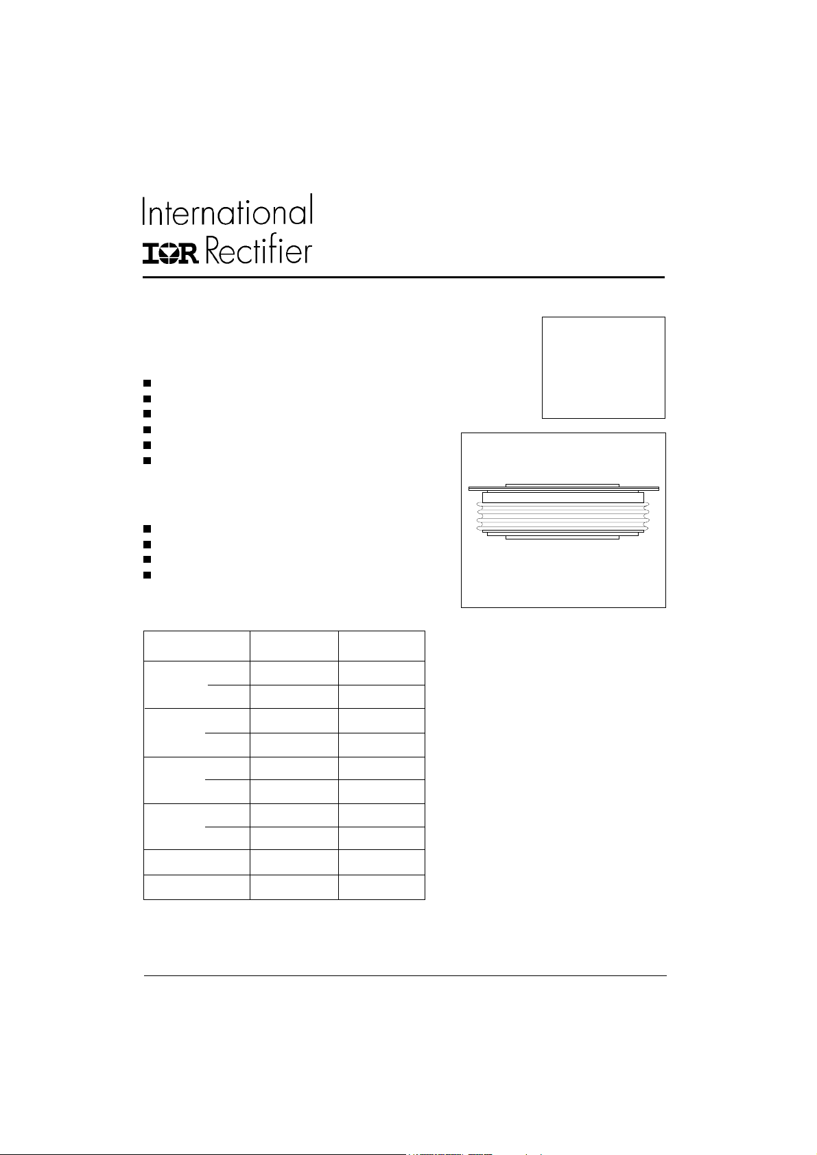
SD6000C..R SERIES
STANDARD RECOVERY DIODES
Features
Wide current range
High voltage ratings up to 2400V
High surge current capabilities
Diffused junction
Hockey Puk version
Case style B-44 (R-PUK)
Typical Applications
Converters
Power supplies
High power drives
Auxiliary system supplies for traction applications
Major Ratings and Characteristics
Parameters SD6000C..R Units
I
F(AV)
I
F(RMS)
I
FSM
@ T
hs
@ T
hs
@ 50Hz 76400 A
@ 60Hz 80000 A
6690 A
55 °C
11150 A
25 °C
Hockey Puk Version
6690A
case style B-44 (R-PUK)
I2t@
V
RRM
T
J
50Hz 29200 KA2s
@ 60Hz 26650 KA2s
range 1200 to 2400 V
- 40 to 175 °C
www.irf.com
1
SD6000C..R Series
Bulletin I2035 rev. B 04/00
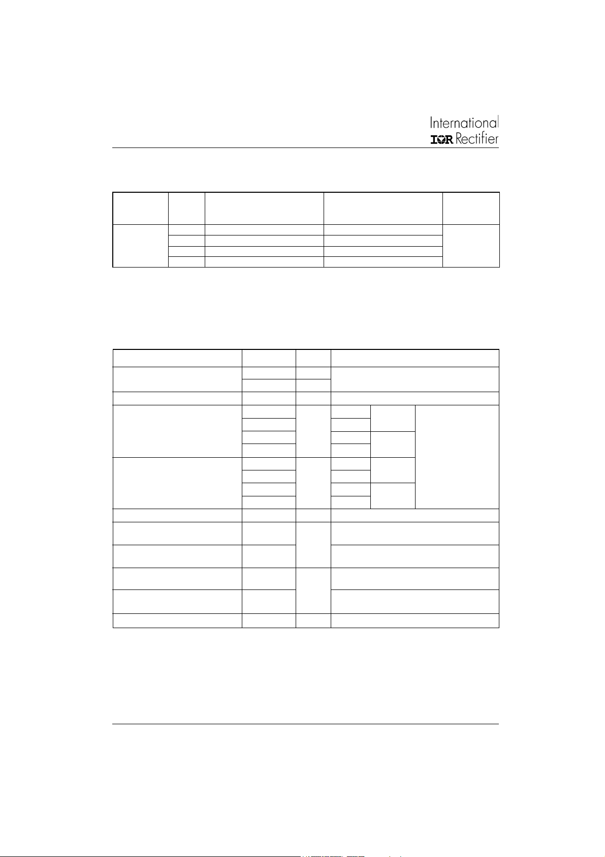
ELECTRICAL SPECIFICATIONS
Voltage Ratings
Voltage V
Type number Code peak reverse voltage repetitive peak rev. voltage @ T
12 1200 1300
SD6000C..R 100
16 1600 1700
20 2000 2100
24 2400 2500
Forward Conduction
Parameter SD6000C..R Units Conditions
I
Max. average forward current 6690 (3520) A 180° conduction, half sine wave
F(AV)
@ Heatsink temperature 55 (85) °C Double side (single side) cooled
I
Max. RMS forward current 11150 A @ 25°C heatsink temperature double side cooled
F(RMS)
I
Max. peak, one-cycle forward, 76400 t = 10ms No voltage
FSM
non-repetitive surge current 80000 t = 8.3ms reapplied
2
I
t Maximum I2t for fusing 29200 t = 10ms No voltage Initial TJ = TJ max.
2
I
√t Maximum I2√t for fusing 292000 KA2√s t = 0.1 to 10ms, no voltage reapplied
Low level value of threshold
V
F(TO)1
voltage
V
High level value of threshold
F(TO)2
voltage
r
Low level value of forward
1
f
slope resistance
r
High level value of forward
2
f
slope resistance
V
Max. forward voltage drop 1.22 V Ipk= 9000A, TJ = TJ max, tp = 10ms sinusoidal wave
FM
, maximum repetitive V
RRM
VVmA
64250 t = 10ms 100% V
67280 t = 8.3ms reapplied Sinusoidal halfwave,
26650 t = 8.3ms reapplied
20640 t = 10ms 100% V
18850 t = 8.3ms reapplied
0.727 (16.7% x π x I
1.350 (I > π x I
0.055 (16.7% x π x I
0.027 (I > π x I
A
KA2s
V
mΩ
, maximum non- I
RSM
RRM
RRM
< I < π x I
F(AV)
),TJ = TJ max.
F(AV)
< I < π x I
F(AV)
),TJ = TJ max.
F(AV)
), TJ = TJ max.
F(AV)
), TJ = TJ max.
F(AV)
RRM
= 175°C
J
max.
2
www.irf.com

Bulletin I2035 rev. B 04/00
Thermal and Mechanical Specifications
Parameter SD6000C..R Units Conditions
TJMax. junction operating temperature range -40 to 175
T
Max. storage temperature range -55 to 200
stg
Max. thermal resistance, junction 0.02 DC operation single side cooled
R
thJ-hs
to heatsink 0.01 DC operation double side cooled
F Mounting force, ± 10% 39200 N
(4000) (Kg)
wt Approximate weight 1590 g
Case style B-44 (R-PUK) See Outline Table
Conduction
∆R
thJ-hs
(The following table shows the increment of thermal resistence R
Conduction angle Units Conditions
180° 0.0009 0.0010 0.0006 0.0006
120° 0.0010 0.0011 0.0010 0.0010
90° 0.0013 0.0013 0.0014 0.0014 K/ W T
60° 0.0019 0.0019 0.0020 0.0020
30° 0.0033 0.0033 0.0034 0.0034
Sinusoidal conduction Rectangular conduction
Single Side Double Side Single Side Double Side
thJ-hs
°C
K/W
when devices operate at different conduction angles than DC)
= TJ max.
J
SD6000C..R Series
Ordering Information Table
Device Code
1 - Diode
2 - Essential part number
3 - 0 = Standard recovery
4 - C = Ceramic Puk
5 - Voltage code: code x 100 = V
6 - R = Puk Case B-44 (R-PUK)
www.irf.com
SD 600 0 C 24 R
1 2
3
4 5
(see Voltage Ratings Table)
RRM
6
3

SD6000C..R Series
Bulletin I2035 rev. B 04/00
Outline Table
3.5 (0.14) DIA. NOM. x
2.5 (0.10) DEEP MIN.
BOTH ENDS
111 (4.37) DIA. MAX.
0.8 (0.03) MIN.
BOTH ENDS
36.2 (1.43)
37.2 (1.46)
180
160
140
120
100
80
60
40
0 10002000300040005000
Maximum Allowable Heatsink Temperature ( C)
Average Forward Current (A)
Fig. 1 - Current Ratings Characteristics
SD6000C..R Series
(Single Side Cooled)
R (DC ) = 0.02 K /W
thJ-hs
30
73.2 (2.88) DIA. MAX.
TWO PLACES
100.5 (3.96) DIA. MAX.
Conduction Angle
60
90
120
180
Case Style B-44
All dimensions in millimeters (inches)
Quote between upper and lower
pole pieces has to be considered
after application of Mounting Force
(see Thermal and Mechanical
Specification)
180
160
140
120
100
80
60
40
20
0 1000200030004000500060007000
Maximum Allowable Heatsink Temperature ( C)
SD6000C..R Series
(Single Side Cooled)
R (D C ) = 0.02 K/W
thJ -hs
Conduction Period
30
60
90
120
180
Average Forward Current (A)
Fig. 2 - Current Ratings Characteristics
DC
4
www.irf.com

SD6000C..R Series
Bulletin I2035 rev. B 04/00
180
160
SD6000C..R Series
(Double Side Cooled)
R (DC ) = 0.01 K/W
thJ -hs
140
120
Conduction Angle
100
80
60
40
0 2000 4000 6000 8000
Maximum Allowable Heatsink Temperature ( C)
Fig. 3 - Current Ratings Characteristics Fig. 4 - Current Ratings Characteristics
30
60
90
120
180
Average Forward Current (A)
14000
12000
180
120
10000
8000
90
60
30
RMS Limit
6000
4000
2000
0
Maximum Average Forward Power Loss (W)
0 2000 4000 6000 8000
Conduction Angle
SD6000C..R Series
T = 175 C
J
Average Forward Current (A)
Fig. 5 - Forward Power Loss Characteristics Fig. 6 - Forward Power Loss Characteristics
180
160
140
SD6000C..R Series
(Double Side Cooled)
R (D C ) = 0.01 K/W
thJ -hs
120
100
80
60
40
20
0 2000 4000 6000 8000 10000 12000
Maximum Allowable Heatsink Temperature ( C)
16000
14000
12000
10000
8000
Average Forward Current (A)
DC
180
120
90
60
30
RMS Limit
30
60
90
120
6000
4000
2000
0
Maximum Average Forward Po we r Loss (W)
0 2000 4000 6000 8000 10000 12000
SD6000C..R Series
T = 175 C
Average Forward Current (A)
Conduction Period
180
DC
Conduction Period
J
70000
At Any Rated Load Con dition And With
Rated V Applied Following Surge.
RRM
60000
Initial T = 175 C
J
@ 60 Hz 0.0083 s
@ 50 Hz 0.0100 s
50000
40000
30000
SD6000C ..R Series
Peak Ha lf Sine W ave Forward C urrent (A )
20000
110100
Number Of Equal Amplitude Half Cycle Current Pulses (N)
Fig. 7 - Maximum Non-Repetitive Surge Current
Single and Double Side Cooled
www.irf.com
80000
Maximum Non Repetitive Surge Current
70000
60000
Versus Pulse Train Duration. Control
No Voltage Reapplied
Rated V Reapplied
50000
40000
30000
SD6000C..R Series
0.01 0.1 1
Peak Half Sine Wave Forward Current (A)
20000
10000
Pulse Train Duration (s)
Fig. 8 - Maximum Non-Repetitive Surge Current
Single and Double Side Cooled
Initial T = 175 C
J
RRM
5

SD6000C..R Series
Bulletin I2035 rev. B 04/00
0.1
Steady State Value
R = 0.02 K/W
thJ-hs
thJ-hs
(Single Side Cooled)
R = 0.01 K/W
0.01
thJ-hs
(Double Side Cooled)
(DC Operation)
100000
T = 25 C
J
10000
SD6000C..R Series
Instantan eou s Forwa rd Current (A)
1000
00.511.522.533.544.5
Instantaneous Forward Voltage (V)
Fig. 9 - Forward Voltage Drop Characteristics
T = 175 C
J
0.001
SD6000C..R Series
0.0001
Tran sient Therm al Impedan ce Z (K/W )
0.001 0.01 0.1 1 10 100
Square Wave Pulse Duration (s)
Fig. 10 - Thermal Impedance Z
6
Characteristics
thJ-hs
www.irf.com
 Loading...