

FAST SOFT RECOVERY
RECTIFIER DIODE
Description/Features
The 10ETF..S fast soft recovery QUIETIR rectifier
series has been optimized for combined short
reverse recovery time and low forward voltage
drop.
The glass passivation ensures stable reliable
operation in the most severe temperature and
power cycling conditions.
I2140 rev. A 12/99
QUIETIR Series
10ETF..S
VF< 1.2V @ 10A
= 50ns
t
rr
200 to 600V
V
RRM
Typical applications are both:
output rectification and freewheeling in
inverters, choppers and converters
and input rectifications where severe
restrictions on conducted EMI should be met.
Major Ratings and Characteristics
Characteristics 10ETF..S Units
I
Sinusoidal waveform 10 A
F(AV)
V
range 200 to 600 V
RRM
I
FSM
VF@ 10 A, TJ = 25°C 1.2 V
trr@ 1A, 100A/µs 50 ns
TJrange - 40 to 15 0 °C
www.irf.com
150 A
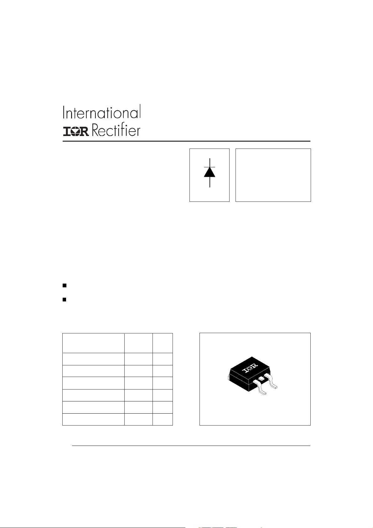
Package Outline
2
Pak (SMD-220)
D
1
10ETF..S QUIETIR Series
I2140 rev. A 12/99
Voltage Ratings
V
, maximum V
RRM
Part Number
peak reverse voltage peak reverse voltage 150°C
VVmA
10ETF02S 200 300 2
10ETF04S 400 500
10ETF06S 600 700
Absolute Maximum Ratings
Parameters 10ETF..S Units Conditions
I
Max. Average Forward Current 10 A @ TC = 128° C, 180° conduction half sine wave
F(AV)
I
Max. Peak One Cycle Non-Repetitive 150 10ms Sine pulse, rated V
FSM
Surge Current 160 10ms Sine pulse, no voltage reapplied
I2t Max. I2t for fusing 112.5 10ms Sine pulse, rated V
160 10ms Sine pulse, no voltage reapplied
2
√t Max. I2√t for fusing 1125 A2√s t = 0.1 to 10ms, no voltage reapplied
I
A
A2s
, maximum non repetitive I
RSM
RRM
RRM
applied
applied
RRM
Electrical Specifications
Parameters 10ETF..S Units Conditions
VFMMax. Forward Voltage Drop 1.2 V @ 10A, TJ = 25°C
rtForward slope resistance 12.7 mΩ TJ = 150°C
V
Threshold voltage 1.25 V
F(TO)
IRMMax. Reverse Leakage Current 0.1 TJ = 25 °C
2.0 TJ = 150 °C
mA
Recovery Characteristics
Parameters 10ETF..S Units
trrReverse Recovery Time 145 ns IF @ 10Apk
IrrReverse Recovery Current 2.75 A @ 25A/ µs
QrrReverse Recovery Charge 0.32 µC @ 25°C
S Snap Factor 0.6
2
Conditions
VR = rated V
RRM
www.irf.com
10ETF..S QUIETIR Series
Thermal-Mechanical Specifications
Parameters 10ETF..S Units Conditions
TJMax. Junction Temperature Range - 40 to 150 °C
T
Max. Storage Temperature Range - 40 to 150 °C
stg
R
Max. Thermal Resistance Junction 1.5 °C/W DC operation
thJC
to Case
R
Max. Thermal Resistance Junction 40 °C/W
thJA
to Ambient (PCB Mount)**
TsSoldering Temperature 240 °C
wt Approximate Weight 2 (0.07) g (oz.)
Case Style D2Pak (SMD-220)
**When mounted on 1" square (650mm2) PCB of FR-4 or G-10 material 4 oz (140µm) copper 40°C/W
For recommended footprint and soldering techniques refer to application note #AN-994
I2140 rev. A 12/99
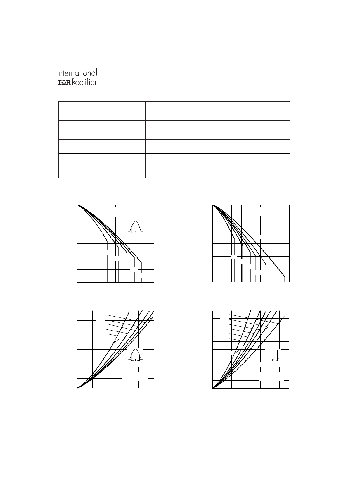
150
145
140
135
130
125
120
Maxim um Allowable Case Temperature (°C)
024681012
Average Forward Current (A)
1 0 ET F..S S e ri e s
R (D C ) = 1.5 °C /W
thJC
Condu ction Angle
30°
60°
90°
120°
180°
Fig. 1 - Current Rating Characteristics
16
14
12
10
8
6
4
2
0
Maxim um Average Forward P ower Loss (W)
0246 810
180°
120°
90°
60°
30°
RMS Limit
Conduction Angle
1 0E TF . .S S er ie s
T = 150° C
J
A ve ra g e Fo rw a rd C urre nt (A )
150
145
140
135
130
125
120
M aximum Allowable Case Temperature (° C)
0246810121416
Average Fo rwa rd C urre nt (A)
10ETF..S Series
R (DC ) = 1.5 °C/W
thJC
Condu ction Period
30°
60°
90°
120°
180°
Fig. 2 - Current Rating Characteristics
20
DC
180°
120°
16
90°
60°
30°
12
RM S Lim it
8
Conduction Period
4
0
Maxim um Average Forward Power Loss (W)
0481216
A ve ra g e Fo rw a rd C urre nt (A )
1 0ETF..S Series
T = 150° C
J
Fig. 3 - Forward Power Loss Characteristics Fig. 4 - Forward Power Loss Characteristics
DC
www.irf.com
3

10ETF..S QUIETIR Series
I2140 rev. A 12/99
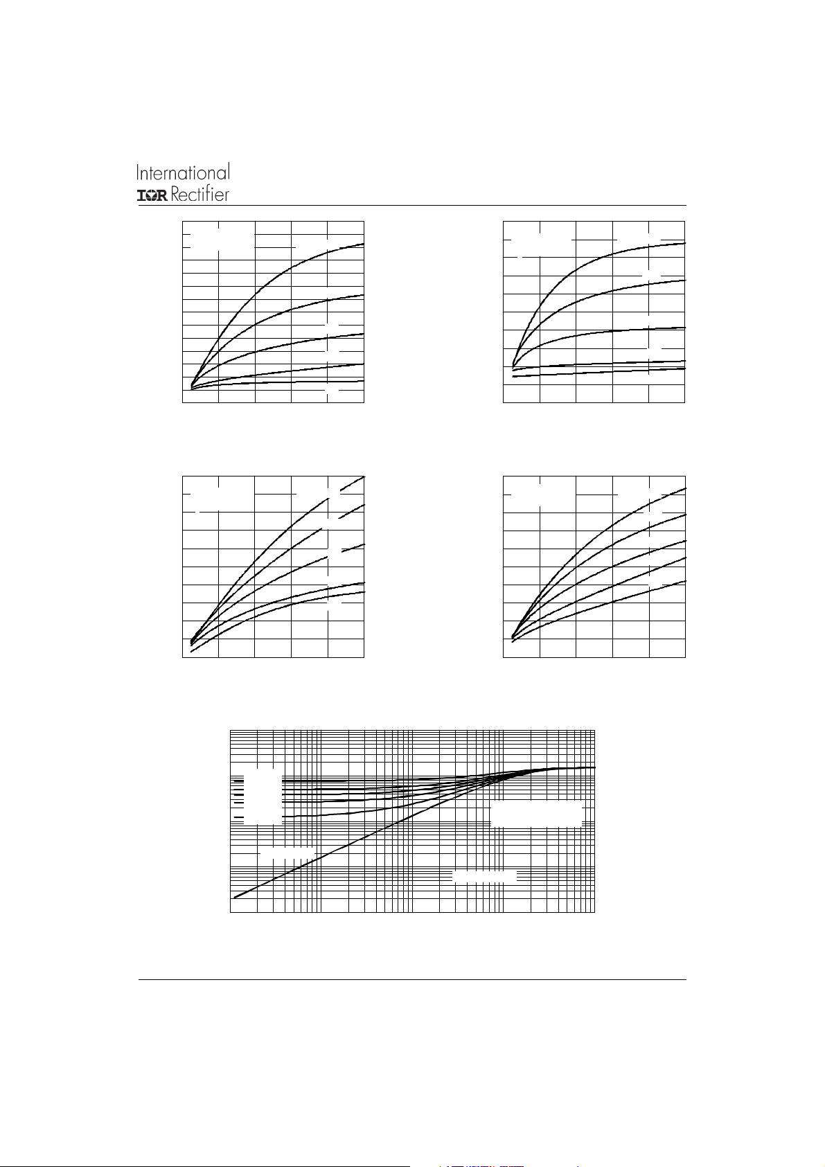
160
At Any Rated Load Condition And With
Rated V App lied Following Surg e.
140
120
100
80
60
Peak Half Sine Wave Forward Current (A)
40
1 10 100
Numb er Of Equa l Am plitude Half Cy cle Current Pulses (N)
Fig. 5 - Maximum Non-Repetitive Surge Current
RRM
10ETF..S Se ries
Initial T = 1 50° C
J
@ 60 Hz 0.0083 s
@ 50 Hz 0.0100 s
100
180
M axim um N o n Re petitive Su rge C urrent
160
140
120
100
80
60
Peak Half Sine Wave Forward Current (A)
40
0.01 0.1 1
Versu s Pu lse Tra in D uration.
N o V olta ge Re ap plie d
Rated V R ea p plied
10ETF..S Se ries
Pulse Train Duration (s)
Initial T = 1 50 ° C
J
RRM
Fig. 6 - Maximum Non-Repetitive Surge Current
10
Instantaneous Forward Current (A)
1
0.511.522.53
Instant an eou s Forw ard Volt age (V)
T = 25°C
J
T = 150°C
J
10ETF..S Series
Fig. 7 - Forward Voltage Drop Characteristics
0.2
0.15
0.1
0.05
10ETF..S Serie s
T = 25 °C
M a xim u m Re v erse Re c ov e ry T im e - Trr (µs)
J
0
0 40 80 120 160 200
Ra te O f Fall O f Forw ard C urren t - di/dt (A/µ s)
I = 20 A
FM
10 A
5 A
2 A
1 A
0.4
0.3
I = 20 A
0.2
0.1
10ETF..S Se ries
T = 150 °C
Max im um Reverse Recovery Time - Trr (µs)
J
0
0 4 0 80 120 160 200
Rate Of Fall Of Fo rward Current - di/dt (A/µs)
FM
10 A
5 A
2 A
1 A
Fig. 8 - Recovery Time Characteristics, TJ = 25°C Fig. 9 - Recovery Time Characteristics, TJ = 150°C
4
www.irf.com
1.4
10ETF..S Series
T = 25 °C
1.2
J
I = 20 A
FM
1
0.8
0.6
0.4
10 A
5 A
2 A
0.2
1 A
0
0 40 80 120 16 0 200
M a xim u m Re ver se Re co v ery C h a rge - Q rr (µC )
Rate Of Fall Of Forward Current - di/dt (A/µs)
Fig. 10 - Recovery Charge Characteristics, T
15
10ETF..S Series
T = 25 °C
J
12
9
6
3
I = 20 A
FM
10 A
1 A
10ETF..S QUIETIR Series
I2140 rev. A 12/99
2.5
10ETF..S Series
T = 150 ° C
J
2
1.5
1
0.5
0
0 40 80 120 16 0 200
M a xim u m R eve rse R e co v ery C h a rg e - Q rr (µC )
Rate Of Fall Of Forward Current - di/dt (A/µs)
= 25°C Fig. 11 - Recovery Charge Characteristics, TJ = 150°C
J
20
10ETF..S Series
T = 150 °C
J
16
5 A
2 A
12
8
4
I = 20 A
FM
10 A
5 A
2 A
1 A
I = 20 A
FM
10 A
5 A
2 A
1 A
0
M axim um Rev e rse Reco ver y C urrent - Irr (A)
0 40 80 120 160 200
Ra te O f Fall Of Forward Current - di/dt (A/µs)
Fig. 12 - Recovery Current Characteristics, T
10
thJC
D = 0.33
D = 0.50
1
D = 0.25
D = 0.17
D = 0.08
0.1
Single Pulse
0.01
0.001
Transient Thermal Impedance Z (°C/W)
0.001 0.01 0.1 1 10
Fig. 14 - Thermal Impedance Z
www.irf.com
= 25°C
J
Fig. 13 - Recovery Current Characteristics, T
10ETF..S Series
Square Wa ve Pulse D uration (s)
Characteristics
thJC
0
Maxim um Reverse Recovery Curre nt - Ir r (A)
0 40 80 120 160 200
Ra te Of Fall Of Forw a rd Curren t - di/dt (A/µs)
Steady State Value
(DC O peration )
= 150°C
J
5

10ETF..S QUIETIR Series
I2140 rev. A 12/99
Ordering Information Table
Device Code
10 E T F 06 S TRL
1 - Current Rating
2 - Circuit Configuration: E = Single Diode
3 - Package: T = TO-220AC
4 - Type of Silicon: F = Fast Soft Recovery Rectifier
5 - Voltage code: Code x 100 = V
6 - S = TO-220 D2Pak (SMD-220) Version
7 - Tape and Reel Option
Outline Table
15.49 (0 .61)
14.73 (0 .58)
1.40 (0.055)
3X
1.14 (0.045)
1
3
TRL = Left Reel
TRR = Right Orientation Reel
10.16 (0.40)
REF.
93°
2.61 (0 .10)
2.32 (0 .09)
8.89 (0.35)
REF .
0.93 (0.37)
2X
0.69 (0 .27)
524
RRM
6.47 (0 .25)
6.18 (0 .24)
6 7
02 = 200V
04 = 400V
08 = 800V
4.69 (0.18)
4.20 (0 .16)
1.32 (0 .05)
1.22 (0 .05)
5.28 (0.21)
4.78 (0.19)
0.55 (0.02)
0.46 (0.02)
MINIMUM RECOMMENDED FOOTPRINT
11.43 (0 .45)
13
2
Dimensions in millimeters and inches
6
4.57 (0 .18)
4.32 (0 .17)
0.61 (0.02) MAX.
5.08 (0.20) REF .
8.89 (0.35)
3.81 (0 .15)
2.08 (0.08)
2X
17.78 (0.70)
2.54 (0 .10)
2X
www.irf.com

Marking Information
10ETF..S QUIETIR Series
I2140 rev. A 12/99
EXAMPLE: THIS IS AN 10ETF06S
BASE
+
(K)
2
(A)
1
(A)
3
--
Tape & Reel Information
TRR
FEED DIRECTION
TRL
1.85 (0.073)
1.65 (0.065)
4.10 (0.161)
3.90 (0.153)
10.90 (0.429)
10.70 (0.421)
INTERNATIONAL
RECTIFIER LOGO
ASSEMBLY
LOT CODE
1.60 (0.063)
1.50 (0.059)
16.10 (0.634)
15.90 (0.626)
9G3A
1.60 (0.063)
1.50 (0.059)
1 1 .6 0 (0 .45 7 )
1 1 .4 0 (0 .44 9 )
1.75 (0.069)
1.25 (0.049)
(K)
10ETF06S
9512
DIA.
15.42 (0.609)
15.22 (0.601)
DIA .
PART NUMBER
DATE CODE (YYWW)
YY = YEAR
(A)(A)
WW = WEEK
0.3 68 (0.0145)
0.3 42 (0.0135)
2 4 .3 0 (0 .95 7 )
2 3 .9 0 (0 .94 1 )
4.72 (0.186)
4.52 (0.178)
FEED DIRECTION
360 (14.173)
DIA. M AX.
www.irf.com
13.50 (0.532)
12.80 (0.504)
DIA .
Dimensions in millimeters and inches
26.40 (1.039)
24.40 (0.961)
6 0 (2 .3 6 2)
DIA . MIN.
SMD-220 Tape & Reel
Wh en ordering, indicate th e part
num ber, part orientation, and the
quantity. Quantities are in multiples
of 800 p ieces p er reel for both
TRL and T RR .
7
10ETF..S QUIETIR Series
I2140 rev. A 12/99
WORLD HEADQUARTERS: 233 Kansas St., El Segundo, California 90245 U.S.A. Tel: (310) 322 3331. Fax: (310) 322 3332.
EUROPEAN HEADQUARTERS: Hurst Green, Oxted, Surrey RH8 9BB, U.K. Tel: ++ 44 1883 732020. Fax: ++ 44 1883 733408.
IR SOUTHEAST ASIA: 1 Kim Seng Promenade, Great World City West Tower,13-11, Singapore 237994. Tel: ++ 65 838 4630.
http://www.irf.com Fax-On-Demand: +44 1883 733420 Data and specifications subject to change without notice.
8
IR CANADA: 15 Lincoln Court, Brampton, Markham, Ontario L6T3Z2. Tel: (905) 453 2200. Fax: (905) 475 8801.
IR GERMANY: Saalburgstrasse 157, 61350 Bad Homburg. Tel: ++ 49 6172 96590. Fax: ++ 49 6172 965933.
IR ITALY: Via Liguria 49, 10071 Borgaro, Torino. Tel: ++ 39 11 4510111. Fax: ++ 39 11 4510220.
IR FAR EAST: K&H Bldg., 2F, 30-4 Nishi-Ikebukuro 3-Chome, Toshima-Ku, Tokyo, Japan 171. Tel: 81 3 3983 0086.
IR TAIWAN: 16 Fl. Suite D.207, Sec. 2, Tun Haw South Road, Taipei, 10673, Taiwan. Tel: 886 2 2377 9936.
www.irf.com
 Loading...