

Page 1
Analog Weight Transmitter
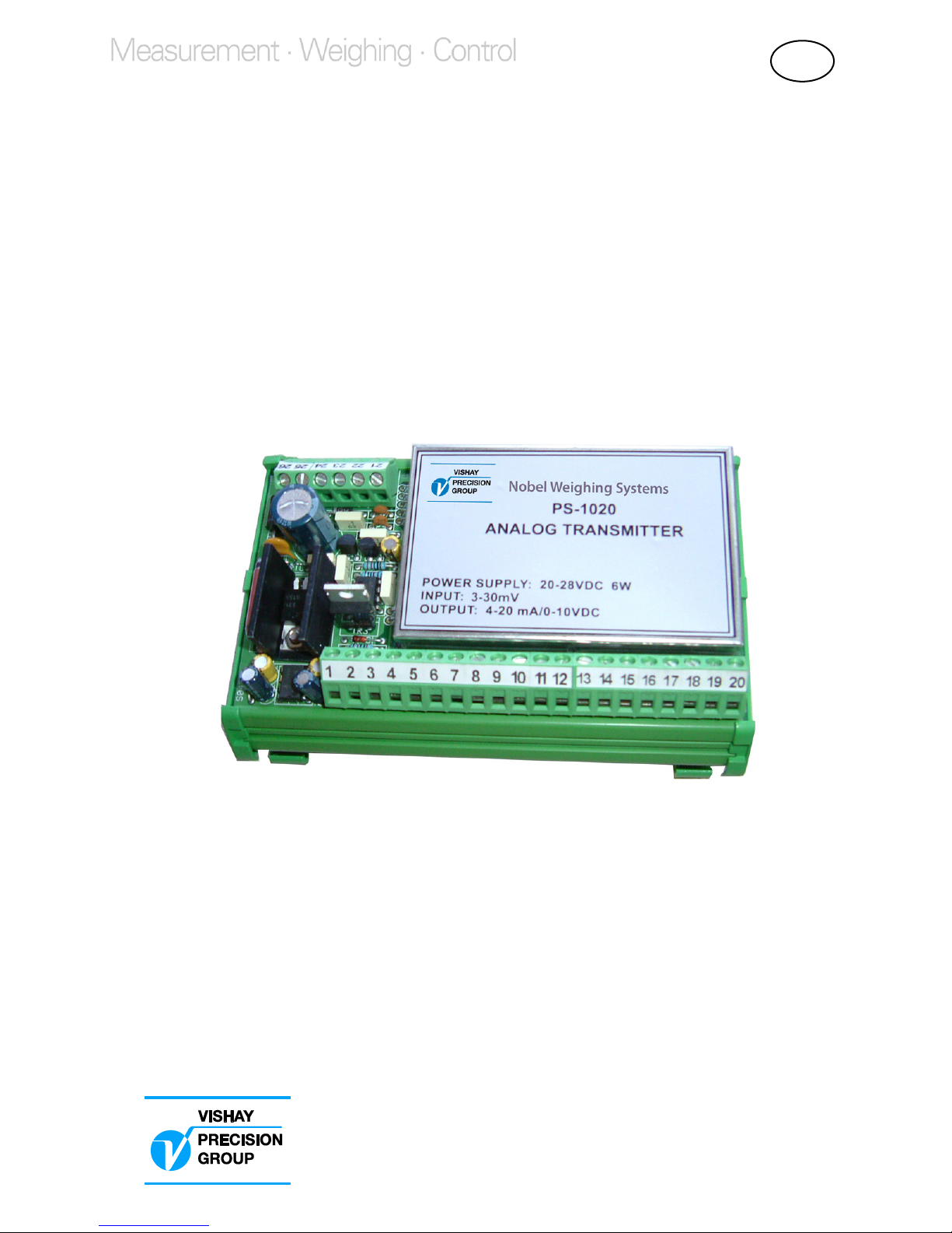
PS-1020
Installation and Operating Manual
GB
Page 2

Page 3

LIST OF CONTENTS
Section 1, General information
Introduction .............................................................. 3
Description ............................................................... 3
Specifications .......................................................... 4
Wiring connections .................................................. 5
Section 2, Calibration
Calculations ............................................................. 7
Calibration Procedure .............................................. 8
Section 3, Options
24 V Power Supply, PS-121 ................................... 11
Appendices
EC DECLARATION OF CONFORMITY
for Analog Weight Transmitter PS-1020 ... Appendix 1
EC DECLARATION OF CONFORMITY
for 24 V Power Supply PS-121 ................. Appendix 2
2
Page 4

Page 5

Introduction
PS-1020 Analog Transmitters are electronic devices utilizing
solid-state integrated components. They provide the user with
a selectable voltage or current output directly proportional to
the input signal within a specified linearity.
Description
The transmitters are intended for field mounting close to the
vessel site, thereby reducing installation costs. An integral
20-connector terminal strip provides connections for up to
four transducers, thus eliminating the need for a separate
summing junction box.
Two screw type terminal strips provide connections for the
supply voltage, transducer wiring, and analog outputs.
The zero and span adjustments for the analog outputs are
accomplished with two sets of dip-switches and trim pots.
The units also include an adjustable filter which can be used to
stabilize the output. Filtering is used to minimize the effects of
vibration caused by agitators or other devices.
The standard packaging is an ABS plastic DIN-Rail mounted
enclosure.
The transmitters are available with an optional 24 Vdc power
supply enabling the unit to be operated with 115 Vac.
For additional information, please refer to Section 3.
SECTION 1
GENERAL INFORMATION
3
Page 6

Specifications
PERFORMANCE
Full Scale Range 3 mV to 30 mV
Linearity ±0.2% of full scale
Excitation Voltage 10 Vdc
Load Current 200 mA (four - 350 ohm load cells)
Thermal Stability 28 ppm/°F (full scale range)
ENVIRONMENTAL
Operating Temperature -10 to +40°C
Storage Temperature -20 to +50°C
Relative Humidity 85% non-condensing
ELECTRICAL
Input Voltage 24 Vdc ±15%
Power Consumption 6 watts max
ANALOG OUTPUT (jumper selectable)
Voltage 0 to 10 Vdc
(2kohm min load)
Current 0 to 20 or 4 to 20 mA
(500 ohm max load)
CONFIGURATION
Coarse Zero 4-position DIP-switch
Fine Zero 20-turn trim pot
Coarse Span 4-position DIP-switch
Fine Span 20-turn trim pot
Analog Filter adjustable, 270° turn trim pot
ENCLOSURE
Overall Dimensions 134 x 93 x 60 mm (L x H x D)
Mounting DIN rail mount
Material ABS Plastic
Weight 215 gram
Wiring Connections terminal blocks, pitch 5 mm
OPTIONS
230 VAC Power Supply DIN rail mount
Vishay BLH is continually seeking to improve
product quality and performance.
Specifications may change accordingly.
4
Page 7

FIGURE 1
Wiring Connections
Mount the transmitter horizontally on a section of DIN-Rail with Terminal Block TB1 positioned on the bottom. If an
optional 230 Vac to 24 Vdc power supply is used, the cable between the two devices must not exceed 1 meter.
TB2
26 25 24 23 22 21
TB1
1 2 3 4 5 6 7 8 9 10 11 12 13 14 15 16 17 18
19
20
5
Page 8

TB2
1. - Excitation (cell # 1) 11. - Excitation (cell # 3) 21. + 0/20 or + 4/20 mA
2. + Excitation (cell # 1) 12. + Excitation (cell # 3) 22. + 0-10 Vdc
3. - Signal (cell # 1) 13. - Signal (cell # 3) 23. - Analog Output
4. + Signal (cell # 1) 14. + Signal (cell # 3) 24. - 24 Vdc (supply)
5. Shield 15. Shield 25. + 24 Vdc (supply)
6. - Excitation (cell # 2) 16. - Excitation (cell # 4) 26. Ground
7. + Excitation (cell # 2) 17. + Excitation (cell # 4)
8. - Signal (cell # 2) 18. - Signal (cell # 4)
9. + Signal (cell # 2) 19. + Signal (cell # 4)
10. Shield 20. Shield
TB1
The PS-1020 is designed to be installed in the field close to the vessel. Terminal strip TB1 provides connections
for up to four transducers, thereby eliminating the need for a separate summing junction box.
NOTE: Some transducer manufacturers utilize a 6-conductor cable (+/- Sense leads). When using these type of
transducers, the + Sense lead must be connected to the + Excitation terminal and the - Sense lead must be
connected to the - Excitation terminal.
6
Page 9

Prior to calibrating the instrument perform the following calculations.
This will enable you to determine where the dip-switches should be
positioned for zero and span. Obtain the capacity and full scale
output of the transducer/s from the calibration certificates.
If required, convert them into the engineering units being used in
the system.
Use the above values in the following formulas to determine
the zero and span mV values.
Multiply the full scale mV/V output of the transducer/s by
the excitation voltage to obtain mV.
Example: 3.0 mV/V x 10 Vdc = 30 mV.
Zero (mV) = Z x O / C
Z = Tare weight (vessel, agitator, etc)
O = Full scale output in mV
C = Total capacity of the transducers.
Set the zero adjustment dip-switches so the calculated value is
within the minimum/maximum mV ranges given in Table 1 (page 9).
Span (mV) = S x O / C
S = Net weight (live or product weight)
O = Full scale output in mV
C = Total capacity of the transducers.
Set the span dip-switches so the calculated value is within the
minimum and maximum mV ranges given in Table 2 (page 10).
Sample calculation:
Three 1000 kg load cells, output = 3.0 mV/V
Tare weight = 500 kg.
Net weight = 2000 kg.
3.0 mV/V x 10 Vdc = 30 mV
Zero (mV) 500 kg x 30 mV / 3,000 kg = 5 mV
Table 1 dip-switch setting = Off, On, Off, Off (3.0 to 5.5 mV)
Span (mV) 2000 kg x 30 mV / 3,000 kg = 20 mV
Table 2 dip-switch setting = On, On, On, On (15.2 to 24.7 mV)
SECTION 2
CALIBRATION
7
Page 10

Calibration Procedure
Remove the metal cover to expose the dip-switches, jumpers
and trim pots as shown in Figure 2 below.
Set the zero and span dip-switches so the calculated values are
within the minimum and maximum mV ranges given in Tables 1
and 2.
Position jumper J1 for current or voltage output. See Figure 2.
Connect a digital multi-meter to terminal strip TB2
terminals 21 and 23 for current output or to
terminals 22 and 23 for voltage output.
Apply power to the unit and allow a couple of minutes for
the transmitter to warm up before making any adjustments.
Remove any weight from the system and adjust the fine zero
trim pot for a reading 0 Vdc or 4 mA. Turn the trim pot
clockwise to increase the output, or counter-clockwise to
decrease the output.
TB2
TB1
1
2
3
4
1
2
3
4
ZERO ADJ. SPAN ADJ.
FIGURE 2
Zero & Span Adjustments
J1
J1 installed = 4/20 mA
J1 removed = 0-10 Vdc
8
Page 11

1 2 3 4 mV
min
mV
max
OFF OFF OFF OFF -0.8 1.6
ON OFF OFF OFF 1.2 3.7
OFF ON OFF OFF 3.0 5.5
ON ON OFF OFF 4.6 7.1
OFF OFF ON OFF 5.9 8.4
ON OFF ON OFF 7.2 9.7
OFF ON ON OFF 8.3 10.8
ON ON ON OFF 9.3 11.8
OFF OFF OFF ON 10.2 12.8
ON OFF OFF ON 11.0 13.6
OFF ON OFF ON 11.8 14.3
ON ON OFF ON 12.5 15.0
OFF OFF ON ON 13.1 15.7
ON OFF ON ON 13.7 16.2
OFF ON ON ON 14.3 16.8
ON ON ON ON 14.8 17.3
TABLE 1
Calibration Procedure (cont’d)
Apply a known weight and adjust the fine span trim pot for
the correct output. Turning the trim pot clockwise
increases the output while turning it counter clockwise
decreases the output.
Re-check “zero” and “span” calibration and re-adjust if required.
Replace the metal cover after calibration has been completed.
Analog Filter Adjustment
If the output is unstable under normal operating conditions,
slowly turn the filter adjustment clockwise until the output
stabilizes.
See Figure 3 (page 10) for location of the filter adjustment.
9
Page 12

1 2 3 4 mV
min
mV
max
OFF OFF OFF OFF 2.6 2.8
ON OFF OFF OFF 2.8 3.0
OFF ON OFF OFF 3.0 3.2
ON ON OFF OFF 3.2 3.5
OFF OFF ON OFF 3.4 3.7
ON OFF ON OFF 3.7 4.0
OFF ON ON OFF 4.0 4.4
ON ON ON OFF 4.3 4.9
OFF OFF OFF ON 4.8 5.4
ON OFF OFF ON 5.3 6.1
OFF ON OFF ON 5.9 7.0
ON ON OFF ON 6.8 8.2
OFF OFF ON ON 7.8 9.7
ON OFF ON ON 9.3 12.2
OFF ON ON ON 11.6 16.5
ON ON ON ON 15.2 24.7
TABLE 2
Span Adjustment Dip-switches
FIGURE 3
Analog Filter Adjustment
TB2
TB1
J2
J2 removed = No Filtering
J2 installed = Filter Activated
Filter
Adjustment
10
Page 13

SECTION 3
OPTIONS
Specifications
Power
Input Voltage
Output Voltage
Power Consumption
Fuse
Isolation
Environmental
Operating Temp. Range
Storage Temp. Range
Relative Humidity
Enclosure
Dimensions (L x H x D)
Mounting
Material
Weight
230 Vac, 50/60 Hz
24 Vdc (nominal)
10 VA maximum
T 160 mA
Class II
-10 to +40ºC
-20 to +50°C
85% non-condensing
50 x 90 x 60 mm
35 mm DIN-Rail
ABS Plastic
360 g
24 V Power Supply, PS-121
Installation
• Make sure the installation complies with local regulations
and electrical codes.
• Connect AC voltage to the terminals marked “L” and “N”.
• The DC voltage is available on the terminals
marked “+” and “-”.
• A red LED is illuminated when the power supply is “ON”.
Refer to Figure 4 on the following page for terminal locations.
11
Page 14

Fuse Replacement
• The following procedures require work inside the power
supply enclosure and should be performed by qualified
Vishay service personnel.
• Before opening the unit, disconnect the AC voltage.
• Remove the front cover from the power supply.
• Press down gently on the cover of the fuse holder, and
turn counter-clockwise.
• Pull out the cover and fuse as an assembly, replace fuse
with a new one.
• Re-install fuse and cover as an assembly, press down
gently and turn clockwise.
• Replace the front cover on the power supply.
• Re-apply AC voltage to the unit.
In the event of a malfunction, please contact the nearest Vishay
service office for assistance. Any attempt to modify or repair
the power supply will void the manufacturers warranty.
FIGURE 4
PS-121 Power Supply
L N + -
230 Vac 24 Vdc
Fuse
LED
12
Page 15

13
APPENDIX 1
Page 16

14
Page 17

15
APPENDIX 2
Page 18

Page 19

Page 20

Vishay Nobel AB
Box 423, SE-691 27 Karlskoga, Sweden
Phone +46 586 63000 · Fax +46 586 63099
pw.se@vishaypg.com
www.weighingsolutions.com
Document no. 35202
Article no. 600 690 R2
© Vishay Nobel AB, 2011-06-22
Subject to changes without notice.
 Loading...