

Page 1
查询PRV61WLHR供应商
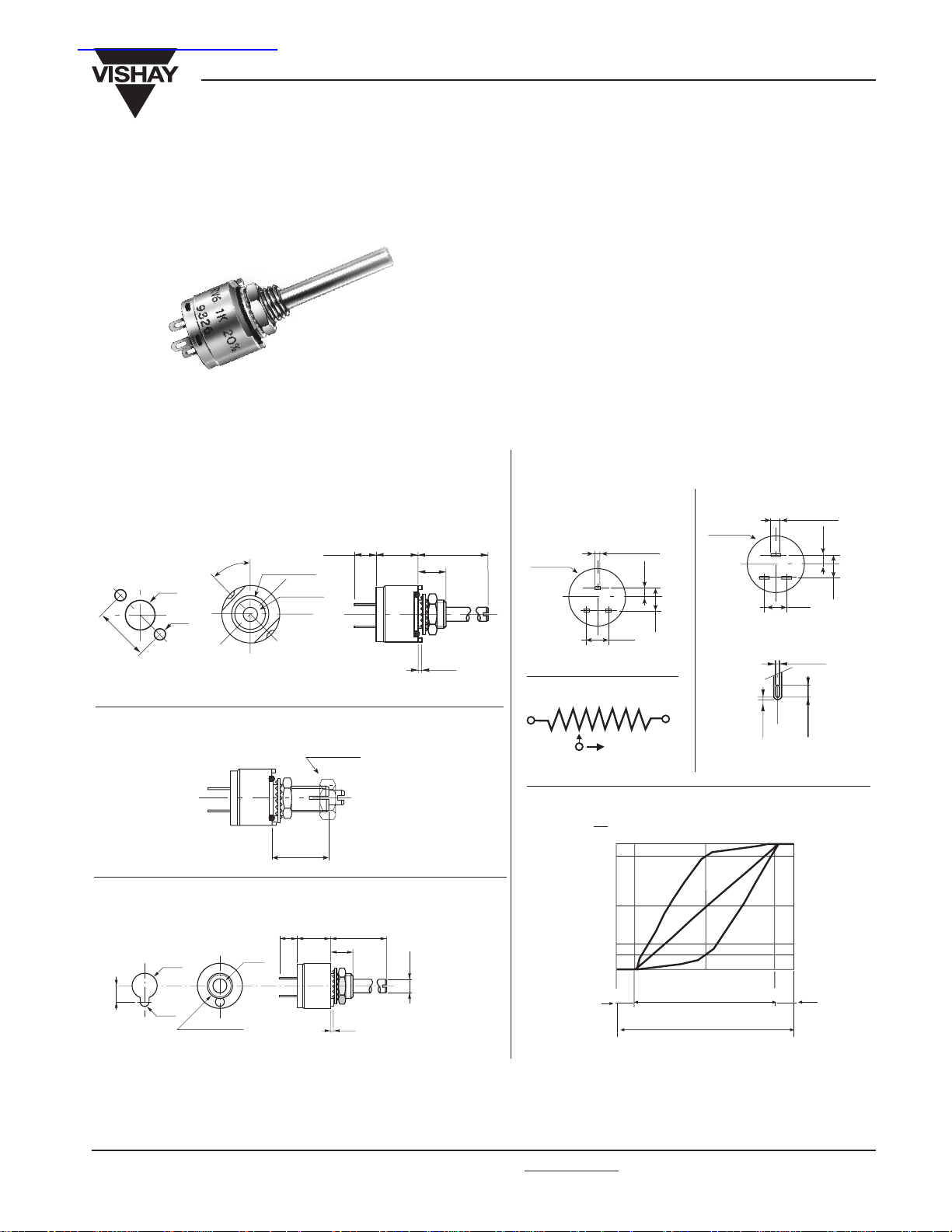
Fully Sealed Potentiometers Cermet (PRV6)
PRV6, PARV6
Vishay Sfernice
Conductive Plastic (PARV6)
DIMENSIONS in millimeters [inches]
PRV cermet PRV6
PARV conductive plastic PARV6
Shafts and bushings : 6 - 61 - 62
6LC - 61LC - 62LC
Panel cutout
A
Ø 6.5
(0.256”)
12.4
(0.490”)
Ø 2.5
(0.098”)
Locking shaft H option :
61H - 62H
61LCH - 62LCH
Ø 6.35 (1.4”)
32 Threads/inch
Ø 3.17 (1/8”)
5
(0.200”)
Conic nut
wrench 8 (3/16”)
CL
B
0.8
(0.031”)
FEATURES
• PRV6 1.5 Watt at 70°C
• PARV6 0.75 Watt at 70°C
• CECC 41300
• Military performances
• Low cost
• Fully sealed and panel sealed
• Compatible RV6 (MIL R 94)
• High power rating (cermet)
• High stability
• Mechanical life 50,000 cycles
Terminal options available
PCB pins
W option
Ø 12.7 (1/2”)
(0.031” x 0.12”)
2
3
CIRCUIT DIAGRAM
a
(1) (3)
b
CW
(2)
0.8 x 0.3
1
5.08
(0.200”)
on all types
2
(0.79”)
5.08
(0.200”)
c
Solder lugs
Ø 12.7 (1/2”)
(0.063 x 0.012”)
2
3
0.5
(0.020”)
1.6 x 0.3
2
1
5.08
(0.200”)
0.8 (0.031”)
2.4
(0.094”)
(0.079”)
5.08
(0.200”)
B
Shaft Dia 4 mm : 6Q - 61Q - 61QH
6QLC - 61QLC - 61QLCH
Ø 7.2
4.3
Ø 2.6
Ø D = M7 x 0.75
See ordering information for quotation
Ø d = 4
Document Number: 51035
Revision 15-Apr-02
5
L
C
B
0.8
For technical questions, contact sfer@vishay.com
VARIATION LAWS
Vs
%
Ve
90%
50%
20%
Ø 4
10%
15° 15°
F
A
L
25° 50° 75°
Electrical travel 270°
Mechanical travel 300°
TAPERS
Tapers A - L - F - are measured between the wiper (2)
and the ccw terminal (1).
www.vishay.com
93
Page 2
PRV6, PARV6
Vishay Sfernice
Fully Sealed Potentiometers Cermet (PRV6)
Conductive Plastic (PARV6)
ELECTRICAL SPECIFICATIONS
PRV6 PARV 6
Resistive Element
Electrical Travel 270° ±15° 270° ± 15°
Resistance Range
Linear Law (A)... 20Ω to 10MΩ 1 kΩ to 1MΩ
Non Linear Laws (F-L) 470Ω to 1MΩ 470Ω to 500 kΩ (± 20%)
Tolerance Standard ± 20% ± 10% ± 20 %
On Request ± 5 % ± 10 % (1 kΩ to100 kΩ)
Power Rating at + 70°C Linear 1.5 W 0.75W
Others Tapers 0.75 W 0.4W
mperature Coeffi cient
Te
Li
miting Element Voltage 350 V 350 V
Contact Resist. Variation CRV 2% or 3Ω
End Resistance (Typical) 1Ω
Dielectric Strength 1750 VRMS (2000 VRMS on request)
Insulation Resistance (500VDC) 10
± 100ppm/°C ± 1000ppm/°C
MECHANICAL SPECIFICATIONS
Mechanical Travel 300° ± 5°
Operating Torque 0.5 to 2 Ncm
or... 0.7 to 3 oz.in.
End Stop Torque max 35 Ncm
or... 3 lb.in.
Tightening Torque max
150 Ncm
or... 13 lb.in
ENVIRONMENTAL SPECIFICATIONS
PRV6 PARV6
Temperature Range –
Climatic Category 55/125/56 40/125/56
Sealing fully sealed container
IP67 and panel sealed
55°C + 125°C – 40°C + 125°C
cermet conductive plastic
6
MΩ
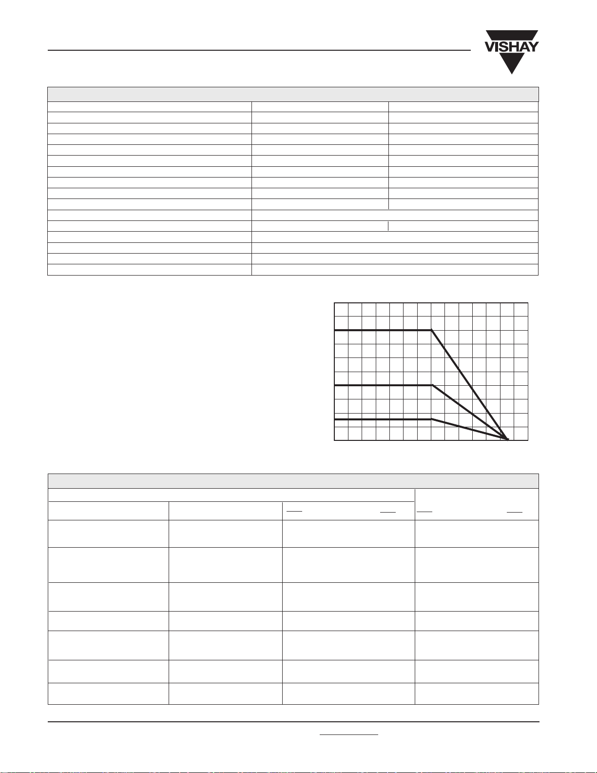
POWER RATING CHART
PRV6 linear law
1.50
PARV6 linear laws/
PRV6 non linear law
0.75
RATED POWER IN WATTS
PARV6 non linear law
0.4
0
0 20 40 60 70 80 100 125
AMBIENT TEMPERATURE IN DEGREES CELCIUS
PERFORMANCE (PRV6)
Load Life
Climatic Sequence
Long Term Damp Heat
Rapid Temperature Change
Vibration
Shock
Rotational Life
www.vishay.com
94
CECC 41 300 and/or MIL R 94
CONDITIONSTESTS
1000 h at rated power
90'/30' - temperature 70°C
Phase A dry heat 100°C
Phase B damp heat
Phase C cold –55°C
Phase D damp heat 5 cycles
56 days
5 cycles – 55°C at + 125°C
10g 55 to 2000 Hz
2 h each direction
100 g 6 ms 20 shocks
50.000 cycles
For technical questions, contact sfer@vishay.com
TYPICAL VALUES AND DRIFTS
∆RT ∆R1-2
RT
± 10%
CRV < 7% Rn
± 10% ± 10%
± 10% ± 10%
Insulation resist. > 100MΩ
± 3%
± 2% no CUT > 0.1 ms ± 5%
± 2% ± 5%
± 10% CRV < 7 % Rn ± 3% CRV < 2% Rn
REQUIREMENTS
(%)
R1-2
∆RT ∆R1-2
(%)
(%)
RT
R1-2
± 1%
CRV < 3% Rn
± 0.5% ± 1%
± 0.5% ± 1%
Insulation resist. > 10
± 0.5%
± 0.1% ± 0.2 %
± 0.1% ± 0.2 %
Document Number: 51035
Revision 15-Apr-02
4
MΩ
(%)
Page 3

PRV6, PARV6
Fully Sealed Potentiometers Cermet (PRV6)
Conductive Plastic (PARV6)
STANDARD RESISTANCE ELEMENT DATA
STANDARD
RESISTANCE
VALUES
100
200
500
10k
20k
50k
100k
200K
500K
10M
PRV6 LINEAR LAW
MAX.
POWER
AT 70°C
Ω
20
W
1.5
50
1k
2k
5k
1.5
1.22
0.61
0.25
0.12
1M
0.06
2M
0.025
5M
0.012
MAX.
WORKING
VOLTAGE
V
5.48
8.66
12.2
17.3
27.4
38.7
54.8
86.6
122.5
173
274
350
350
350
350
350
350
350
MAX. CUR.
THROUGH
ELEMENT
PACKAGING
Carton box of 50, code: BO50
ORDERING INFORMATION
PRV6 NON LINEAR LAWS
MAX.
POWER
AT 70°C
W
274
173
122
87
55
0.75
38.7
27.4
17.3
12.2
8.26
5.65
0.75
3.5
0.61
1.75
0.25
0.7
0.35
0.17
0.07
0.035
MAX.
WORKING
VOLTAGE
VmA mA
27.3
38.2
61.2
87
122
194
273
350
350
MAX. CUR.
THROUGH
ELEMENT
27.4
19.3
12.2
8.7
6.1
3.9
2.74
1.75
0.7
T.C.
– 55°C
+ 125°C
ppm/°C
0
+ 200
PRV6
± 100
Vishay Sfernice
PANEL SEALING
Except for dia. 4 mm shaft, an O.ring is supplied
potentiometer. This O.ring should be placed into the groove
of the body and ensures the panel sealing.
For dia. 4mm shaft please see note “P” in ordering information.
SHAFTS
Shaft lengths are measured from the mounting face to the
free end of the shaft. Special shafts are available if the
customer supplies a drawing. The shaft slot is aligned to
the wiper within ± 10°.
HARDWARE
Nuts, washer and O.ring are separately supplied (not
mounted on the potentiometer), in a small bag placed in
the packaging.
LOCATING PEG
Except for dia. 4 mm shaft, the potentiometers are delivered
with 2 opposite
locating pegs orientated at 45°. These
2 pegs can be easily broken-off by the customer.
On request, the orientation of the pegs can be at 30° instead
of 45°. Order Designation : PRV6 L (see ordering information).
MARKING
VISHAY trademark, series, style, ohmic value (in Ω, kΩ
or MΩ), tolerance in %, taper code, manufacturing date (4
digits : 2 for year, 2 for week), terminal 1.
with the
PRV cermet
PARV conductive
plastic
SERIE
Standard C = 9.5
no code
Option C = 12.1
code S
BODY LENGTH
BUSHING
Length
B
6.35
9.5
12.5
6.5
9.5
6.35
9.5
12.5
6.5
9.5
6.5
9.5
6.5
9.5
SHAFT
Dia
d
3 or 3.17
3 or 3.17
3 or 3.17
4
4
3 or 3.17
3 or 3.17
3 or 3.17
4
4
4
4
4
4
Dia
D
6,35
6
6,35
61
6,35
62
7
6Q
7
61Q
6,35
6LC
6,35
61LC
6,35
62LC
7
6QLC
61QLC
6QPLC
61QPLC
LC = Low Current
Shaft dia 3.17 and 3 are standard
panel sealed
Shaft dia 4 : please note “P” for
panel sealed option
7
7
6QP
7
61QP
7
7
SHAFTS and BUSHINGS
Solder Lugs
no code
PCB pins
code W
TERMINALS
A : standard 45°
no code
A : option 30°
code L
not available
for 6Q and 61Q
versions
See drawing
LOCATING PEGS
Code H
not available
for 6-6Q
versions
LOCKING SHAFT
From mounting face
Dia
d
3.17
3.17
3.17
3.17
3
3
3
4
4
4
10kΩ
Length
L
9.5
12.5
16
22
9.5
12.5
22
9.5
12.5
22
Code
*CK
CM
6
CD
61
CR
62
*K
61H
M
62H
R
E
6Q
F
61Q
G
61QH
*not available with 62H option
STANDARD SHAFT LENGTH
CMPRV S 61 W L H
20%
S
L
O
T
T
E
D
22Ω to 10MΩ
linear law - cermet
470Ω to 1MΩ
non linear laws
cermet
1 kΩ to 1MΩ
linear law conductive plastic
470Ω to 500kΩ
non linear laws
conductive plastic
470Ω to 100kΩ
non linear laws
conductive plastic
OHMIC VALUE
20% standard
10% optional
5% optional
(cermet only)
TOLERANCE
A Linear
L CW Log
VARIATION LAW
PACKAGING
A
BO50
“LC” OPTION LOW CURRENT
For sensitive applications, when the current going through the wiper of the potentiometer is very low (less than 1µ Amp) or when
the climatic conditions of use are tightened up, we recommend to use the Low Current (LC) option of the PRV6 and PARV6 series.
The general characteristics of this model are identical with the standard PRV6/PARV6 characteristics but it gives
exceptional results in matter of stability when used in extreme climatic conditions and/or current close to O Amp.
Document Number: 51035
Revision 15-Apr-02
For technical questions, contact sfer@vishay.com
www.vishay.com
95
Page 4

Copyright © Each Manufacturing Company.
All Datasheets cannot be modified without permission.
This datasheet has been download from :
www.AllDataSheet.com
100% Free DataSheet Search Site.
Free Download.
No Register.
Fast Search System.
www.AllDataSheet.com
 Loading...