

Vishay MUR1520PBF Data Sheet
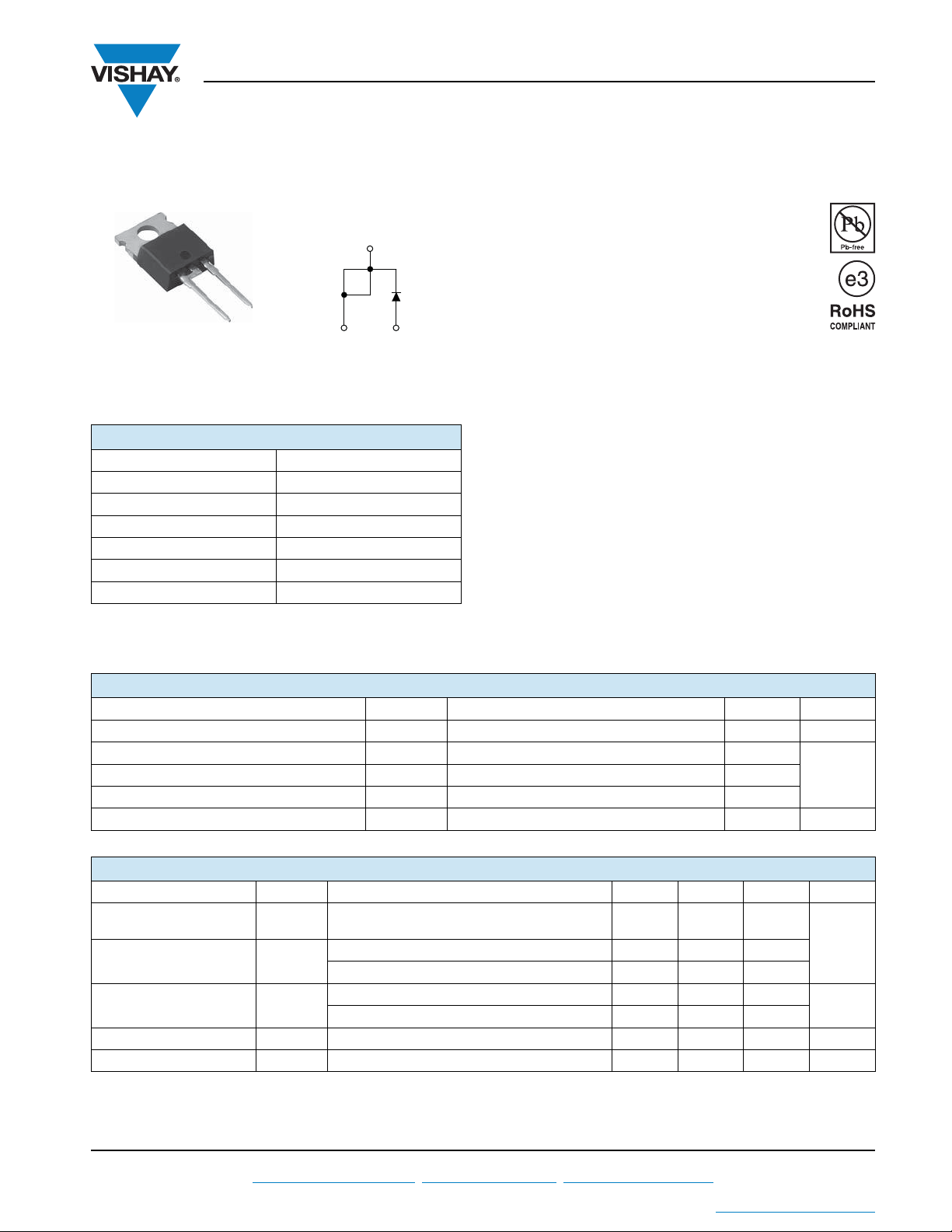
VS-MUR1520PbF
TO-220AC
Vishay Semiconductors
Ultrafast Rectifier, 15 A FRED Pt
PRODUCT SUMMARY
Package TO-220AC
I
F(AV)
V
R
V
at I
F
F
t
typ. See Recovery table
rr
T
max. 175 °C
J
Diode variation Single die
cathode
1
Cathode
200 V
1.05 V
Base
15 A
2
Anode
®
FEATURES
• Ultrafast recovery time
• Low forward voltage drop
• 175 °C operating junction temperature
• Low leakage current
3
• Compliant to RoHS Directive 2002/95/EC
• Designed and qualified for industrial level
DESCRIPTION/APPLICATIONS
VS-MUR1520PbF is the state of the art ultrafast recovery
rectifier specifically designed with optimized performance of
forward voltage drop and ultrafast recovery time.
The planar structure and the platinum doped life time
control, guarantee the best overall performance,
ruggedness and reliability characteristics.
These devices are intended for use in the output rectification
stage of SMPS, UPS, DC/DC converters as well as
freewheeling diode in low voltage inverters and chopper
motor drives.
Their extremely optimized stored charge and low recovery
current minimize the switching losses and reduce over
dissipation in the switching element and snubbers.
ABSOLUTE MAXIMUM RATINGS
PARAMETER SYMBOL TEST CONDITIONS MAX. UNITS
Peak repetitive reverse voltage V
Average rectified forward current I
Peak repetitive forward current I
Operating junction and storage temperatures T
F(AV)
FSM
, T
J
RRM
FM
Total device, rated VR, TC = 150 °C 15
Rated VR, square wave, 20 kHz, TC = 150 °C 30
Stg
200 V
200
- 65 to 175 °C
ANon-repetitive peak surge current I
ELECTRICAL SPECIFICATIONS (TJ = 25 °C unless otherwise specified)
PARAMETER SYMBOL TEST CONDITIONS MIN. TYP. MAX. UNITS
Breakdown voltage,
blocking voltage
Forward voltage V
Reverse leakage current I
Junction capacitance C
Series inductance L
,
V
BR
V
R
IR = 100 μA 200 - -
R
IF = 15 A - - 1.05
F
I
= 15 A, TJ = 150 °C - - 0.85
F
VR = VR rated - - 10
T
= 150 °C, VR = VR rated - - 500
J
VR = 200 V - 55 - pF
T
Measured lead to lead 5 mm from package body - 8.0 - nH
S
V
μA
Document Number: 94077 For technical questions within your region, please contact one of the following: www.vishay.com
Revision: 28-Apr-11 DiodesAmericas@vishay.com
This datasheet is subject to change without notice.
THE PRODUCT DESCRIBED HEREIN AND THIS DATASHEET ARE SUBJECT TO SPECIFIC DISCLAIMERS, SET FORTH AT
, DiodesAsia@vishay.com, DiodesEurope@vishay.com 1
www.vishay.com/doc?91000
VS-MUR1520PbF
Vishay Semiconductors
Ultrafast Rectifier, 15 A FRED Pt
DYNAMIC RECOVERY CHARACTERISTICS (TJ = 25 °C unless otherwise specified)
PARAMETER SYMBOL TEST CONDITIONS MIN. TYP. MAX. UNITS
IF = 1.0 A, dIF/dt = 50 A/μs, VR = 30 V - - 35
Reverse recovery time t
Peak recovery current I
Reverse recovery charge Q
rr
RRM
rr
= 25 °C
J
T
= 125 °C - 39 -
J
TJ = 25 °C - 1.6 -
T
= 125 °C - 4.1 -
J
= 15 A
I
F
/dt = 200 A/μs
dI
F
V
= 160 V
R
TJ = 25 °C - 19 -
T
= 125 °C - 90 -
J
THERMAL - MECHANICAL SPECIFICATIONS
PARAMETER SYMBOL TEST CONDITIONS MIN. TYP. MAX. UNITS
Maximum junction and
storage temperature range
Thermal resistance,
junction to case
Thermal resistance,
junction to ambient
Thermal resistance,
case to heatsink
Weight
Mounting torque
Marking device Case style TO-220AC MUR1520
, T
T
J
Stg
R
--1.5
thJC
R
thJA
R
thCS
Mounting surface, flat, smooth and
greased
®
-22-
- 65 - 175 °C
--50
-0.5-
-2.0- g
-0.07- oz.
6.0
(5.0)
-
12
(10)
kgf · cm
(lbf · in)
nsT
A
nC
°C/W
www.vishay.com For technical questions within your region, please contact one of the following: Document Number: 94077
2 DiodesAmericas@vishay.com
, DiodesAsia@vishay.com, DiodesEurope@vishay.com Revision: 28-Apr-11
This datasheet is subject to change without notice.
THE PRODUCT DESCRIBED HEREIN AND THIS DATASHEET ARE SUBJECT TO SPECIFIC DISCLAIMERS, SET FORTH AT
www.vishay.com/doc?91000
Ultrafast Rectifier, 15 A FRED Pt
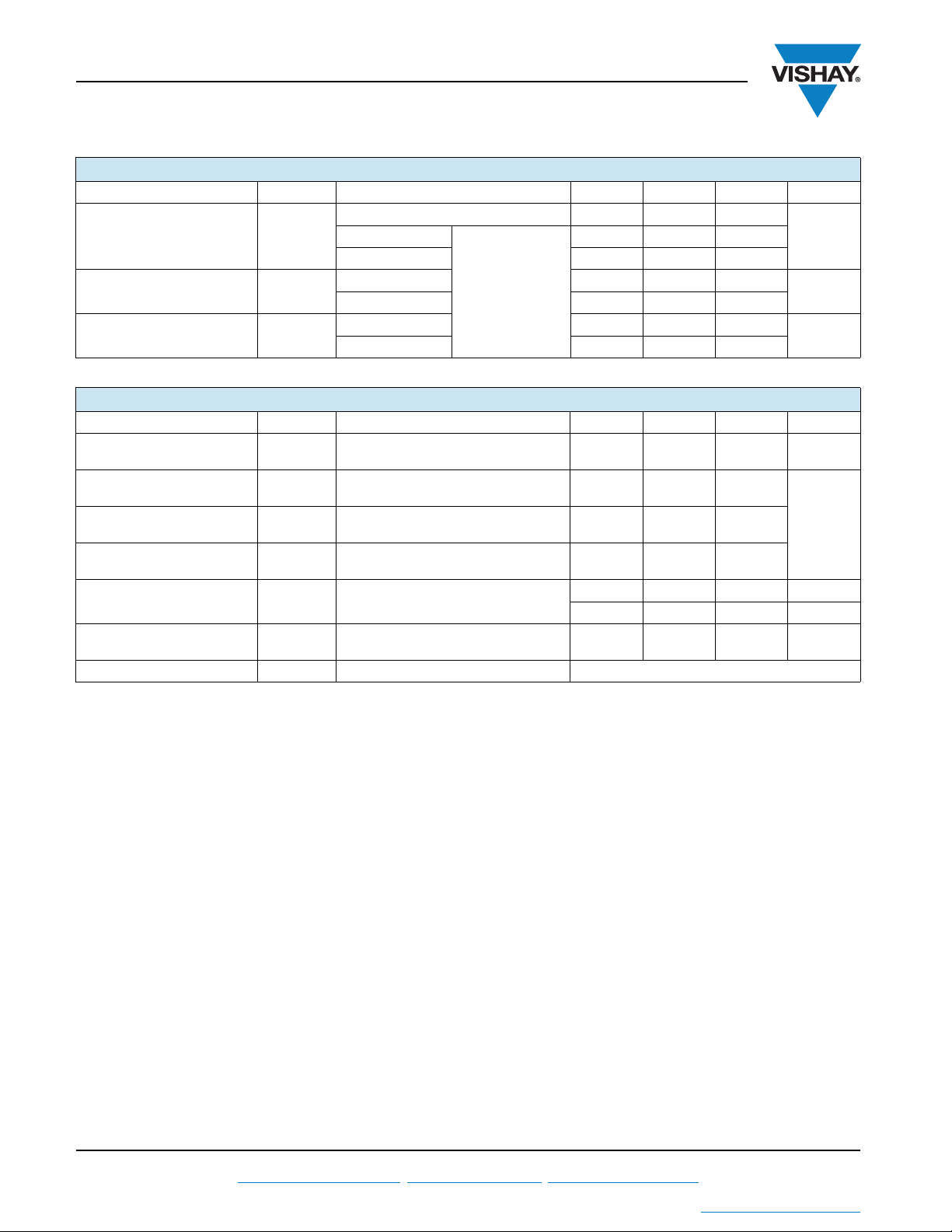
1
10
TJ = 175 °C
T
J
= 150 °C
T
J
= 25 °C
0 1.50.6 0.9
VF - Forward Voltage Drop (V)
I
F
- Instantaneous
Forward Current (A)
100
0.3 1.2
0.1
100
1000
0 10 100 1000
10
VR - Reverse Voltage (V)
C
T
- Junction Capacitance (pF)
TJ = 25 °C
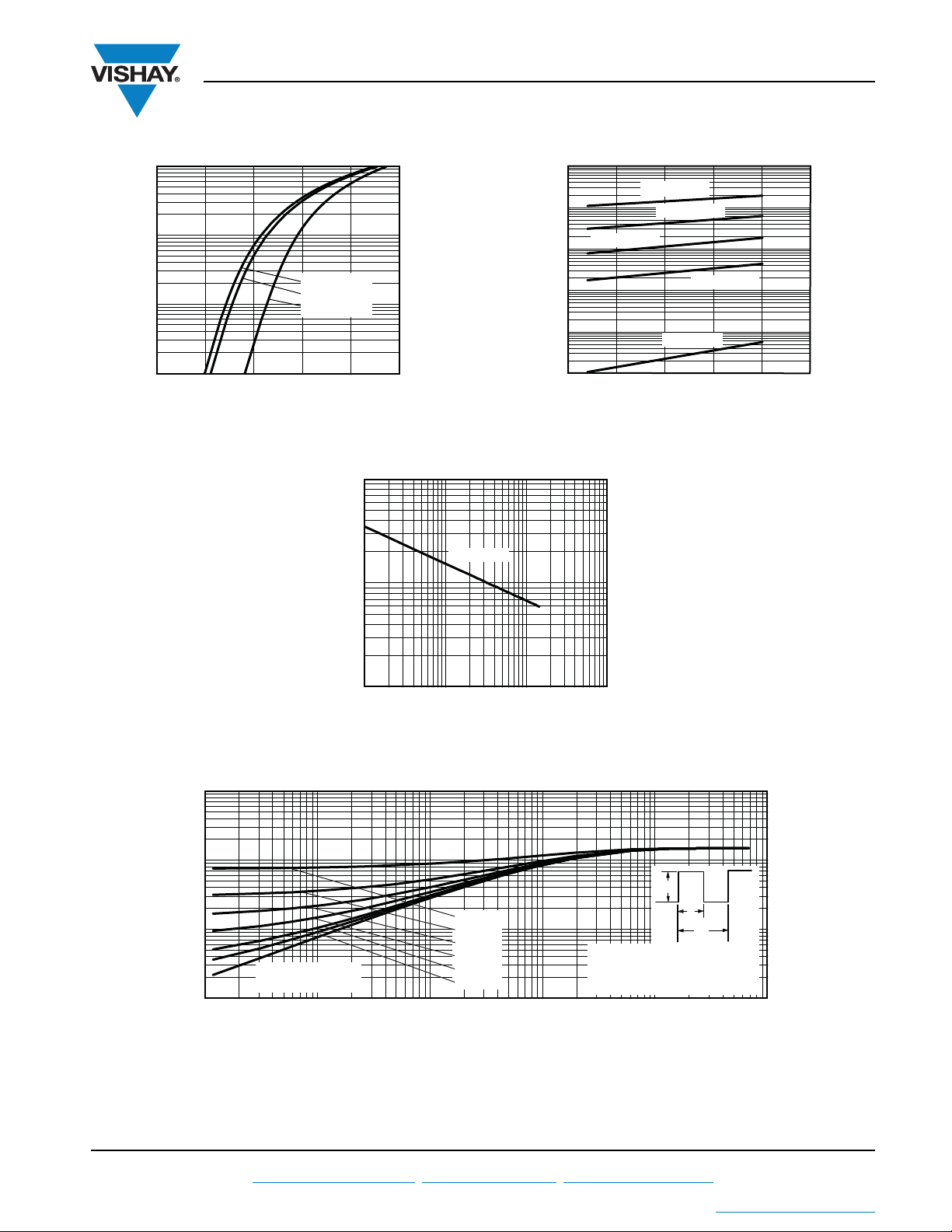
0.01
0.1
10
0.00001 0.0001 0.001 0.01 0.1 1
t1 - Rectangular Pulse Duration (s)
Z
thJC
- Thermal Impedance (°C/W)
.
.
P
DM
t
1
t
2
Notes:
1. Duty factor D = t
1/t2
2. Peak TJ = PDM x Z
thJC
+ T
C
1
Single pulse
(thermal resistance)
D = 0.50
D = 0.20
D = 0.10
D = 0.05
D = 0.02
D = 0.01
1000
100
VS-MUR1520PbF
®
Vishay Semiconductors
TJ = 175 °C
TJ = 150 °C
10
- Reverse Current (µA)
0.1
R
I
0.01
TJ = 125 °C
1
TJ = 25 °C
0 100 150
TJ = 100 °C
200 25050
VR - Reverse Voltage (V)
Fig. 1 - Typical Forward Voltage Drop Characteristics Fig. 2 - Typical Values of Reverse Current vs.
Reverse Voltage
Fig. 3 - Typical Junction Capacitance vs. Reverse Voltage
Document Number: 94077 For technical questions within your region, please contact one of the following: www.vishay.com
Revision: 28-Apr-11 DiodesAmericas@vishay.com
THE PRODUCT DESCRIBED HEREIN AND THIS DATASHEET ARE SUBJECT TO SPECIFIC DISCLAIMERS, SET FORTH AT
Fig. 4 - Maximum Thermal Impedance Z
, DiodesAsia@vishay.com, DiodesEurope@vishay.com 3
This datasheet is subject to change without notice.
thJC
Characteristics
www.vishay.com/doc?91000
 Loading...