

Page 1
MMKP 386
Vishay BCcomponents
AC and Pulse Double Metallized Polypropylene Film Capacitors
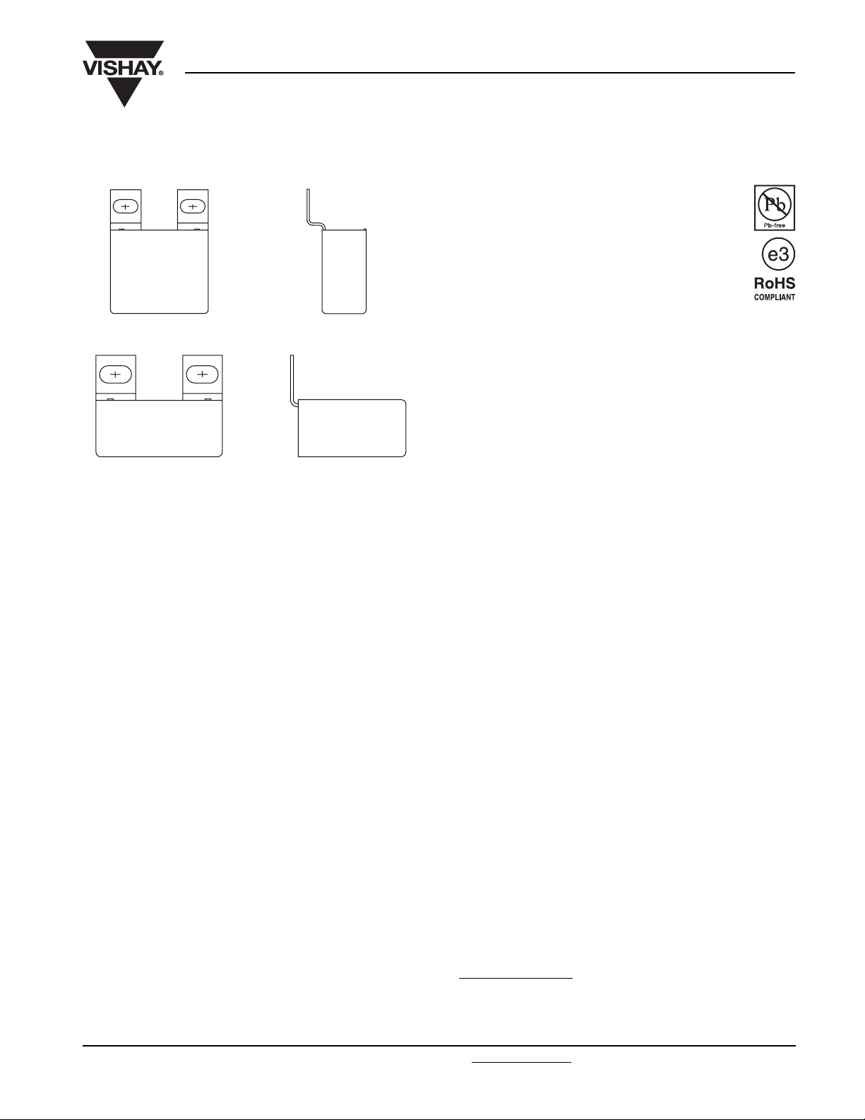
MMKP Radial Potted Type
Horizontally Mounted
Vertically Mounted
APPLICATIONS
Industrial motor control circuits, mounted directly on the
IGBT or GTO.
REFERENCE SPECIFICATIONS
IEC 60384-17
FEATURES
Low inductive construction
Low loss dielectric
Double sided metallized for high pulse ratings
RoHS compliant
ENCAPSULATION
Flame retardant plastic case (UL-class 94 V-0) and epoxy
resin
CLIMATIC TESTING CLASS ACC. TO IEC 60068-1
55/085/56
CAPACITANCE RANGE (E24 SERIES)
0.1to4.7µF
CAPACITANCE TOLERANCE
± 5 %; ± 10 %
TABS
Tinned coated copper
MARKING
C-value; tolerance; rated voltage; code for dielectric material;
code for factory of origin; manufacturer’s type, manufacturer;
year and week of manufacture
DIELECTRIC
Polypropylene film
ELECTRODES
Double metallized
CONSTRUCTION
Mono construction for 630 V version
Internal serial construction from 850 Vdc on
RATED (DC) VOLTAGE
630 V, 850 V, 1000 V, 1250 V, 1400 V, 1600 V, 2000 V,
2500 V
RATED (AC) VOLTAGE
220 V, 300 V, 350 V, 425 V, 500 V, 550 V, 700 V, 900 V
RATED PEAK-TO-PEAK VOLTAGE
630 V, 850 V, 1000 V, 1250 V, 1400 V, 1600 V, 2000 V,
2500 V
RATED (DC) TEMPERATURE
85 °C
RATED (AC) TEMPERATURE
85 °C
MAXIMUM APPLICATION TEMPERATURE
85 °C
PERFORMANCE GRADE
Grade 1 (long life)
STABILITY GRADE
Grade 2
DETAIL SPECIFICATION
For more detailed data and test requirements contact:
dc-film@vishay.com
Document Number: 28163 For technical questions, contact: dc-film@vishay.com
Revision: 21-Oct-08 269
www.vishay.com
Page 2
MMKP 386
Vishay BCcomponents
AC and Pulse Double Metallized Polypropylene
Film Capacitors MMKP Radial Potted Type
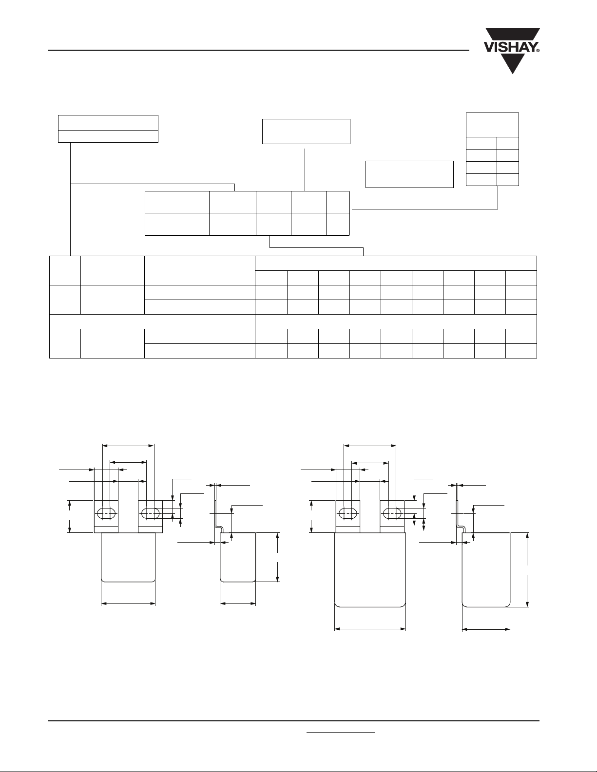
COMPOSITION OF CATALOG NUMBER
TYPE
386
BFC2 386 XX XX X
TYPE PACKAGING
386 Loose in box
386 Loose in box
2222
(1)
Old ordering code
Horizontally mounted ± 10 %2000308040506070
Vertically mounted ± 10 % 22 02 32 82 42 52 62 72
Horizontally mounted ± 5 %2101318141516171
Vertically mounted ± 5 % 23 03 33 83 43 53 63 73
(1)
MOUNTING
CONFIGURATION
386 XX XX X
CAPACITANCE
(numerically)
Example:
104 = 10 x 10 = 100 nF
PREFERRED TYPES
C-TOL. 630 V 850 V 1000 V 1250 V 1400 V 1600 V 2000 V 2500 V
ON REQUEST
MULTIPLIER
(nF)
0.1 2
13
10 4
100 5
Horizontally Mounted
P1 = 32.3 ± 1
15 ± 0.3
20 max.
P
= Pitch 1
1
P
= Pitch 2
2
11 min.
P2 = 22.7 ± 1
P
= 32.3 ± 1
1
P
= 22.7 ± 1
8 ± 0.2
6.3 ± 0.1
3.5 ± 1.0
l
Drawing A
0.8 ± 0.1
12.8 max.
W
15 ± 0.3
11 min.
20 max.
h
2
8 ± 0.2
6.3 ± 0.1
3.5 ± 1.0
l
Drawing B
1 ± 0.1
12.8 max.
h
W
www.vishay.com For technical questions, contact: dc-film@vishay.com
270 Revision: 21-Oct-08
Document Number: 28163
Page 3
MMKP 386
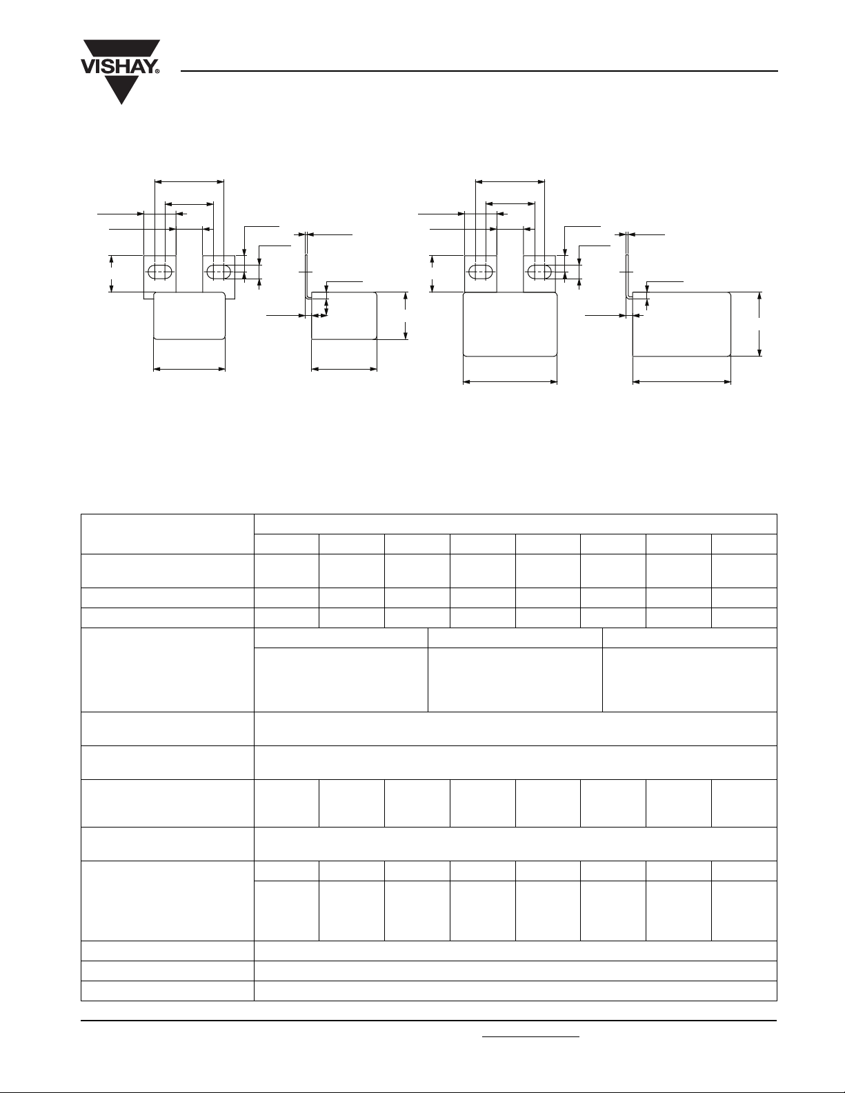
Vertically Mounted
P1 = 32.3 ± 1
P2 = 22.7 ± 1
15 ± 0.3
11 min.
17 max.
P
= Pitch 1
1
P
= Pitch 2
2
AC and Pulse Double Metallized Polypropylene
Film Capacitors MMKP Radial Potted Type
P
P
7.5 ± 0.5
6.3 ± 0.1
3 ± 1.0
l
0.8 ± 0.1
3.2 ± 1.0
h
Drawing A
15 ± 0.3
11 min.
17 max.
w
= 32.3 ± 1
1
= 22.7 ± 1
2
l
7.5 ± 0.5
Drawing B
Vishay BCcomponents
1 ± 0.1
6.3 ± 0.1
3.2 ± 1.0
3 ± 1.0
w
h
SPECIFIC REFERENCE DATA
0.15 µF
to 0.82 µF
< 5 x 10
< 10 x 10
< 25 x 10
> 5000 MΩ
> 30 000 MΩ
2000 V;
1 min
2840 V; 1 min
VALUE
0.1 µF
to 0.68 µF
-4
-4
-4
2240 V;
1 min
0.1 µF
to 0.56 µF
2560 V;
1 min
0.1 µF
to 0.47 µF
< 10 x 10
< 20 x 10
3200 V;
1 min
0.1 µF
to 0.27 µF
-4
-4
4000 V;
1 min
www.vishay.com
DESCRIPTION
Capacitance range
630 V 850 V 1000 V 1250 V 1400 V 1600 V 2000 V 2500 V
0.33 µF
to 4.7 µF
0.22 µF
to 2.7 µF
0.33 µF
to 1.8 µF
Maximum operating DC voltage 630 V 850 V 1000 V 1250 V 1400 V 1600 V 2000 V 2500 V
Maximum operating AC voltage 220 V 300 V 350 V 425 V 500 V 550 V 700 V 900 V
Tangent of loss angle ≤ 0.47 µF 0.56 µF ≤ C ≤ 1.0 µF C > 1.0 F
at 1 kHz
at 10 kHz
at 100 kHz
< 10 x 10
< 12 x 10
< 5 x 10
-4
-4
-4
R between terminals at 500 V;
1 min
R between terminals and case;
500 V; 1 min
Withstanding (DC) voltage
(cut off current 10 mA);
rise time 100 V/s
1000 V;
1 min
1360 V;
1 min
1600 V;
1 min
Withstanding (DC) voltage
between terminals and case
Maximum dU/dt (V/µs) 630 V 850 V 1000 V 1250 V 1400 V 1600 V 2000 V 2500 V
w x h x l = 22.0 x 30.5 x 33.5 250 650 1000 1500 2000 2400 2500 5500
w x h x l = 22.0 x 38.0 x 44.0 100 350 500 750 900 1000 1000 2000
w x h x l = 30.0 x 46.0 x 44.0 75 260 350 550 650 750 750 1500
ESR at 100 kHz 6 mΩ
ESL Typical 15 nH
Temperature range - 55 °C to + 85 °C
Document Number: 28163 For technical questions, contact: dc-film@vishay.com
Revision: 21-Oct-08 271
Page 4
MMKP 386
Vishay BCcomponents
AC and Pulse Double Metallized Polypropylene
Film Capacitors MMKP Radial Potted Type
U
= 630 V; U
Rdc
C
(µF)
Drawing A
0.33
0.39
0.47
0.56
0.68
0.82
1
1.2
Drawing B
1.5
1.8
2.2
2.7
3.3
3.9
4.7
• SPQ = Standard Packing Quantity
U
= 850 V; U
Rdc
C
(µF)
Drawing A
0.22
0.27
0.33
0.39
0.47
0.56
0.68
0.82
Drawing B
1.0
1.2
1.5
1.8
2.2
2.7
• SPQ = Standard Packing Quantity
= 1000 V; U
U
Rdc
C
(µF)
Drawing A
0.33
0.39
0.47
Drawing B
0.56
0.68
0.82
1.0
1.2
1.5
1.8
• SPQ = Standard Packing Quantity
www.vishay.com For technical questions, contact: dc-film@vishay.com
272 Revision: 21-Oct-08
= 220 V/U
Rac
DIMENSIONS
w xh xl
(mm)
22.0 x 30.5 x 33.5
22.0 x 38.0 x 44.0
30.0 x 46.0 x 44.0
= 300 V/U
Rac
DIMENSIONS
w xh xl
(mm)
22.0 x 30.5 x 33.5
22.0 x 38.0 x 44.0
30.0 x 46.0 x 44.0
= 350 V/U
Rac
DIMENSIONS
w xh xl
(mm)
22.0 x 30.5 x 33.5
22.0 x 38.0 x 44.0
30.0 x 46.0 x 44.0
pp
pp
= 630 V
= 850 V
= 1000 V
pp
MASS
(g)
39
38
38
37
37
36
35
35
60
58
56
54
86
83
80
MASS
(g)
39
39
38
38
37
37
36
35
61
59
58
91
88
85
MASS
(g)
36
35
34
60
59
57
55
88
84
80
CATALOG NUMBER BFC2 386 XXXXX AND PACKAGING
TRA Y PA C K AGING
C-tol. = ± 10 % SPQ
20334
20394
20474
20564
20684
20824
20105
20125
20155
20185
20225
20275
20335
20395
20475
CATALOG NUMBER BFC2 386 XXXXX AND PACKAGING
TRA Y PA C K AGING
C-tol. = ± 10 % SPQ
00224
00274
00334
00394
00474
00564
00684
00824
00105
00125
00155
00185
00225
00275
CATALOG NUMBER BFC2 386 XXXXX AND PACKAGING
TRA Y PA C K AGING
C-tol. = ± 10 % SPQ
30334
30394
30474
30564
30684
30824
30105
30125
30155
30185
56
42
36
56
42
36
56
42
36
Document Number: 28163
Page 5

MMKP 386
AC and Pulse Double Metallized Polypropylene
Film Capacitors MMKP Radial Potted Type
U
= 1250 V; U
Rdc
C
(µF)
Drawing A
0.15
0.18
0.22
0.27
Drawing B
0.33
0.39
0.47
0.56
0.68
0.82
• SPQ = Standard Packing Quantity
U
= 1400 V; U
Rdc
C
(µF)
Drawing A
0.1
0.12
0.15
Drawing B
0.18
0.22
0.27
0.33
0.39
0.47
0.56
0.68
• SPQ = Standard Packing Quantity
= 425 V/U
Rac
DIMENSIONS
w xh xl
(mm)
22.0 x 30.5 x 33.5
22.0 x 38.0 x 44.0
30.0 x 46.0 x 44.0
= 500 V/U
Rac
DIMENSIONS
w xh xl
(mm)
22.0 x 30.5 x 33.5
22.0 x 38.0 x 44.0
30.0 x 46.0 x 44.0
pp
pp
= 1250 V
MASS
= 1400 V
MASS
(g)
37
35
34
33
59
58
57
89
85
82
(g)
37
36
35
61
59
57
56
89
85
82
79
Vishay BCcomponents
CATALOG NUMBER BFC2 386 XXXXX AND PACKAGING
TRAY PACKAGING
C-tol. = ± 10 % SPQ
80154
80184
80224
80274
80334
80394
80474
80564
80684
80824
CATALOG NUMBER BFC2 386 XXXXX AND PACKAGING
TRAY PACKAGING
C-tol. = ± 10 % SPQ
40104
40124
40154
40184
40224
40274
40334
40394
40474
40564
40684
56
42
36
56
42
36
U
= 1600 V; U
Rdc
C
(µF)
Drawing A
0.1
0.12
0.15
Drawing B
0.18
0.22
0.27
0.33
0.39
0.47
0.56
• SPQ = Standard Packing Quantity
Document Number: 28163 For technical questions, contact: dc-film@vishay.com
Revision: 21-Oct-08 273
= 550 V/U
Rac
DIMENSIONS
w xh xl
(mm)
22.0 x 30.5 x 33.5
22.0 x 38.0 x 44.0
30.0 x 46.0 x 44.0
= 1600 V
pp
MASS
(g)
37
36
35
61
59
58
57
90
87
84
CATALOG NUMBER BFC2 386 XXXXX AND PACKAGING
TRAY PACKAGING
C-tol. = ± 10 % SPQ
50104
50124
40154
50184
50224
50274
50334
50394
50474
50564
56
42
36
www.vishay.com
Page 6

MMKP 386
Vishay BCcomponents
U
= 2000 V; U
Rdc
C
(µF)
Drawing A
0.1
0.12
Drawing B
0.15
0.18
0.22
0.27
0.33
0.39
0.47
• SPQ = Standard Packing Quantity
= 2500 V; U
U
Rdc
C
(µF)
Drawing B
0.1
0.12
0.15
0.18
0.22
0.27
• SPQ = Standard Packing Quantity
= 700 V/U
Rac
DIMENSIONS
w xh xl
(mm)
22.0 x 30.5 x 33.5
22.0 x 38.0 x 44.0
30.0 x 46.0 x 44.0
= 700 V/U
Rac
DIMENSIONS
w xh xl
(mm)
22.0 x 38.0 x 44.0
30.0 x 46.0 x 44.0
= 2000 V
pp
= 2500 V
pp
AC and Pulse Double Metallized Polypropylene
Film Capacitors MMKP Radial Potted Type
MASS
(g)
36
35
61
59
58
57
89
86
84
MASS
(g)
60
59
57
55
87
83
CATALOG NUMBER BFC2 386 XXXXX AND PACKAGING
TRA Y PA C K AGING
C-tol. = ± 10 % SPQ
60104
60124
60154
60184
60224
60274
60334
60394
60474
CATALOG NUMBER BFC2 386 XXXXX AND PACKAGING
TRA Y PA C K AGING
C-tol. = ± 10 % SPQ
70104
70124
70154
70184
70224
70274
56
42
36
42
36
MOUNTING
Normal Use
The capacitors are designed for direct mounting on IGBT or GTO.
Specific Method of Mounting to Withstand Vibration and Shock
In order to withstand vibration and shock tests, it must be ensured that the tabs are screwed tightly on the test board.
Storage Temperature
Storage temperature: T
Ratings and Characteristics Reference Conditions
Unless otherwise specified, all electrical values apply to an ambient temperature of 23 °C ± 1 °C, an atmospheric pressure of
86 kPa to 106 kPa and a relative humidity of 50 % ± 2 %.
For reference testing, a conditioning period shall be applied over 96 h ± 4 h by heating the products in a circulating air oven at
the rated temperature and a relative humidity not exceeding 20 %.
www.vishay.com For technical questions, contact: dc-film@vishay.com
274 Revision: 21-Oct-08
= - 25 °C to + 40 °C with RH maximum 80 % without condensation.
stg
Document Number: 28163
Page 7

MMKP 386
AC and Pulse Double Metallized Polypropylene
Vishay BCcomponents
Film Capacitors MMKP Radial Potted Type
CHARACTERISTICS
Capacitance as a function of ambient temperature (typical curve) Impedance as a function of frequency (typical curve)
4
(%)
ΔC/C
2
0
- 2
- 4
- 6
T
amb
(°C)
10080200- 20- 80
Max. DC and AC voltage as function of temperature Tangent of loss angle as a function of frequency (typical curve)
1.2
1
Factor
2
10
(Ω)
1
Impedance
10
0
10
-1
10
-2
10
-3
10
4
10
3
10
)
-4
220 nF
680 nF
5
10
6
10
7
10
f (Hz)
10
8
0.8
0.6
0.4
0.2
0
0
T
amb
Insulation resistance as a function of ambient temperature
(typical curve)
8
10
RC (s)
6
10
(°C)
2
Dissipation
Factor (x 10
10
680 nF
1
10
0
10
1006020- 20- 60
2
10
3
10
4
10
220 nF
5
f (Hz)
10
10
6
Max. allowed component temperature as a function of
ambient temperature
12
ΔT (°C)
8
4
4
10
0
40
6020 80 100
T
(°C)
amb
0
0
T
amb
(°C)
1005020- 20- 50
Document Number: 28163 For technical questions, contact: dc-film@vishay.com
www.vishay.com
Revision: 21-Oct-08 275
Page 8

MMKP 386
Vishay BCcomponents
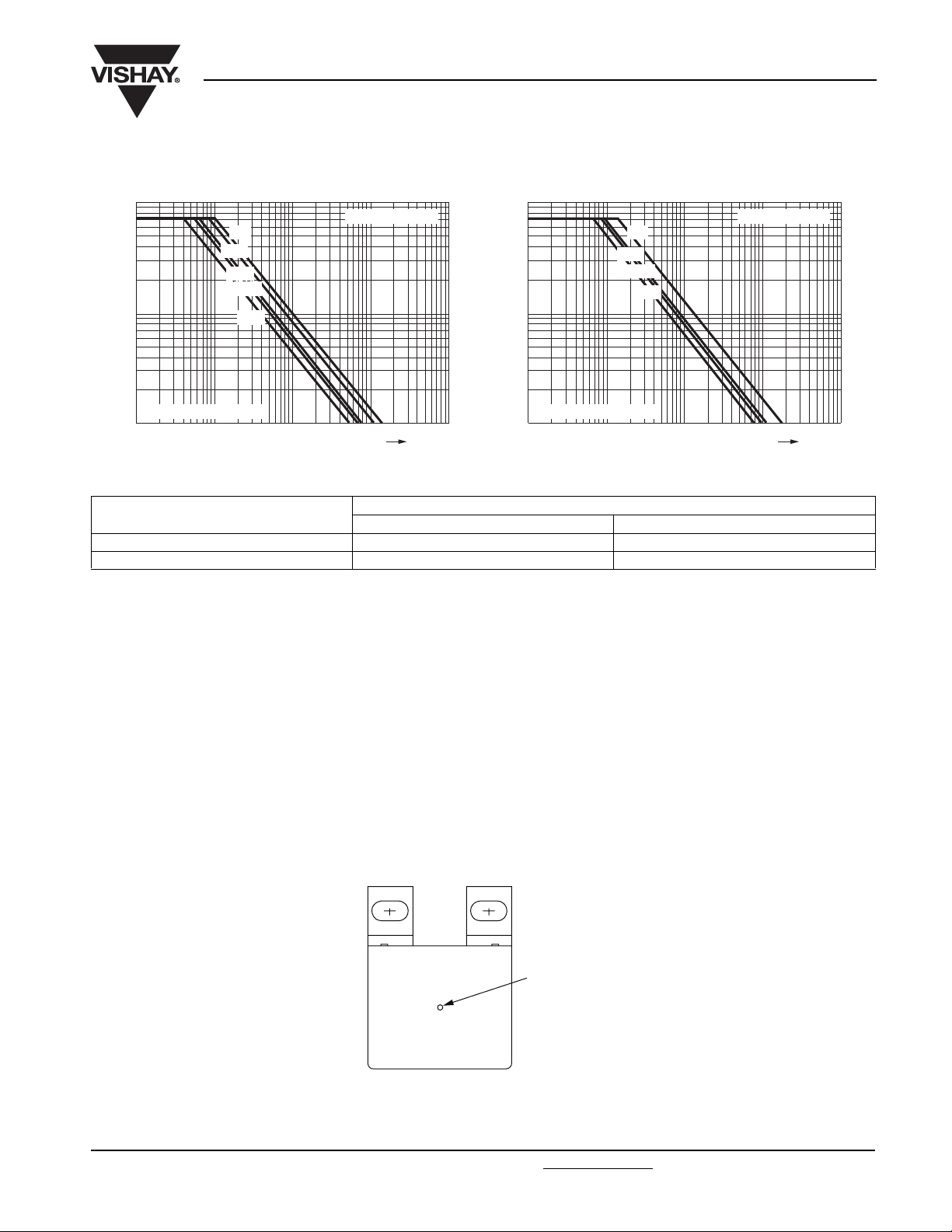
Max. AC voltage as a function of frequency Max. AC voltage as a function of frequency
3
10
(V)
RMS
V
0.33
2
10
T
≤ 75 °C, 630 Vdc
amb
1
10
3
10
Max. AC voltage as a function of frequency Max. AC voltage as a function of frequency
3
10
0.47
1.0
2.7
4.7
4
10
5
10
AC and Pulse Double Metallized Polypropylene
Film Capacitors MMKP Radial Potted Type
3
Capacitance in µF
6
10
f (Hz)
Capacitance in µF
10
7
10
(V)
RMS
V
0.22
0.47
2
10
1.0
1.5
2.7
T
≤ 75 °C, 850 Vdc
amb
1
10
3
10
3
10
4
10
5
10
Capacitance in µF
6
10
f (Hz)
Capacitance in µF
10
7
(V)
RMS
V
0.33
0.47
2
10
0.68
1.0
1.5
T
≤ 75 °C, 1000 Vdc
amb
1
10
3
10
4
10
5
10
6
10
f (Hz)
10
7
(V)
V
RMS
0.15
0.22
0.33
2
10
0.47
0.82
T
≤ 75 °C, 1250 Vdc
amb
1
10
3
10
4
10
5
10
6
10
f (Hz)
10
7
Max. AC voltage as a function of frequency Max. AC voltage as a function of frequency
3
10
Capacitance in µF
(V)
RMS
V
2
10
0.1
0.15
0.22
0.47
0.56
3
10
Capacitance in µF
(V)
V
RMS
0.1
0.15
0.23
2
10
0.47
0.56
T
≤ 75 °C, 1400 Vdc
amb
1
10
3
10
4
10
5
10
6
10
f (Hz)
10
7
T
≤ 75 °C, 1600 Vdc
amb
1
10
3
10
4
10
5
10
6
10
f (Hz)
10
7
www.vishay.com For technical questions, contact: dc-film@vishay.com
Document Number: 28163
276 Revision: 21-Oct-08
Page 9
MMKP 386
AC and Pulse Double Metallized Polypropylene
Vishay BCcomponents
Film Capacitors MMKP Radial Potted Type
Max. AC voltage as a function of frequency Max. AC voltage as a function of frequency
3
10
(V)
RMS
V
2
10
T
≤ 75 °C, 2000 Vdc
amb
1
10
3
10
0.1
0.15
0.22
0.23
0.47
4
10
5
10
Capacitance in µF
6
10
f (Hz)
10
7
HEAT CONDUCTIVITY (G) AS A FUNCTION OF BOX LENGTH AND CAPACITOR BODY THICKNESS IN mW/°C
W
max.
(mm)
22.0 75 100
30.0 - 140
BOX LENGTH 33.5 mm BOX LENGTH 44.0 mm
3
10
(V)
RMS
V
2
10
T
≤ 75 °C, 2500 Vdc
amb
1
10
3
10
0.1
0.15
0.22
0.23
4
10
HEAT CONDUCTIVITY (mW/°C)
Capacitance in µF
5
10
6
10
f (Hz)
10
7
POWER DISSIPATION AND MAXIMUM COMPONENT TEMPERATURE RISE
The power dissipation must be limited in order not to exceed the maximum allowed component temperature rise as a function of
the free air ambient temperature.
The power dissipation can be calculated according type detail specification “HQN-384-0/101: Technical Information Film
Capacitors”.
The component temperature rise (ΔT) can be measured (see section “Measuring the component temperature” for more details)
or calculated by ΔT = P/G:
• ΔT = Component temperature rise (°C)
• P = Power dissipation of the component (mW)
• G = Heat conductivity of the component (mW/°C)
MEASURING THE COMPONENT TEMPERATURE
A thermocouple must be attached to the capacitor body as in:
Thermocouple
The temperature is measured in unloaded (T
The temperature rise is given by ΔT = T
C
) and maximum loaded condition (TC).
amb
- T
.
amb
To avoid radiation or convection, the capacitor should be tested in a wind-free box.
Document Number: 28163 For technical questions, contact: dc-film@vishay.com
Revision: 21-Oct-08 277
www.vishay.com
Page 10

MMKP 386
Vishay BCcomponents
AC and Pulse Double Metallized Polypropylene
Film Capacitors MMKP Radial Potted Type
APPLICATION NOTE AND LIMITING CONDITIONS
These capacitors are not suitable for mains applications as across-the-line capacitors without additional protection, as described
hereunder. These mains applications are strictly regulated in safety standards and therefore electromagnetic interference
suppression capacitors conforming the standards must be used.
To select the capacitor for a certain application, the following conditions must be checked:
1. The peak voltage (U
2. The peak-to-peak voltage (U
3. The voltage pulse slope (dU/dt) shall not exceed the rated voltage pulse slope in an RC-circuit at rated voltage and without
ringing. If the pulse voltage is lower than the rated DC voltage, the rated voltage pulse slope may be multiplied by U
divided by the applied voltage.
For all other pulses following equation must be fulfilled:
T
2
dU
⎛⎞
--------
2
∫
0
⎝⎠
dt
dt U
T is the pulse duration.
The rated voltage pulse slope is valid for ambient temperatures up to 85 °C.
4. The maximum component surface temperature rise must be lower than the limits (see figure).
5. Since in circuits used at voltages over 280 V peak-to-peak the risk for an intrinsically active flammability after a capacitor
breakdown (short circuit) increases, it is recommended that the power to the component is limited to 100 times the values
mentioned in the table: “Heat Conductivity”
) shall not be greater than the rated DC voltage (U
P
) shall not be greater than the maximum U
P-P
dU
⎛⎞
--------
×<××
Rdc
⎝⎠
dt
rated
)
Rdc
to avoid the ionisation inception level
P-P
Rdc
and
Voltage Conditions
≤ 85 °C
ALLOWED VOLTAGES
Maximum continuous RMS voltage U
Maximum temperature RMS-overvoltage (< 24 h) 1.25 x U
Maximum peak voltage (V
O-P
) (< 2 s)
T
amb
1.6 x U
Rac
Rac
Rdc
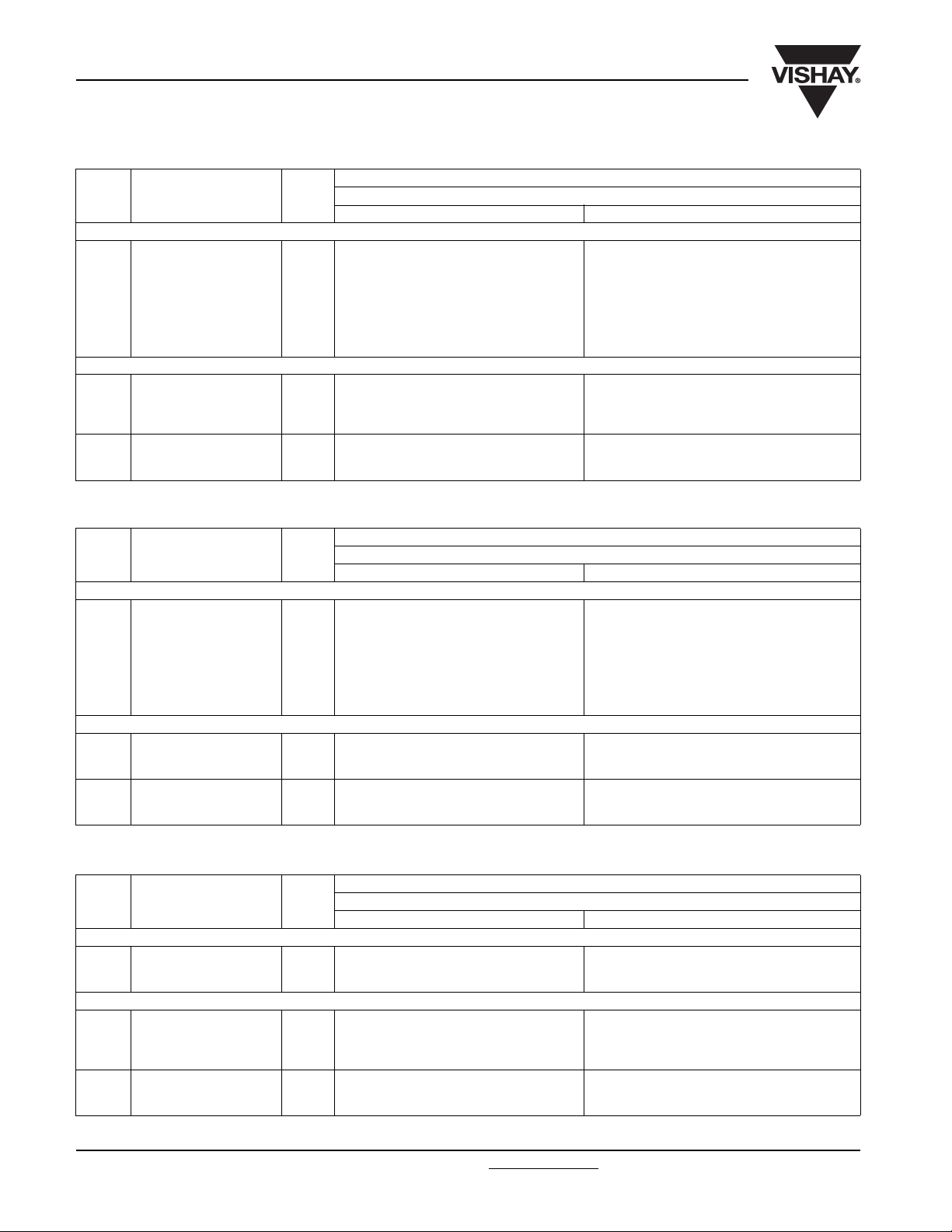
INSPECTION REQUIREMENTS
General Notes:
Sub-clause numbers of tests and performance requirements refer to the “Sectional Specification, Publication IEC 60384-17 and
Specific Reference Data”.
Group C Inspection Requirements
SUB-CLAUSE NUMBER AND TEST CONDITIONS PERFORMANCE REQUIREMENTS
SUB-GROUP C1A PART OF SAMPLE
OF SUB-GROUP C1
4.1 Dimensions (detail) As specified in chapters “General Data” of
4.3.1 Initial measurements Capacitance
Tangent of loss angle at 100 kHz
4.14 Component solvent resistance Isopropylalcohol at room temperature
Method: 2
Immersion time: 5 ± 0.5 min
Recovery time: Min. 1 h, max. 2 h
4.4.2 Final measurements Visual examination No visible damage
Capacitance |ΔC/C| ≤ 1 % of the value measured initially
Tangent of loss angle Increase of tan δ
www.vishay.com For technical questions, contact: dc-film@vishay.com
278 Revision: 21-Oct-08
this specification
Legible marking
≤ 0.001 for: 100 nF < C ≤ 470 nF or
≤ 0.0015 for: C > 470 nF
Compared to values measured in 4.3.1
Document Number: 28163
Page 11

MMKP 386
AC and Pulse Double Metallized Polypropylene
Vishay BCcomponents
Film Capacitors MMKP Radial Potted Type
SUB-CLAUSE NUMBER AND TEST CONDITIONS PERFORMANCE REQUIREMENTS
SUB-GROUP C1B OTHER PART OF
SAMPLE OF SUB-GROUP C1
4.6.1 Initial measurements Capacitance
Tangent of loss angle at 100 kHz
4.15 Solvent resistance of the marking Isopropylalcohol at room temperature
Method: 1
Rubbing material: Cotton wool
Immersion time: 5.0 ± 0.5 min
4.6 Rapid change of temperature θA = - 55 °C
θB = + 85 °C
5 cycles
Duration t = 30 min
4.7 Vibration Visual examination
4.7.2 Final inspection Visual examination No visible damage
4.9 Shock Mounting:
4.9.3 Final measurements Visual examination No visible damage
SUB-GROUP C1 COMBINED SAMPLE OF
SPECIMENS OF SUB-GROUPS
C1A AND C1B
4.10 Climatic sequence
4.10.2 Dry heat Temperature: + 85 °C
4.10.3 Damp heat cyclic
Test Db, first cycle
4.10.4 Cold Temperature: - 55 °C
4.10.6 Damp heat cyclic
Test Db, remaining cycles
4.10.6.2 Final measurements Voltage proof = U
Document Number: 28163 For technical questions, contact: dc-film@vishay.com
Revision: 21-Oct-08 279
Mounting:
See section “Mounting” for more information
Procedure B4
Frequency range: 10 Hz to 55 Hz
Amplitude: 0.75 mm or
Acceleration 98 m/s²
(whichever is less severe)
Total duration 6 h
See section “Mounting” for more information
Pulse shape: Half sine
Acceleration: 490 m/s²
Duration of pulse: 11 ms
Capacitance |ΔC/C| ≤ 1 % of the value measured in 4.6.1
Tangent of loss angle Increase of tan δ
Insulation resistance As specified in section “Insulation
Duration: 16 h
Duration: 2 h
for 1 min within 15 min
after removal from testchamber
Visual examination No visible damage
Capacitance |ΔC/C| ≤ 2 % of the value measured in
Tangent of loss angle Increase of tan δ
Insulation resistance ≥ 50 % of values specified in section
Rdc
No visible damage
Legible marking
No visible damage
≤ 0.001 for: 100 nF < C ≤ 470 nF or
≤ 0.0015 for: C > 470 nF
Compared to values measured in 4.6.1
Resistance” of this specification
No breakdown of flashover
Legible marking
4.4.2 or 4.9.3
≤ 0.001 for: 100 nF < C ≤ 470 nF or
≤ 0.0015 for: C > 470 nF
Compared to values measured in 4.3.1. or
4.6.1
“Insulation Resistance” of this specification
www.vishay.com
Page 12

MMKP 386
Vishay BCcomponents
AC and Pulse Double Metallized Polypropylene
Film Capacitors MMKP Radial Potted Type
SUB-CLAUSE NUMBER AND TEST CONDITIONS PERFORMANCE REQUIREMENTS
SUB-GROUP C2
4.11 Damp heat steady state 56 days, 40 °C, 90 % to 95 % RH
no load
4.11.1 Initial measurements Capacitance
Tangent of loss angle at 1 kHz
4.11.3 Final measurements Voltage proof = U
after removal from testchamber
Visual examination No visible damage
Capacitance |ΔC/C| ≤ 1 % of the value measured in
Tangent of loss angle Increase of tan δ
Insulation resistance ≥ 50 % of values specified in section
SUB-GROUP C3A
4.12.1 Endurance test at 50 Hz
alternating voltage
4.12.1.1 Initial measurements Capacitance
4.12.1.3 Final measurements Visual examination No visible damage
SUB-GROUP C4
4.2.6 Temperature characteristics
Initial measurements
Intermediate measurements
Final measurements
4.13 Charge and discharge 10 000 cycles
4.13.1 Initial measurements Capacitance
4.13.3 Final measurements Capacitance |ΔC/C| ≤ 1 % compared to values measured
www.vishay.com For technical questions, contact: dc-film@vishay.com
280 Revision: 21-Oct-08
Duration: 2000 h
Voltage: 1.25 x U
Tangent of loss angle at 100 kHz
Capacitance |ΔC/C| ≤ 5 % compared to values measured
Tangent of loss angle Increase of tan δ
Insulation resistance ≥ 50 % of values specified in section
Capacitance
Capacitance at - 55 °C
Capacitance at 20 °C
Capacitance at + 85 °C
Capacitance
Insulation resistance
Charged to U
Discharge resistance:
R
Tangent of loss angle at 100 kHz
Tangent of loss angle Increase of tan δ
Insulation resistance ≥ 50 % of values specified in section
for 1 min within 15 min
Rdc
at 85 °C
Rac
Rdc
U
=
Rdc
---------------------------------------5 x C dU dt⁄()
No breakdown of flashover
Legible marking
4.11.1.
≤ 0.001 for: 100 nF < C ≤ 470 nF or
≤ 0.0015 for: C ≤ 470 nF
Compared to values measured in 4.11.1
“Insulation Resistance” of this specification
Legible marking
in 4.12.1.1
≤ 0.001 for: 100 nF < C ≤ 470 nF or
≤ 0.0015 for: C > 470 nF
Compared to values measured in 4.12.1.1
“Insulation Resistance” of this specification
For - 55 °C to + 20 °C:
+ 1 % ≤ |ΔC/C| ≤ 3.75 % or
for 20 °C to 105 °C:
- 6 % ≤ |ΔC/C| ≤ 0 %
As specified in section “Capacitance” of this
specification.
As specified in section “Insulation
Resistance” of this specification
in 4.13.1
≤ 0.001 for: 100 nF < C ≤ 470 nF or
≤ 0.0015 for: C > 470 nF
Compared to values measured in 4.13.1
“Insulation Resistance” of this specification
Document Number: 28163
Page 13

Legal Disclaimer Notice
Vishay
Disclaimer
All product specifications and data are subject to change without notice.
Vishay Intertechnology, Inc., its affiliates, agents, and employees, and all persons acting on its or their behalf
(collectively, “Vishay”), disclaim any and all liability for any errors, inaccuracies or incompleteness contained herein
or in any other disclosure relating to any product.
Vishay disclaims any and all liability arising out of the use or application of any product described herein or of any
information provided herein to the maximum extent permitted by law. The product specifications do not expand or
otherwise modify Vishay’s terms and conditions of purchase, including but not limited to the warranty expressed
therein, which apply to these products.
No license, express or implied, by estoppel or otherwise, to any intellectual property rights is granted by this
document or by any conduct of Vishay.
The products shown herein are not designed for use in medical, life-saving, or life-sustaining applications unless
otherwise expressly indicated. Customers using or selling Vishay products not expressly indicated for use in such
applications do so entirely at their own risk and agree to fully indemnify Vishay for any damages arising or resulting
from such use or sale. Please contact authorized Vishay personnel to obtain written terms and conditions regarding
products designed for such applications.
Product names and markings noted herein may be trademarks of their respective owners.
Document Number: 91000 www.vishay.com
Revision: 18-Jul-08 1
 Loading...