

DC Film Capacitor
MKT Radial Potted Type
MKT 370
Vishay BCcomponents
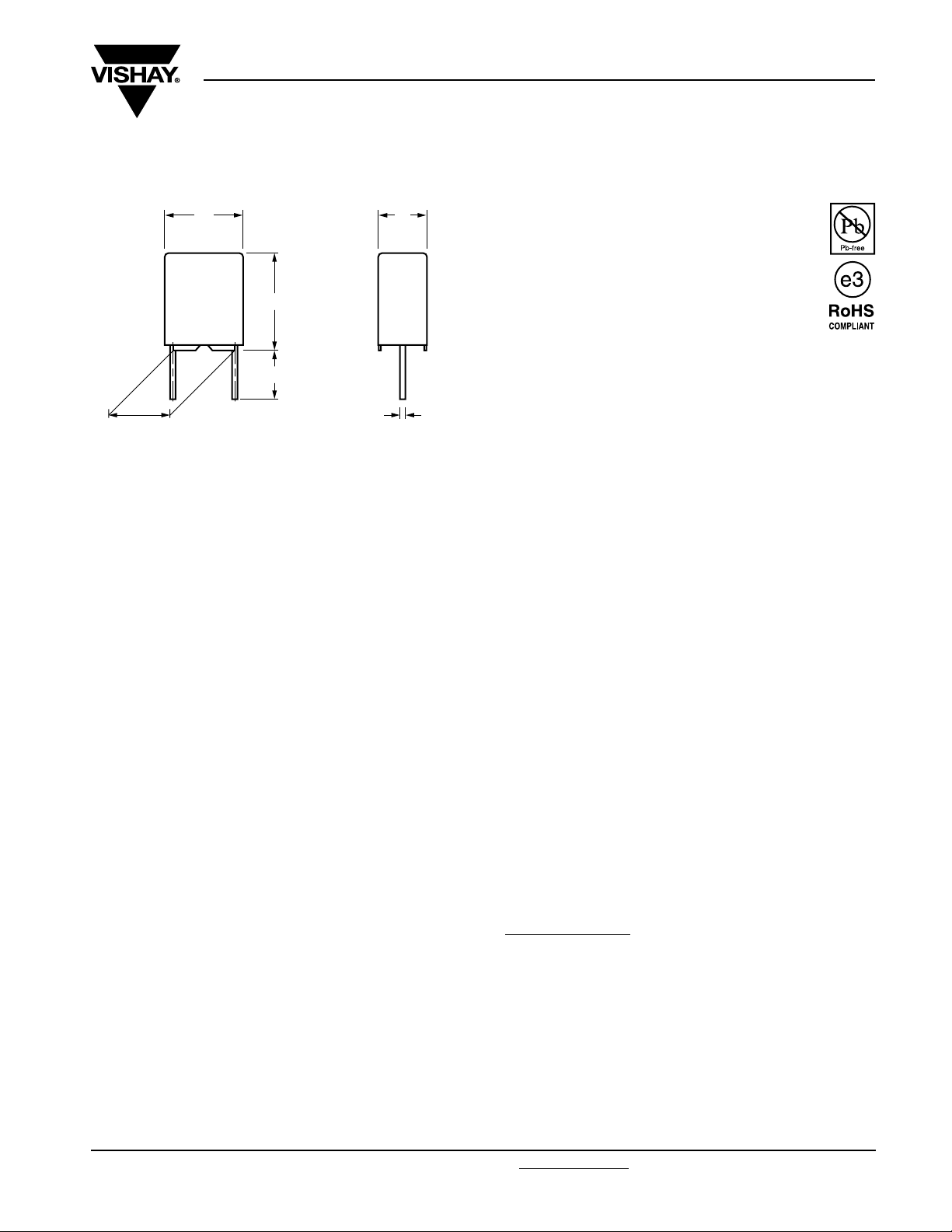
P ± 0.3
Dimensions in mm
l
h
l
t
w
Ø d
t
APPLICATIONS
Blocking and coupling, bypass and energy reservoir,
telecom, industrial, consumer
REFERENCE STANDARDS
IEC 60384-2
MARKING
C-value; tolerance; rated voltage; manufacturer’s symbol;
year and week of manufacturer; manufacturer’s type
FEATURES
Available taped and loose in box
RoHS compliant
ENCAPSULATION
Flame retardant plastic case and epoxy resin
(UL-class 94 V-0)
CLIMATIC TESTING CLASS ACC. TO IEC 60068-1
55/100/56
CAPACITANCE RANGE (E12 SERIES)
0.00068 µF to 1.5 µF
CAPACITANCE TOLERANCE
± 10 %, ± 5 %
LEADS
Tinned wire
RATED TEMPERATURE
85 °C
DIELECTRIC
Polyester film
MAXIMUM APPLICATION TEMPERATURE
100 °C
ELECTRODES
Metallized
PERFORMANCE GRADE
Grade 1 (long life)
CONSTRUCTION
Mono construction
Series construction for 630 V 0.00068 µF ~ 0.0018 µF
DETAIL SPECIFICATION
For more detailed data and test requirements contact:
dc-film@vishay.com
RATED (DC) VOLTAGE
Standard size: 63 V, 100 V, 250 V, 400 V
Compact size: 100 V, 250 V, 400 V, 630 V
RATED (AC) VOLTAGE
Standard size: 40 V, 63 V, 160 V, 220 V
Compact size: 40 V, 63 V, 160 V, 220 V
Document Number: 28108 For technical questions, contact: dc-film@vishay.com
Revision: 08-Dec-08 77
www.vishay.com
MKT 370
Vishay BCcomponents
DC Film Capacitor
MKT Radial Potted Type
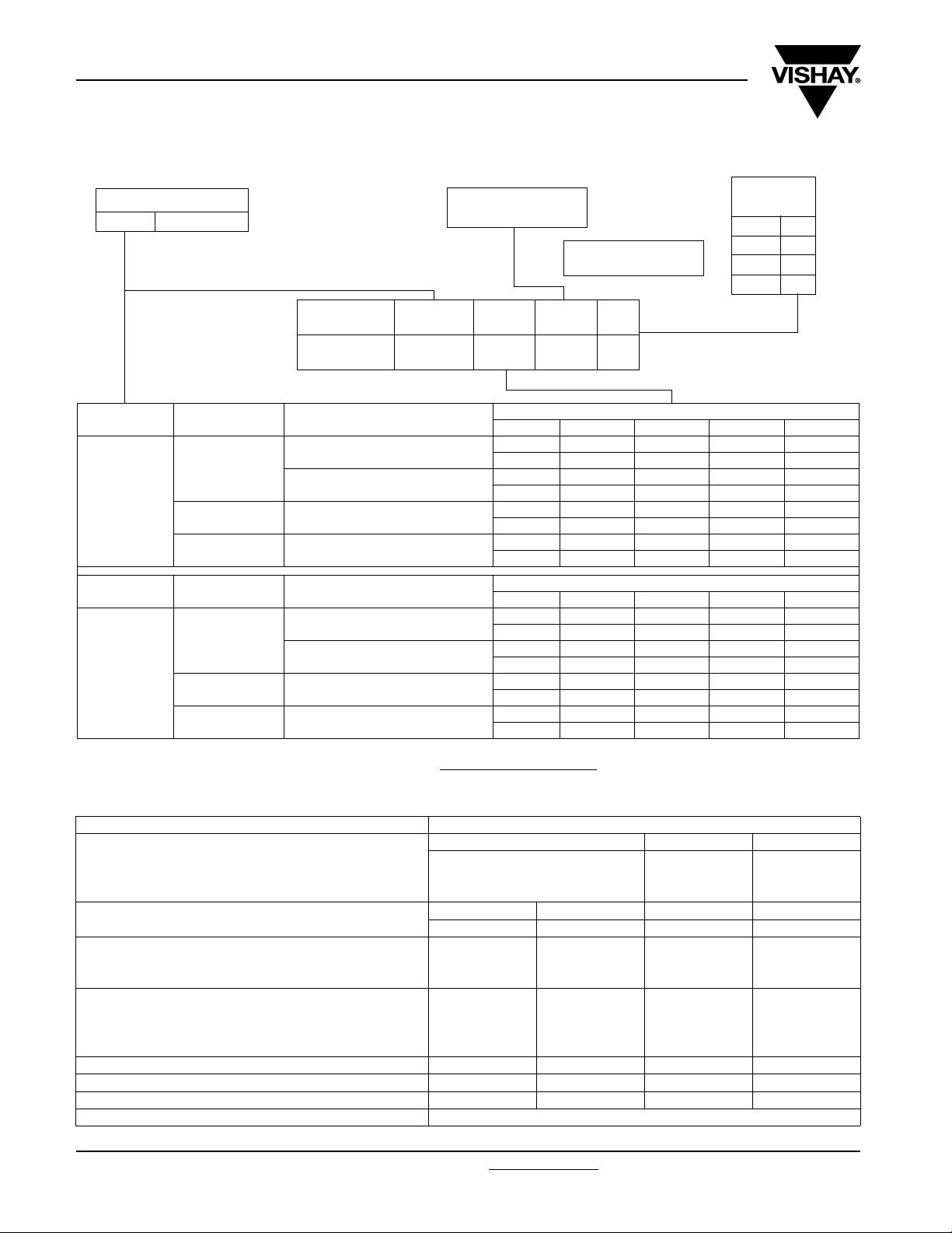
COMPOSITION OF CATALOG NUMBER
TYPE AND PITCHES
370 5.08 mm
CAPACITANCE
(numerically)
Example:
104 = 10 x 10 = 100 nF
BFC2 370 XX YY Y
2222
(*) Old ordering number
TYPE PACKAGING LEAD CONFIGURATION
Lead length 4.0 + 1.0/- 0.5 mm
Loose in box
370
(standard size)
TYPE PACKAGING LEAD CONFIGURATION
370
(compact size)
Notes
(1)
For detailed tape specifications refer to packaging information: www.vishay.com/doc?28139 or end of catalog
(2)
SPQ = Standard Packing Quantity
Taped on reel
Ammopack
Loose in box
Taped on reel
Ammopack
Lead length 26.0 ± 2.0 mm
H = 18.5 mm; P0= 12.7 mm;
(1)
Reel diameter = 356 mm
(1)
H = 18.5 mm; P0= 12.7 mm
Lead length 4.0 + 1.0/- 0.5 mm
Lead length 26.0 ± 2.0 mm
H = 18.5 mm; P0= 12.7 mm;
(1)
Reel diameter = 356 mm
(1)
H = 18.5 mm; P0= 12.7 mm
(*)
370 XX YY Y
PREFERRED TYPES
C-TOL. 63 V 100 V 250 V 400 V
± 10 %11214151
± 5 %12224252
± 10 %15254555
± 5 %16264656
± 10 %18284858
± 5 %19294959
± 10 %75853565
± 5 %76863666
PREFERRED TYPES
C-TOL. 100 V 250 V 400 V 630 V
± 10 %CEEEFEGE
± 5 %CFEF FFGF
± 10 %CHEHFHGH
± 5 %CIEIFIGI
± 10 %CLELFLGL
± 5 %CMEM FMGM
± 10 %CBEBFBGB
± 5 %CCEC FCGC
MULTIPLIER
(nF)
0.1 2
13
10 4
100 5
SPECIFIC REFERENCE DATA (STANDARD SIZE)
DESCRIPTION VALUE
Tangent of loss angle: at 1 kHz at 10 kHz at 100 kHz
C ≤ 0.1 µF ≤ 75 x 10
0.1 µF < C ≤ 0.47 µF ≤ 75 x 10
0.47 µF < C ≤ 1.5 µF ≤ 75 x 10
Rated voltage pulse slope (dU/dt)
R between leads, for C ≤ 0.33 µF
at 10 V; 1 min > 15 000 MΩ
at 100 V; 1 min > 15 000 MΩ > 30 000 MΩ > 30 000 MΩ
RC between leads
0.33 µF < C ≤ 1.0 µF at 10 V; 1 min > 5000 s
C > 1.0 µF at 10 V; 1 min > 1000 s
C > 0.33 µF at 100 V; 1 min > 5000 s
R between interconnecting leads and case (foil method) > 30 000 MΩ > 30 000 MΩ > 30 000 MΩ > 30 000 MΩ
Withstanding (DC) voltage (cut off current 10 mA); 100 V; 1 min 160 V; 1 min 400 V; 1 min 640 V; 1 min
Withstanding (DC) voltage between leads and case 200 V; 1 min 200 V; 1 min 500 V; 1 min 800 V; 1 min
Maximum application temperature 100 °C
www.vishay.com For technical questions, contact: dc-film@vishay.com
78 Revision: 08-Dec-08
at
R
63 Vdc 100 Vdc 250 Vdc 400 Vdc
60 V/µs 110 V/µs 330 V/µs 630 V/µs
-4
-4
-4
≤ 130 x 10
≤ 130 x 10
≤ 130 x 10
-4
≤ 250 x 10
-4
≤ 300 x 10
-4
-
Document Number: 28108
-4
-4
MKT 370
DC Film Capacitor
Vishay BCcomponents
MKT Radial Potted Type
SPECIFIC REFERENCE DATA (COMPACT SIZE)
DESCRIPTION VALUE
Tangent of loss angle: at 1 kHz at 10 kHz at 100 kHz
C ≤ 0.1 µF ≤ 75 x 10
0.1 µF < C ≤ 0.47 µF ≤ 75 x 10
C > 0.47 µF ≤ 75 x 10
Rated voltage pulse slope (dU/dt)
at
R
100 Vdc 250 Vdc 400 Vdc 630 Vdc
37 V/µs 44 V/µs 200 V/µs 540 V/µs
-4
-4
-4
≤ 130 x 10
≤ 130 x 10
≤ 130 x 10
R between leads, for C ≤ 0.33 µF
at 100 V; 1 min > 15 000 MΩ > 30 000 MΩ > 30 000 MΩ > 30 000 MΩ
RC between leads
C > 0.33 µF at 100 V; 1 min > 5000 s
R between interconnecting leads and case (foil method) > 30 000 MΩ > 30 000 MΩ > 30 000 MΩ > 30 000 MΩ
Withstanding (DC) voltage (cut off current 10 mA);
160 V; 1 min 400 V; 1 min 640 V; 1 min 1008 V; 1 min
Withstanding (DC) voltage between leads and case 200 V; 1 min 500 V; 1 min 800 V; 1 min 1260 V; 1 min
Maximum application temperature 100 °C
U
= 63 V; U
Rdc
Rac
= 40 V
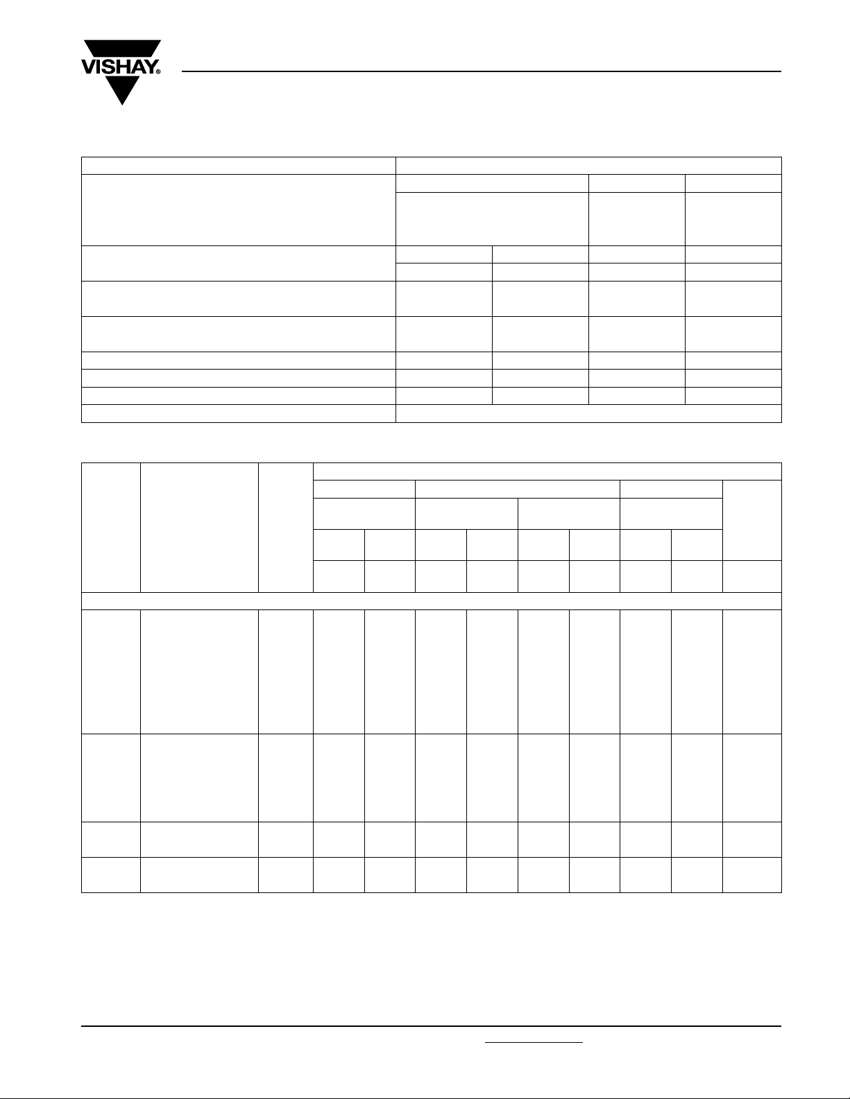
CATALOG NUMBER BFC2 370 XXYYY AND PACKAGING
AMMOPACK LOOSE IN BOX REEL
C
(µF)
DIMENSIONS
w x h x l
(mm)
Pitch = 5.08 ± 0.30 mm; d
MASS
(1)
(g)
= 0.50 ± 0.05 mm
t
H = 18.5 mm;
= 12.7 mm
P
0
C-tol. =
± 10 %
(SPQ)XX(SPQ)XX(SPQ)XX(SPQ)XX(SPQ)XX(SPQ)XX(SPQ)XX(SPQ)
XX
C-tol. =
± 5 %
Short leads Long leads
C-tol. =
± 10 %
C-tol. =
± 5 %
C-tol. =
± 10 %
C-tol. =
± 5 %
0.056
0.068 683
0.082 823
0.1 104
2.5 x 6.5 x 7.2 0.18
0.12 124
75…
(2000)
76…
(2000)
11…
(2000)
12…
(2000)
15…
(1000)
16…
(1000)
0.15 154
0.18 184
0.22
0.27 274
0.33 334
3.5 x 8.0 x 7.2 0.3
0.39 394
75…
(1500)
76…
(1500)
11…
(2000)
12…
(2000)
15…
(1000)
16…
(1000)
0.47 474
0.56
0.68 684
0.82
1.0 105
Note
(1)
Weight for short lead products only
4.5 x 9.0 x 7.2 0.42
6.0 x 11.0 x 7.2 0.64
75…
(1000)
75…
(750)
76…
(1000)
76…
(750)
11…
(2000)
11…
(2000)
12…
(2000)
12…
(2000)
15…
(1000)
15…
(1000)
16…
(1000)
16…
(1000)
C-tol. =
± 10 %
18…
(2000)
18…
(1500)
18…
(1000)
18…
(1000)
-4
≤ 250 x 10
-4
≤ 300 x 10
-4
-
C-VALUE
C-tol. =
± 5 %
19…
(2000)
19…
(1500)
19…
(1000)
19…
(1000)
..YYY
563
224
564
824
-4
-4
Document Number: 28108 For technical questions, contact: dc-film@vishay.com
www.vishay.com
Revision: 08-Dec-08 79
MKT 370
Vishay BCcomponents
DC Film Capacitor
MKT Radial Potted Type
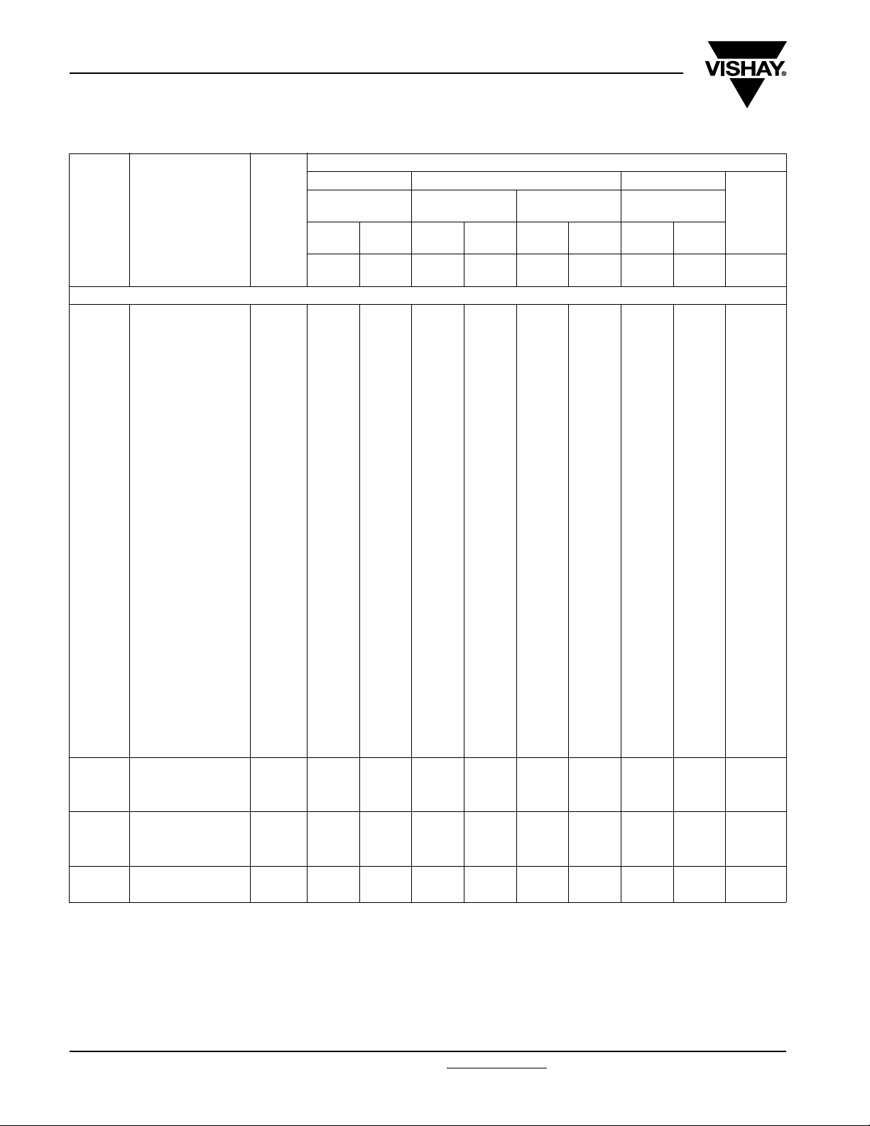
U
= 100 V; U
Rdc
C
(µF)
Pitch = 5.08 ± 0.30 mm; d
0.001
0.0012 122
0.0015 152
0.0018 182
0.0022 222
0.0027 272
0.0033 332
0.0039 392
0.0047 472
0.0056 562
0.0068 682
0.0082 822
0.010 103
0.012 123
0.015 153
0.018 183
0.022 223
0.027 273
0.033 333
0.039 393
0.047 473
0.056 563
0.068 683
0.082 823
0.10 104
0.12
0.15 154
0.18 184
0.22
0.27 274
0.33 334
0.39
0.47 474
Note
(1)
Weight for short lead products only
= 63 V (standard size)
Rac
DIMENSIONS
w x h x l
(mm)
= 0.50 ± 0.05 mm
t
2.5 x 6.5 x 7.2 0.18
3.5 x 8.0 x 7.2 0.30
4.5 x 9.0 x 7.2 0.42
6.0 x 11.0 x 7.2 0.64
MASS
(g)
CATALOG NUMBER BFC2 370 XXYYY AND PACKAGING
AMMOPACK LOOSE IN BOX REEL
H = 18.5 mm;
P
= 12.7 mm
(1)
0
C-tol. =
± 10 %
(SPQ)XX(SPQ)XX(SPQ)XX(SPQ)XX(SPQ)XX(SPQ)XX(SPQ)XX(SPQ)
85...
(2000)
85...
(1500)
85...
(1000)
85...
(750)
C-tol. =
± 5 %
XX
86...
(2000)
86...
(1500)
86...
(1000)
86...
(750)
Short leads Long leads
C-tol. =
± 10 %
21...
(2000)
21...
(2000)
21...
(2000)
21...
(2000)
C-tol. =
± 5 %
22...
(2000)
22...
(2000)
22...
(2000)
22...
(2000)
C-tol. =
± 10 %
25...
(1000)
25...
(1000)
25...
(1000)
25...
(1000)
C-tol. =
± 5 %
26...
(1000)
26...
(1000)
26...
(1000)
26...
(1000)
C-tol. =
± 10 %
28...
(2000)
28...
(1500)
28...
(1000)
28...
(1000)
C-VALUE
C-tol. =
± 5 %
29...
(2000)
29...
(1500)
29...
(1000)
29...
(1000)
..YYY
102
124
224
394
www.vishay.com For technical questions, contact: dc-film@vishay.com
80 Revision: 08-Dec-08
Document Number: 28108
MKT 370
DC Film Capacitor
Vishay BCcomponents
MKT Radial Potted Type
U
= 100 V; U
Rdc
C
(µF)
Pitch = 5.08 ± 0.30 mm; d
0.12
0.15 154
0.18 184
0.22 224
0.27 274
0.33 334
0.39
0.47 474
0.56 6.0 x 11.0 x 7.2 0.64
Note
(1)
Weight for short lead products only
= 250 V; U
U
Rdc
C
(µF)
Pitch = 5.08 ± 0.30 mm; d
0.001
0.0012 122
0.0015 152
0.0018 182
0.0022 222
0.0027 272
0.0033 332
0.0039 392
0.0047 472
0.0056 562
0.0068 682
0.0082 822
0.010 103
0.012 123
0.015 153
0.018 183
0.022
0.027 273
0.033 333
0.039
0.047 473
0.056 563
0.068
0.082 823
0.10 104
Note
(1)
Weight for short lead products only
Document Number: 28108 For technical questions, contact: dc-film@vishay.com
Revision: 08-Dec-08 81
= 40 V (compact size)
Rac
DIMENSIONS
w x h x l
(mm)
t
= 0.50 ± 0.05 mm
MASS
(g)
3.5 x 8.0 x 7.2 0.30
4.5 x 9.0 x 7.2 0.42
= 160 V (standard size)
Rac
DIMENSIONS
w x h x l
(mm)
t
= 0.50 ± 0.05 mm
MASS
(g)
2.5 x 6.5 x 7.2 0.18
3.5 x 8.0 x 7.2 0.30
4.5 x 9.0 x 7.2 0.42
6.0 x 11.0 x 7.2 0.64
CATALOG NUMBER BFC2 370 XXYYY AND PACKAGING
AMMOPACK LOOSE IN BOX REEL
H = 18.5 mm;
= 12.7 mm
P
(1)
0
C-tol. =
± 10 %
(SPQ)XX(SPQ)XX(SPQ)XX(SPQ)XX(SPQ)XX(SPQ)XX(SPQ)XX(SPQ)
CB...
(1500)
CB...
(1000)
CB...
(750)
XX
C-tol. =
± 5 %
CC...
(1500)
CC...
(1000)
CC...
(750)
Short leads Long leads
C-tol. =
± 10 %
CE...
(2000)
CE...
(2000)
CE...
(2000)
C-tol. =
± 5 %
CF...
(2000)
CF...
(2000)
CF...
(2000)
C-tol. =
± 10 %
CH...
(1000)
CH...
(1000)
CH...
(1000)
C-tol. =
± 5 %
CI...
(1000)
CI...
(1000)
CI...
(1000)
C-tol. =
CATALOG NUMBER BFC2 370 XXYYY AND PACKAGING
AMMOPACK LOOSE IN BOX REEL
H = 18.5 mm;
= 12.7 mm
P
(1)
0
C-tol. =
± 10 %
(SPQ)XX(SPQ)XX(SPQ)XX(SPQ)XX(SPQ)XX(SPQ)XX(SPQ)XX(SPQ)
35...
(2000)
35...
(1500)
35...
(1000)
35...
(750)
XX
C-tol. =
± 5 %
36...
(2000)
36...
(1500)
36...
(1000)
36...
(750)
Short leads Long leads
C-tol. =
± 10 %
41...
(2000)
41...
(2000)
41...
(2000)
41...
(2000)
C-tol. =
± 5 %
42...
(2000)
42...
(2000)
42...
(2000)
42...
(2000)
C-tol. =
± 10 %
45...
(1000)
45...
(1000)
45...
(1000)
45...
(1000)
C-tol. =
± 5 %
46...
(1000)
46...
(1000)
46...
(1000)
46...
(1000)
C-tol. =
± 10 %
CL...
(1500)
CL...
(1000)
CL...
(1000)
± 10 %
48...
(2000)
48...
(1500)
48...
(1000)
48...
(1000)
C-tol. =
± 5 %
CM...
(1500)
CM...
(1000)
CM...
(1000)
C-tol. =
± 5 %
49...
(2000)
49...
(1500)
49...
(1000)
49...
(1000)
C-VALUE
..YYY
124
394
564
C-VALUE
..YYY
102
223
393
683
www.vishay.com
MKT 370
Vishay BCcomponents
DC Film Capacitor
MKT Radial Potted Type
U
= 250 V; U
Rdc
C
(µF)
Pitch = 5.08 ± 0.30 mm; d
0.022
0.027 273
0.033
0.039 393
0.047 473
0.056 563
0.068 683
0.082
0.10 104
0.12
0.15 154
0.18 184
0.22 224
Note
(1)
Weight for short lead products only
= 400 V; U
U
Rdc
C
(µF)
Pitch = 5.08 ± 0.30 mm; d
0.001
0.0012 122
0.0015 152
0.0018 182
0.0022 222
0.0027 272
0.0033 332
0.0039 392
0.0047 472
0.0056 562
0.0068 682
0.0082 822
0.010
0.012 123
0.015 153
0.018
0.022 223
0.027 273
0.033
0.039 393
0.047 473
Note
(1)
Weight for short lead products only
www.vishay.com For technical questions, contact: dc-film@vishay.com
82 Revision: 08-Dec-08
= 63 V (compact size)
Rac
DIMENSIONS
w x h x l
(mm)
t
= 0.50 ± 0.05 mm
MASS
(g)
2.5 x 6.5 x 7.2 0.18
3.5 x 8.0 x 7.2 0.30
4.5 x 9.0 x 7.2 0.42
6.0 x 11.0 x 7.2 0.64
= 220 V (standard size)
Rac
DIMENSIONS
w x h x l
(mm)
t
= 0.50 ± 0.05 mm
MASS
(g)
2.5 x 6.5 x 7.2 0.18
3.5 x 8.0 x 7.2 0.30
4.5 x 9.0 x 7.2 0.42
6.0 x 11.0 x 7.2 0.64
CATALOG NUMBER BFC2 370 XXYYY AND PACKAGING
AMMOPACK LOOSE IN BOX REEL
H = 18.5 mm;
= 12.7 mm
P
(1)
0
C-tol. =
± 10 %
(SPQ)XX(SPQ)XX(SPQ)XX(SPQ)XX(SPQ)XX(SPQ)XX(SPQ)XX(SPQ)
EB...
(2000)
EB...
(1500)
EB...
(1000)
EB...
(750)
XX
C-tol. =
± 5 %
EC...
(2000)
EC...
(1500)
EC...
(1000)
EC...
(750)
Short leads Long leads
C-tol. =
± 10 %
EE...
(2000)
EE...
(2000)
EE...
(2000)
EE...
(2000)
C-tol. =
± 5 %
EF...
(2000)
EF...
(2000)
EF...
(2000)
EF...
(2000)
C-tol. =
± 10 %
EH...
(1000)
EH...
(1000)
EH...
(1000)
EH...
(1000)
C-tol. =
± 5 %
EI...
(1000)
EI...
(1000)
EI...
(1000)
EI...
(1000)
CATALOG NUMBER BFC2 370 XXYYY AND PACKAGING
AMMOPACK LOOSE IN BOX REEL
H = 18.5 mm;
= 12.7 mm
P
(1)
0
C-tol. =
± 10 %
(SPQ)XX(SPQ)XX(SPQ)XX(SPQ)XX(SPQ)XX(SPQ)XX(SPQ)XX(SPQ)
65...
(2000)
65...
(1500)
65...
(1000)
65...
(750)
XX
C-tol. =
± 5 %
66...
(2000)
66...
(1500)
66...
(1000)
66...
(750)
Short leads Long leads
C-tol. =
± 10 %
51...
(2000)
51...
(2000)
51...
(2000)
51...
(2000)
C-tol. =
± 5 %
52...
(2000)
52...
(2000)
52...
(2000)
52...
(2000)
C-tol. =
± 10 %
55...
(1000)
55...
(1000)
55...
(1000)
55...
(1000)
C-tol. =
± 5 %
56...
(1000)
56...
(1000)
56...
(1000)
56...
(1000)
C-tol. =
± 10 %
EL...
(2000)
EL...
(1500)
EL...
(1000)
EL...
(1000)
C-tol. =
± 10 %
58...
(2000)
58...
(1500)
58...
(1000)
58...
(1000)
C-tol. =
± 5 %
EM...
(2000)
EM...
(1500)
EM...
(1000)
EM...
(1000)
C-tol. =
± 5 %
59...
(2000)
59...
(1500)
59...
(1000)
59...
(1000)
Document Number: 28108
C-VALUE
..YYY
223
333
823
124
C-VALUE
..YYY
102
103
183
333

MKT 370
DC Film Capacitor
Vishay BCcomponents
MKT Radial Potted Type
U
= 400 V; U
Rdc
C
(µF)
Pitch = 5.08 ± 0.30 mm; d
0.01
0.012 123
0.015 153
0.018 183
0.022
0.027 273
0.033 333
0.039 393
0.047
0.056 563
0.068
0.082 823
0.10 104
Note
(1)
Weight for short lead products only
= 630 V; U
U
Rdc
C
(µF)
Pitch = 5.08 ± 0.30 mm; d
0.00068
0.00082 821
0.001 102
0.0012 122
0.0015 152
0.0018 182
0.002 202
0.0022 222
0.0024 242
0.0027 272
0.0033 332
0.0039 392
0.0047 472
0.0056 562
0.0068 682
0.0082 822
0.01 103
0.012
0.015 153
0.018
0.022 223
0.027 273
0.033 333
Note
(1)
Weight for short lead products only
Document Number: 28108 For technical questions, contact: dc-film@vishay.com
Revision: 08-Dec-08 83
= 160 V (compact size)
Rac
DIMENSIONS
w x h x l
(mm)
t
= 0.50 ± 0.05 mm
MASS
(g)
2.5 x 6.5 x 7.2 0.18
3.5 x 8.0 x 7.2 0.30
4.5 x 9.0 x 7.2 0.42
6.0 x 11.0 x 7.2 0.64
= 220 V (compact size)
Rac
DIMENSIONS
w x h x l
(mm)
t
= 0.50 ± 0.05 mm
MASS
(g)
3.5 x 8.0 x 7.2 0.35
4.5 x 9.0 x 7.2 0.45
6.0 x 11.0 x 7.2 0.65
CATALOG NUMBER BFC2 370 XXYYY AND PACKAGING
AMMOPACK LOOSE IN BOX REEL
H = 18.5 mm;
= 12.7 mm
P
(1)
0
C-tol. =
± 10 %
(SPQ)XX(SPQ)XX(SPQ)XX(SPQ)XX(SPQ)XX(SPQ)XX(SPQ)XX(SPQ)
FB...
(2000)
FB...
(1500)
FB...
(1000)
FB...
(750)
XX
C-tol. =
± 5 %
FC...
(2000)
FC...
(1500)
FC...
(1000)
FC...
(750)
Short leads Long leads
C-tol. =
± 10 %
FE...
(2000)
FE...
(2000)
FE...
(2000)
FE...
(2000)
C-tol. =
± 5 %
FF...
(2000)
FF...
(2000)
FF...
(2000)
FF...
(2000)
C-tol. =
± 10 %
FH...
(1000)
FH...
(1000)
FH...
(1000)
FH...
(1000)
C-tol. =
± 5 %
FI...
(1000)
FI...
(1000)
FI...
(1000)
FI...
(1000)
C-tol. =
CATALOG NUMBER BFC2 370 XXYYY AND PACKAGING
AMMOPACK LOOSE IN BOX REEL
H = 18.5 mm;
P
= 12.7 mm
(1)
0
C-tol. =
± 10 %
(SPQ)XX(SPQ)XX(SPQ)XX(SPQ)XX(SPQ)XX(SPQ)XX(SPQ)XX(SPQ)
GB...
(1500)
GB...
(1000)
GB...
(750)
XX
C-tol. =
± 5 %
GC...
(1500)
GC...
(1000)
GC...
(750)
Short leads Long leads
C-tol. =
± 10 %
GE...
(2000)
GE...
(2000)
GE...
(2000)
C-tol. =
± 5 %
GF...
(2000)
GF...
(2000)
GF...
(2000)
C-tol. =
± 10 %
GH...
(1000)
GH...
(1000)
GH...
(1000)
C-tol. =
± 5 %
GI...
(1000)
GI...
(1000)
GI...
(1000)
C-tol. =
± 10 %
FL...
(2000)
FL...
(1500)
FL...
(1000)
FL...
(1000)
± 10 %
GL...
(1500)
GL...
(1000)
GL...
(1000)
C-tol. =
± 5 %
FM...
(2000)
FM...
(1500)
FM...
(1000)
FM...
(1000)
C-tol. =
± 5 %
GM...
(1500)
GM...
(1000)
GM...
(1000)
C-VALUE
..YYY
103
223
473
683
C-VALUE
..YYY
681
123
183
www.vishay.com

MKT 370
Vishay BCcomponents
DC Film Capacitor
MKT Radial Potted Type
MOUNTING
Normal Use
The capacitors are designed for mounting on printed-circuit boards. The capacitors packed in bandoliers are designed for
mounting in printed-circuit boards by means of automatic insertion machines.
For detailed tape specifications refer to packaging information: www.vishay.com/doc?28139
Specific Method of Mounting to Withstand Vibration and Shock
In order to withstand vibration and shock tests, it must be ensured that stand-off pips are in good contact with the printed-circuit
board:
• For pitches ≤ 15 mm capacitors shall be mechanically fixed by the leads
• For larger pitches the capacitors shall be mounted in the same way and the body clamped
Space Requirements On Printed-Circuit Board
The maximum length and width of film capacitors is shown in the drawing:
• Eccentricity as in drawing. The maximum eccentricity is smaller than or equal to the lead diameter of the product concerned.
• Product height with seating plane as given by “IEC 60717” as reference: h
≤ h + 0.3 mm
max.
or end of catalog.
Eccentricity
l
=
max.
l + 0.3 mm
b
= b + 0.3 mm
max.
Storage Temperature
• Storage temperature: T
= - 25 °C to + 40 °C with RH maximum 80 % without condensation
stg
Ratings and Characteristics Reference Conditions
Unless otherwise specified, all electrical values apply to an ambient temperature of 23 ± 1 °C, an atmospheric pressure of 86 kPa
to 106 kPa and a relative humidity of 50 ± 2 %.
For reference testing, a conditioning period shall be applied over 96 ± 4 h by heating the products in a circulating air oven at the
rated temperature and a relative humidity not exceeding 20 %.
www.vishay.com For technical questions, contact: dc-film@vishay.com
84 Revision: 08-Dec-08
Document Number: 28108

MKT 370
CHARACTERISTICS
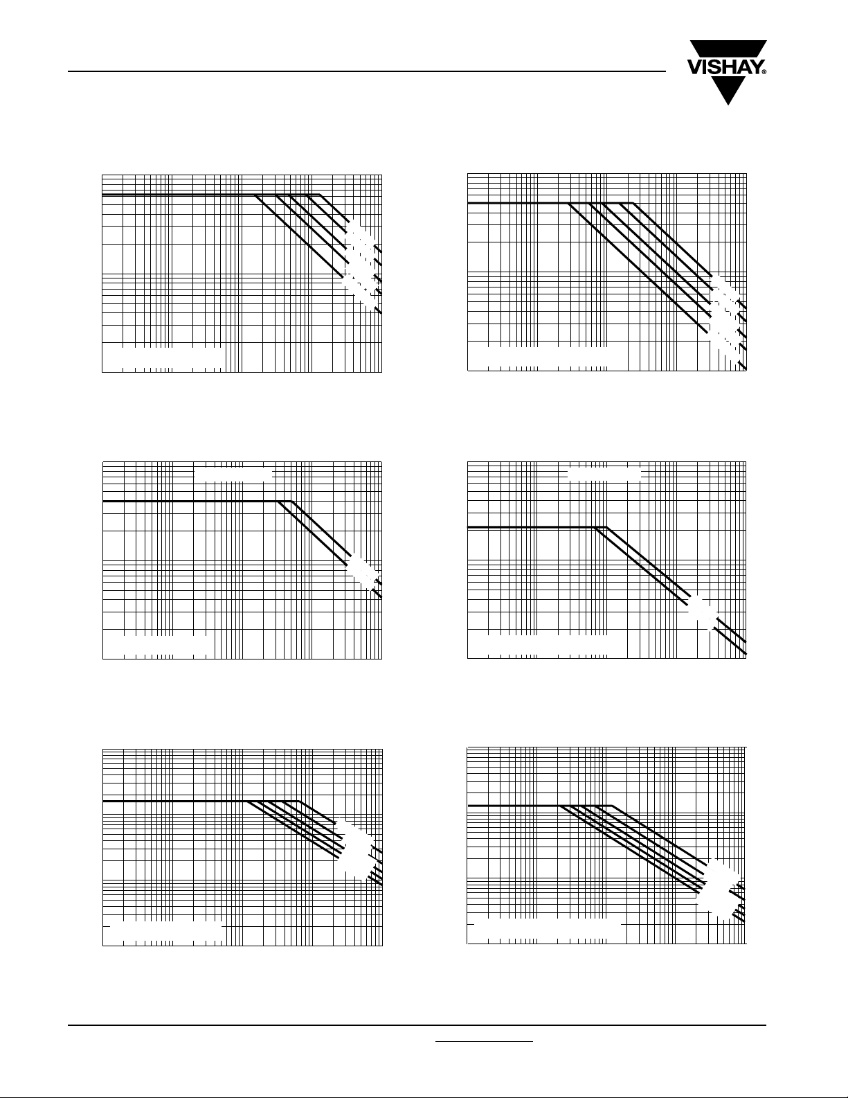
Capacitance as a function of frequency (typical curve) Capacitance as a function of temperature (typical curve)
2
C/C
(%)
1
0
- 1
- 2
- 3
2
10
Max. DC and AC voltage as a function of temperature Impedance as a function of frequency
1.2
DC Film Capacitor
Vishay BCcomponents
MKT Radial Potted Type
6
1 kHz
(%)
C/C
a. 63 V series
4
b. 100 V series
c. 250 V series
d. 400 V series
2
0
max.
typical
- 2
- 4
min.
- 6
T
3
10
4
10
f (Hz)
5
10
- 60
2
10
- 20 20 60 100
amb
(°C)
d
c
b
a
factor
1.0
0.8
0.6
0.4
0.2
0.0
- 60 - 20 20 60 100
T
(°C)
amb
Max. AC voltage as a function of frequency Max. AC voltage as a function of frequency
2
10
(V)
AC Voltage
56 nF
1
10
T
= 85 °C, 63 Vdc
amb
0
10
1
10
10
2
10
3
10
100 nF
220 nF
1000 nF
4
f (Hz)
5
10
63 V; 100 nF
10
250 V; 10 nF
6
7
f (Hz)
10
10
8
1
10
Impedance
(Ω)
0
10
- 1
10
- 2
10
- 3
10
4
10
2
10
63 V; 1 µF
(V)
AC Voltage
1
10
56 nF
100
22
nF
0 nF
1000 nF
T
≤ 105 °C, 63 Vdc
amb
0
5
10
10
1
10
10
2
10
3
10
4
f (Hz)
5
10
Document Number: 28108 For technical questions, contact: dc-film@vishay.com
www.vishay.com
Revision: 08-Dec-08 85
MKT 370
Vishay BCcomponents
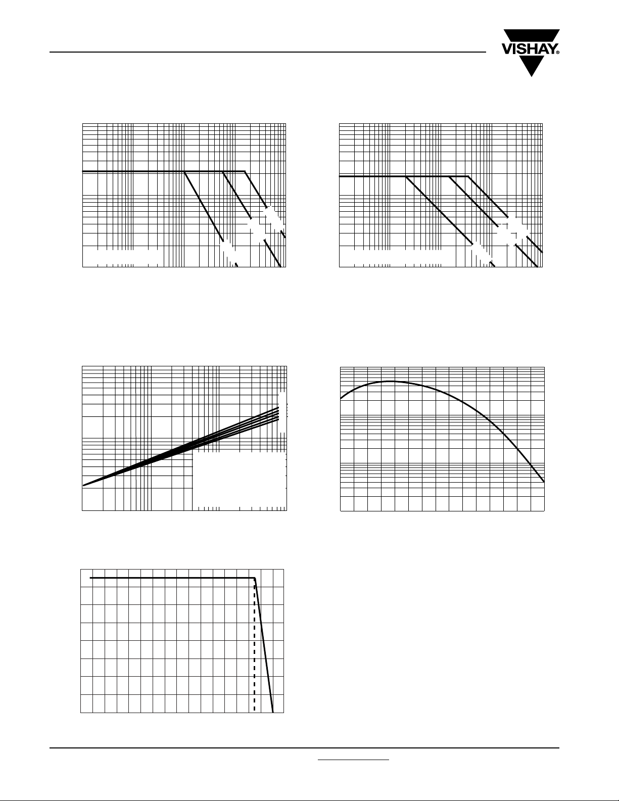
Max. AC voltage as a function of frequency Max. AC voltage as a function of frequency
2
10
(V)
AC Voltage
1
10
T
85 °C, 100 VDC
amb
0
10
1
10
10
2
Max. AC voltage as a function of frequency Max. AC voltage as a function of frequency
2
10
Compact size
10
3
DC Film Capacitor
MKT Radial Potted Type
12 nF
22 nF
47 nF
100 nF
330 nF
10
4
f (Hz)
5
10
2
10
(V)
AC Voltage
1
10
0
10
10
2
10
85 °C < T
1
≤ 105 °C, 100 VDC
amb
2
10
Compact size
10
12 nF
22 nF
47 nF
100 nF
330 nF
3
10
4
f (Hz)
5
10
AC Voltage
10
0
10
3
10
(V)
AC Voltage
2
10
1
10
(V)
(V)
AC Voltage
1
T
85 °C, 100 VDC
amb
1
10
10
100 nF
220 nF
10
3
10
4
f (Hz)
5
10
2
10
10
1
0
1
10
85 °C < T
≤ 105 °C, 100 VDC
amb
2
10
10
Max. AC voltage as a function of frequency Max. AC voltage as a function of frequency
3
10
(V)
AC Voltage
2
4.7 nF
10 nF
22 nF
47 nF
100 nF
10
1
10
100 nF
220 nF
3
10
4
f (Hz)
4.7 nF
10 nF
22 nF
47 nF
100 nF
5
10
T
≤ 85 °C, 250 VDC
amb
0
10
1
10
10
2
10
3
10
4
f (Hz)
5
10
85 °C < T
0
10
1
10
≤ 105 °C, 250 VDC
amb
2
10
10
3
10
4
f (Hz)
5
10
www.vishay.com For technical questions, contact: dc-film@vishay.com
Document Number: 28108
86 Revision: 08-Dec-08

MKT 370
2
10
(V)
AC Voltage
1
10
0
10
10
3
10
DC Film Capacitor
Vishay BCcomponents
MKT Radial Potted Type
Max. AC voltage as a function of frequency Max. AC voltage as a function of frequency
2
Compact size
10
(V)
AC Voltage
1
10
T
≤ 85 °C, 250 Vdc
amb
1
10
10
3
10
4
f (Hz)
5
10
2
10
0
1
10
85 °C < T
≤ 105 °C, 250 Vdc
amb
10
Max. AC voltage as a function of frequency Max. AC voltage as a function of frequency
3
10
2
Compact size
3
10
10
4
f (Hz)
5
10
AC Voltage
2
10
1
10
0
10
3
10
AC Voltage
2
10
1
10
(V)
(V)
AC Voltage
T
amb
1
10
≤ 85 °C, 400 Vdc
2
10
10
1.0 nF
2.2 nF
4.7 nF
10 nF
33 nF
3
10
4
f (Hz)
5
10
2
10
1
10
85 °C < T
0
10
1
10
≤ 105 °C, 400 Vdc
amb
2
10
10
Max. AC voltage as a function of frequency Max. AC voltage as a function of frequency
3
Compact size
10
(V)
(V)
AC Voltage
2
10
10 nF
22 nF
47 nF
100 nF
1
10
Compact size
1.0 nF
2.2 nF
4.7 nF
10 nF
33 nF
3
10
4
2.2 nF
4.7 nF
10 nF
f (Hz)
1.0 nF
5
10
T
≤ 85 °C, 400 Vdc
amb
0
10
1
10
10
2
10
3
10
4
f (Hz)
5
10
85 °C < T
0
10
1
10
≤ 105 °C, 400 Vdc
amb
2
10
10
3
10
4
f (Hz)
5
10
Document Number: 28108 For technical questions, contact: dc-film@vishay.com
www.vishay.com
Revision: 08-Dec-08 87
MKT 370
3
Vishay BCcomponents
DC Film Capacitor
MKT Radial Potted Type
Max. AC voltage as a function of frequency Max. AC voltage as fa unction of frequency
2
10
(V)
AC Voltage
1
10
0.68 nF
2.2 nF
33 nF
T
≤ 85 °C, 630 Vdc
amb
0
10
1
10
10
2
10
3
10
4
f (Hz)
5
10
Maximum RMS current (sinewave) as a function of frequency
The maximum RMS current is defined by Iac = ω x C x Uac.
Uac is the maximum AC voltage depending on the ambient temperature in the curves “Max. RMS voltage and AC current as a
function of frequency”.
Tangent of loss angle as a function of frequency
10
(typical curve)
2
10
(V)
AC Voltage
1
10
0.68 nF
2.2 nF
33 nF
10
0
10
85 °C < T
1
≤ 100 °C, 630 Vdc
amb
2
10
10
3
10
4
f (Hz)
Insulation resistance as a function of the ambient temperature
(typical curve)
5
10
5
10
)
-4
(x 10
Dissipation factor
2
10
Curve 1: C = 0.33 µF
5
4
3
2
1
10
10
RC (s)
4
3
Curve 2: 0.33 µF, C = 1.2 µF
Curve 3: 1.2 µF, C = 3.9 µF
Curve 4: 3.9 µF, C = 6.8 µF
1
10
2
10
3
10
Curve 5: C = 6.8 µF
4
10
f (Hz)
2
5
10
10
- 50 0
50
(°C)
100
T
amb
Maximum allowed component temperature rise (ΔT)
as a function of the ambient temperature (T
16
ΔT (°C)
12
8
4
amb
)
0
- 60 - 20 20 60 100
(°C)
T
amb
www.vishay.com For technical questions, contact: dc-film@vishay.com
Document Number: 28108
88 Revision: 08-Dec-08
MKT 370
DC Film Capacitor
Vishay BCcomponents
MKT Radial Potted Type
HEAT CONDUCTIVITY (G) AS A FUNCTION OF (ORIGINAL) PITCH AND CAPACITOR BODY THICKNESS IN mW/°C
W
max.
(mm)
2.5 2.5
3.5 3.0
4.5 4.0
6.0 5.5
POWER DISSIPATION AND MAXIMUM COMPONENT TEMPERATURE RISE
The power dissipation must be limited in order not to exceed the maximum allowed component temperature rise as a function of
the free ambient temperature.
The power dissipation can be calculated according type detail specification “HQN-384-01/101: Technical Information Film
Capacitors”.
The component temperature rise (ΔT) can be measured (see section “Measuring the component temperature” for more details)
or calculated by ΔT = P/G:
•ΔT = Component temperature rise (°C)
• P = Power dissipation of the component (mW)
• G = Heat conductivity of the component (mW/°C)
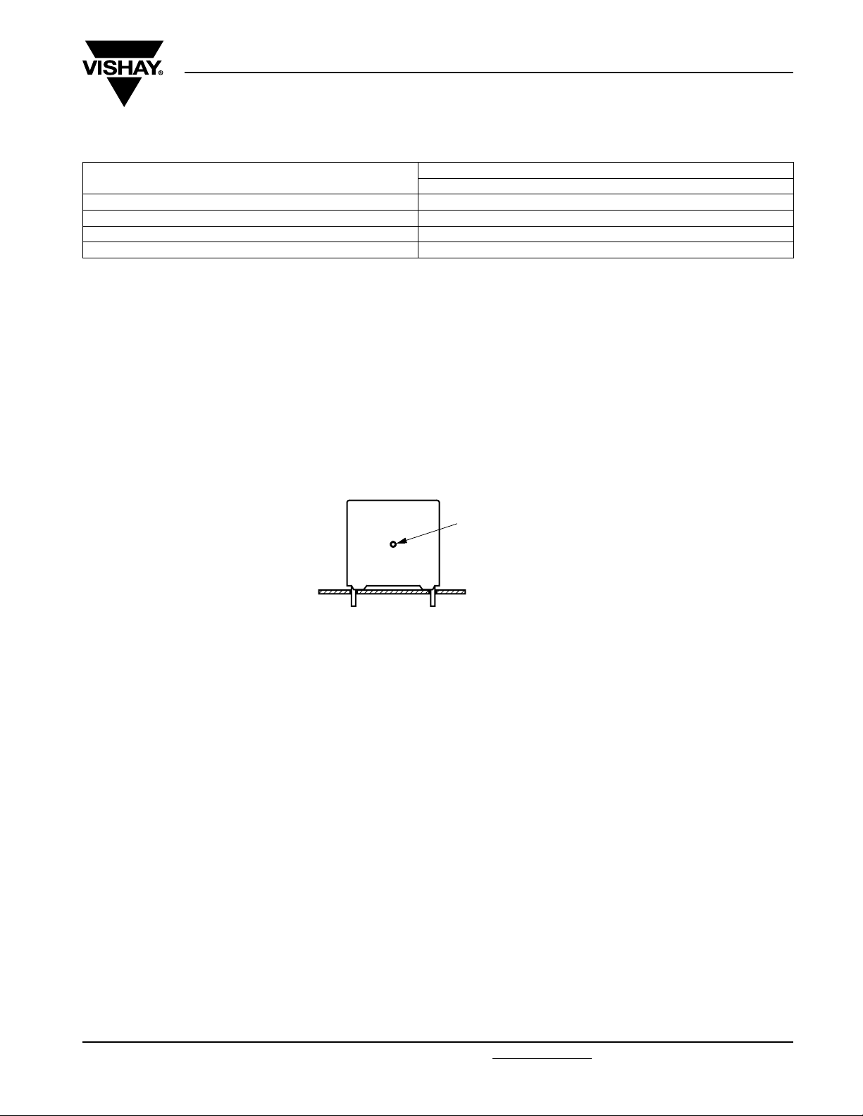
MEASURING THE COMPONENT TEMPERATURE
A thermocouple must be attached to the capacitor body as in:
HEAT CONDUCTIVITY (mW/°C)
PITCH 5 mm
Thermocouple
The temperature is measured in unloaded (T
The temperature rise is given by ΔT = T
C
) and maximum loaded condition (TC).
amb
- T
.
amb
To avoid radiation or convection, the capacitor should be tested in a wind-free box.
APPLICATION NOTE AND LIMITING CONDITIONS
These capacitors are not suitable for mains applications as across-the-line capacitors without additional protection, as described
hereunder. These mains applications are strictly regulated in safety standards and therefore electromagnetic interference
suppression capacitors conforming the standards must be used.
To select the capacitor for a certain application, the following conditions must be checked:
1. The peak voltage (U
2. The peak-to-peak voltage (U
) shall not be greater than the rated DC voltage (U
P
) shall not be greater than 2√2 x U
P-P
Rac
3. The voltage peak slope (dU/dt) shall not exceed the rated voltage pulse slope in an RC-circuit at rated voltage and without
ringing. If the pulse voltage is lower than the rated DC voltage, the rated voltage pulse slope may be multiplied by U
2 x
T
dU
⎛⎞
-------
∫
⎝⎠
dt
0
2
x dt U
divided by the applied voltage.
For all other pulses following equation must be fulfilled:
T is the pulse duration
.
4. The maximum component surface temperature rise must be lower than the limits (see figure max. allowed component
temperature rise).
5. Since in circuits used at voltages over 280 V peak-to-peak the risk for an intrinsically active flammability after a capacitor
breakdown (short circuit) increases, it is recommended that the power to the component is limited to 100 times the values
mentioned in the table: “Heat conductivity”
6. When using these capacitors as across-the-line capacitor in the input filter for mains applications or as series connected with
an impedance to the mains the applicant must guarantee that the following conditions are fulfilled in any case (spikes and
surge voltages from the mains included).
Document Number: 28108 For technical questions, contact: dc-film@vishay.com
Revision: 08-Dec-08 89
)
Rdc
to avoid the ionisation inception level
dU
⎛⎞
-------
x
<
Rdc
⎝⎠
dt
rated
and
Rdc
www.vishay.com

MKT 370
Vishay BCcomponents
DC Film Capacitor
MKT Radial Potted Type
Voltage Conditions for 6 Above
≤ 85 °C 85 °C < T
ALLOWED VOLTAGES
Maximum continuous RMS voltage U
Maximum temperature RMS-overvoltage (< 24 h) 1.25 x U
Maximum peak voltage (V
O-P
) (< 2 s)
EXAMPLE
C = 330 nF - 63 V used for the voltage signal shown in next drawing.
U
= 40 V; UP = 35 V; T1 = 100 µs; T2 = 200 µs
P-P
The ambient temperature is 35 °C
Checking conditions:
1. The peak voltage U
2. The peak-to-peak voltage 40 V is lower than 2√2 x 40 Vac = 113 U
3. The voltage pulse slope (dU/dt) = 40 V/100 µs = 0.4 V/µs
This is lower than 60 V/µs (see specific reference data for each version)
4. The dissipated power is 16.2 mW as calculated with fourier terms
The temperature rise for W
This is lower than 15 °C temperature rise at 35 °C, according figure max. allowed component temperature rise
5. Not applicable
6. Not applicable
= 35 V is lower than 63 Vdc
P
= 3.5 mm and pitch = 5 mm will be 16.2 mW/3.0 mW/°C = 5.4 °C
max.
T
amb
1.6 x U
P-P
Rac
See “Max. AC voltage as function
of temperature CBB952” per
characteristics
Rac
Rdc
amb
U
Rac
1.3 x U
≤ 100 °C
Rdc
Voltage Signal
Voltage
U
P
U
P-P
T
1
T
2
www.vishay.com For technical questions, contact: dc-film@vishay.com
90 Revision: 08-Dec-08
Time
Document Number: 28108

MKT 370
DC Film Capacitor
Vishay BCcomponents
MKT Radial Potted Type
INSPECTION REQUIREMENTS
General Notes:
Sub-clause numbers of tests and performance requirements refer to the “Sectional Specification, Publication IEC 60384-2 and
Specific Reference Data”.
Group C Inspection Requirements
SUB-CLAUSE NUMBER AND TEST CONDITIONS PERFORMANCE REQUIREMENTS
SUB-GROUP C1A PART OF SAMPLE
OF SUB-GROUP C1
4.1 Dimensions (detail) As specified in chapters “MKT 370 General
Data” of this specification
4.3.1 Initial measurements Capacitance
4.3 Robustness of terminations Tensile and bending No visible damage
4.4 Resistance to soldering heat Method: 1A
4.14 Component solvent resistance Isopropylalcohol at room temperature
4.4.2 Final measurements Visual examination No visible damage
SUB-GROUP C1B PART OF SAMPLE
OF SUB-GROUP C1
4.6.1 Initial measurements Capacitance
4.6 Rapid change of temperature θA = - 55 °C
4.7 Vibration Visual examination
4.7.2 Final inspection Visual examination No visible damage
Document Number: 28108 For technical questions, contact: dc-film@vishay.com
Revision: 08-Dec-08 91
Tangent of loss angle:
For C ≤ 470 nF at 100 kHz or
for C > 470 nF at 10 kHz
Solder bath: 280 °C ± 5 °C
Duration: 10 s
Method: 2
Immersion time: 5 ± 0.5 min
Recovery time: Min. 1 h, max. 2 h
Legible marking
Capacitance |ΔC/C| ≤ 2 % of the value measured initially
Tangent of loss angle Increase of tan δ
≤ 0.005 for:
C ≤ 100 nF or
≤ 0.010 for:
100 nF < C ≤ 220 nF or
≤ 0.015 for:
220 nF < C ≤ 470 nF and
≤ 0.003 for:
C > 470 nF
Compared to values measured in 4.3.1
Tangent of loss angle:
For C ≤ 470 nF at 100 kHz or
for C > 470 nF at 10 kHz
θB = + 100 °C
5 cycles
Duration t = 30 min
No visible damage
Mounting:
See section “Mounting” of this specification
Procedure B4
Frequency range: 10 Hz to 55 Hz
Amplitude: 0.75 mm or
Acceleration 98 m/s²
(whichever is less severe)
Total duration 6 h
www.vishay.com

MKT 370
Vishay BCcomponents
DC Film Capacitor
MKT Radial Potted Type
SUB-CLAUSE NUMBER AND TEST CONDITIONS PERFORMANCE REQUIREMENTS
4.9 Shock Mounting:
See section “Mounting” of this specification
Pulse shape: Half sine
Acceleration: 490 m/s²
Duration of pulse: 11 ms
4.9.3 Final measurements Visual examination No visible damage
Capacitance |ΔC/C| ≤ 3 % of the value measured in 4.6.1
Tangent of loss angle Increase of tan δ
≤ 0.010 for:
C ≤ 220 nF or
≤ 0.015 for:
220 nF < C ≤ 470 nF and
≤ 0.003 for:
C > 470 nF
Compared to values measured in 4.6.1
Insulation resistance As specified in section “Specific Reference
Data 370” of this specification
SUB-GROUP C1 COMBINED SAMPLE
OF SPECIMENS OF SUB-GROUPS
C1A AND C1B
4.10 Climatic sequence
4.10.2 Dry heat Temperature: + 100 °C
Duration: 16 h
4.10.3 Damp heat cyclic
Test Db, first cycle
4.10.4 Cold Temperature: - 55 °C
Duration: 2 h
4.10.6 Damp heat cyclic
Test Db, remaining cycles
4.10.6.2 Final measurements Voltage proof = U
after removal from testchamber
Visual examination No visible damage
Capacitance |ΔC/C| ≤ 5 % of the value measured in
Tangent of loss angle Increase of tan δ
Insulation resistance ≥ 50 % of values specified in section “Specific
SUB-GROUP C2
4.11 Damp heat steady state 56 days, 40 °C, 90 % to 95 % RH
4.11.1 Initial measurements Capacitance
Tangent of loss angle at 1 kHz
for 1 min within 15 min
Rdc
No breakdown of flash-over
Legible marking
4.4.2 or 4.9.3
≤ 0.010 for:
C ≤ 220 nF or
≤ 0.015 for:
220 nF < C ≤ 470 nF and
≤ 0.005 for:
C > 470 nF
Compared to values measured in
4.3.1 or 4.6.1
Reference Data 370” of this specification
www.vishay.com For technical questions, contact: dc-film@vishay.com
92 Revision: 08-Dec-08
Document Number: 28108

MKT 370
DC Film Capacitor
Vishay BCcomponents
MKT Radial Potted Type
SUB-CLAUSE NUMBER AND TEST CONDITIONS PERFORMANCE REQUIREMENTS
4.11.3 Final measurements Voltage proof = U
SUB-GROUP C3
4.12 Endurance Duration: 2000 h
4.12.1 Initial measurements Capacitance
4.12.5 Final measurements Visual examination No visible damage
SUB-GROUP C4
4.13 Charge and discharge 10 000 cycles
4.13.1 Initial measurements Capacitance
4.13.3 Final measurements Capacitance |ΔC/C| ≤ 3 % compared to values measured
after removal from testchamber
Visual examination No visible damage
Capacitance |ΔC/C| ≤ 5 % of the value measured in 4.11.1.
Tangent of loss angle Increase of tan δ ≤ 0.005
Insulation resistance ≥ 50 % of values specified in section “Specific
1.25 x U
0.8 x 1.25 U
Tangent of loss angle:
For C ≤ 470 nF at 100 kHz or
for C > 470 nF at 10 kHz
Capacitance |ΔC/C| ≤ 5 % compared to values measured
Tangent of loss angle Increase of tan δ
Insulation resistance ≥ 50 % of values specified in section “Specific
Charged to U
Discharge resistance:
Tangent of loss angle:
For C ≤ 470 nF at 100 kHz or
for C > 470 nF at 10 kHz
Tangent of loss angle Increase of tan δ
Insulation resistance ≥ 50 % of values specified in section “Specific
R
Rdc
=
at 85 °C
Rdc
for 1 min within 15 min
Rdc
at 100 °C
Rdc
U
-------------------------------------------------C 2.5 dU dt⁄()
R
××
R
No breakdown of flash-over
Legible marking
Compared to values measured in 4.11.1
Reference Data 370” of this specification
Legible marking
in 4.12.1
≤ 0.005 for at 85 °C
≤ 0.010 for at 100 °C for:
C ≤ 220 nF or
≤ 0.015 for:
220 nF < C ≤ 470 nF and
≤ 0.003 for:
C > 470 nF
Compared to values measured in 4.12.1
Reference Data 370” of this specification
in 4.13.1
≤ 0.005 for:
C ≤ 100 nF or
≤ 0.010 for:
100 nF < C ≤ 220 nF or
≤ 0.015 for:
220 nF < C ≤ 470 nF and
≤ 0.003 for:
C > 470 nF
Compared to values measured in 4.13.1
Reference Data 370” of this specification
Document Number: 28108 For technical questions, contact: dc-film@vishay.com
Revision: 08-Dec-08 93
www.vishay.com

Legal Disclaimer Notice
Vishay
Disclaimer
All product specifications and data are subject to change without notice.
Vishay Intertechnology, Inc., its affiliates, agents, and employees, and all persons acting on its or their behalf
(collectively, “Vishay”), disclaim any and all liability for any errors, inaccuracies or incompleteness contained herein
or in any other disclosure relating to any product.
Vishay disclaims any and all liability arising out of the use or application of any product described herein or of any
information provided herein to the maximum extent permitted by law. The product specifications do not expand or
otherwise modify Vishay’s terms and conditions of purchase, including but not limited to the warranty expressed
therein, which apply to these products.
No license, express or implied, by estoppel or otherwise, to any intellectual property rights is granted by this
document or by any conduct of Vishay.
The products shown herein are not designed for use in medical, life-saving, or life-sustaining applications unless
otherwise expressly indicated. Customers using or selling Vishay products not expressly indicated for use in such
applications do so entirely at their own risk and agree to fully indemnify Vishay for any damages arising or resulting
from such use or sale. Please contact authorized Vishay personnel to obtain written terms and conditions regarding
products designed for such applications.
Product names and markings noted herein may be trademarks of their respective owners.
Document Number: 91000 www.vishay.com
Revision: 18-Jul-08 1
 Loading...