

Page 1
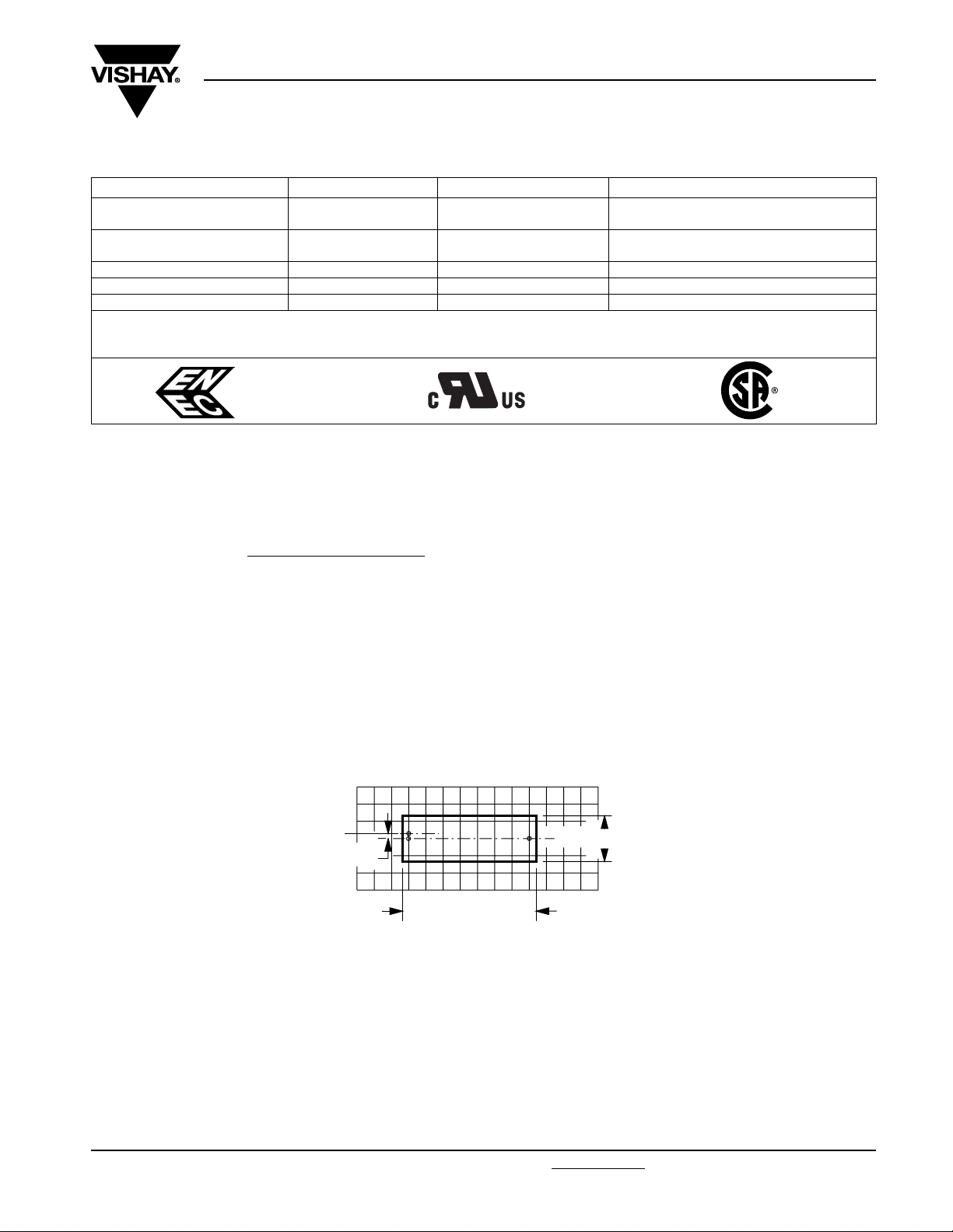
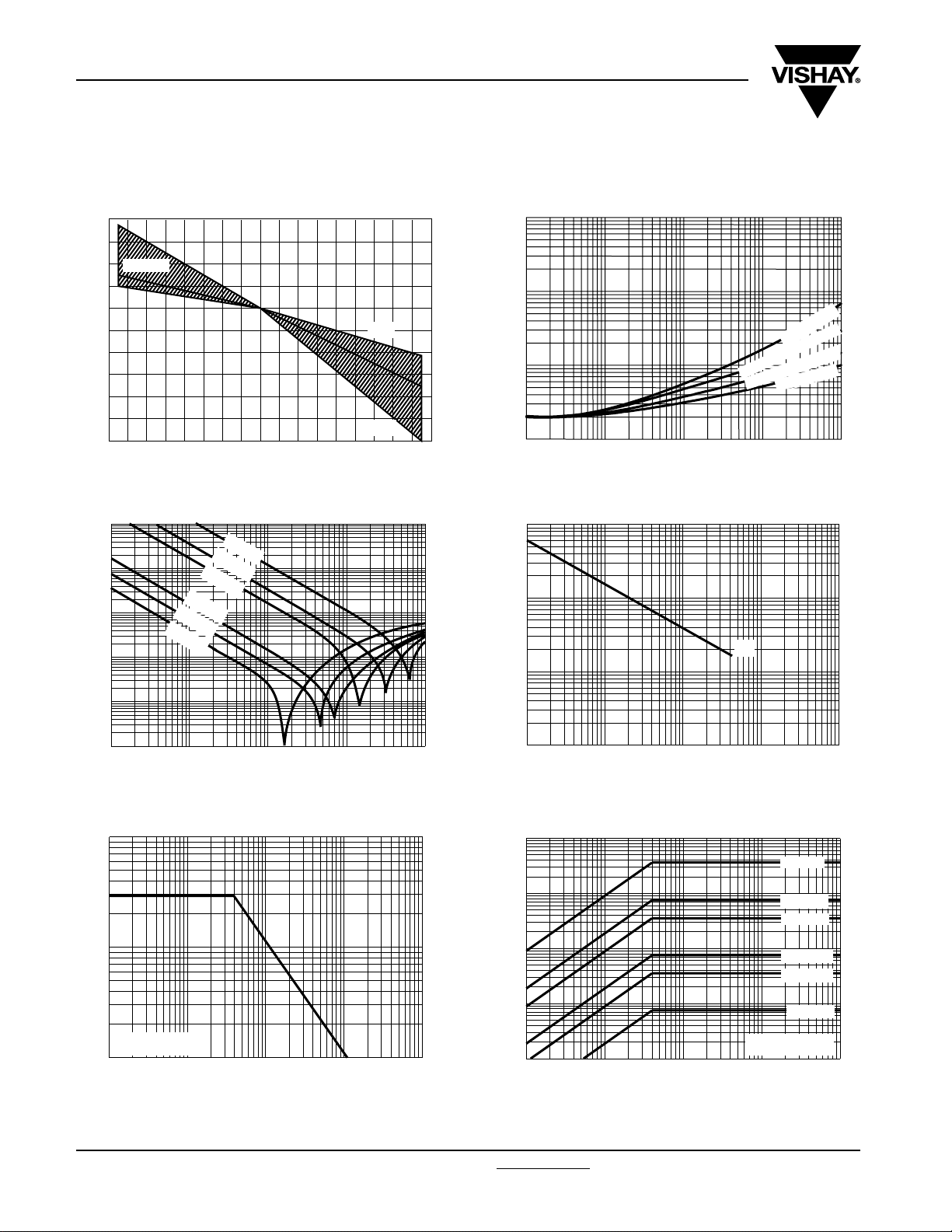
MKP 338 6 Y2
168x12(halfpage)
Vishay BCcomponents
Interference Suppression Film Capacitors
MKP Radial Potted Type
l
168x12(halfpage)
h
l
t
P
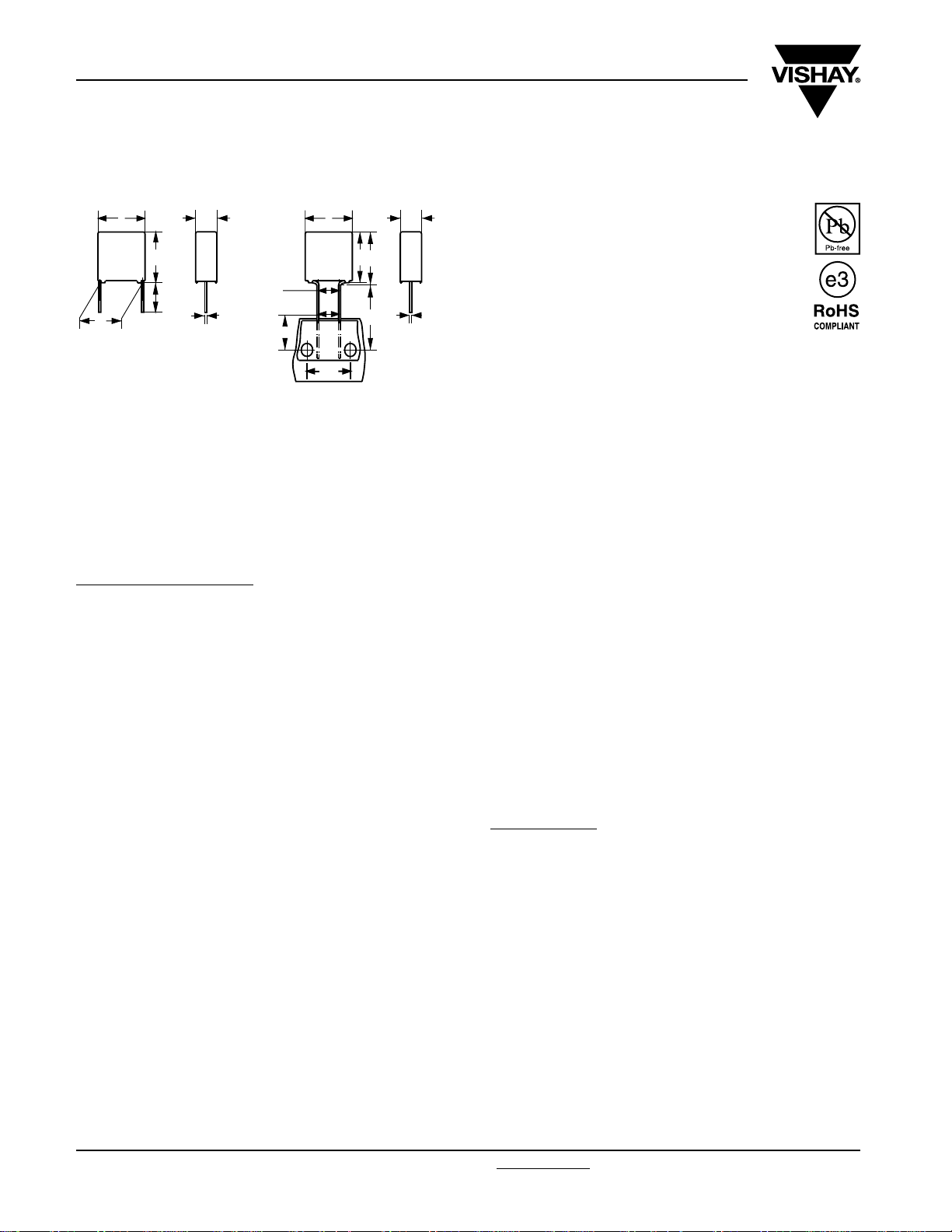
Dimensions in mm
Note
(1)
|F - F’| < 0.3 mm
F = 7.5 + 0.6/- 0.1 mm
w
F'
¯d
F
t
10
(1)
15
l
h
w
h'
H
¯d
APPLICATIONS
For standard line bypass (between line and ground) Y2
applications
See also application note:
www.vishay.com/doc?28153
REFERENCE STANDARDS
“IEC 60384-14 ed-3 and EN 60384-14”
“IEC 60065 requires, pass. flamm. class B”
UL1414; CSA - C22.2 No. 1;
UL1283; ENEC; CSA E 384-14-95
FEATURES
7.5 to 27.5 mm lead pitch, 15 mm and 10 mm bent
back to 7.5 mm, supplied loose in box, taped on
ammopack or reel
RoHS compliant product
t
PERMISSIBLE DC VOLTAGE
DC 1000 V
ENCAPSULATION
Plastic case, epoxy resin sealed, flame retardant UL-class
94 V-0
CLIMATIC TESTING CLASS ACC. TO IEC 60068-1
55/105/56/B
CAPACITANCE RANGE (E12 SERIES)
E12 series 0.001 to 0.47 µF
Preferred values acc. to E6
CAPACITANCE TOLERANCE
± 20 %; ± 10 %; ± 5 %
LEADS
Tinned wire
MARKING
C-value; tolerance; rated voltage; sub-class; manufacturer’s
MAXIMUM APPLICATION TEMPERATURE
105 °C
type designation; code for dielectric material, manufacturer
location; manufacturer’s logo, year and week; safety
approvals
DIELECTRIC
DETAIL SPECIFICATION
For more detailed data and test requirements contact:
RFI@vishay.com
Polypropylene film
ELECTRODES
Metallized film
CONSTRUCTION
Series and triple construction
RATED VOLTAGE
AC 300 V; 50 to 60 Hz
www.vishay.com For technical questions, contact: RFI@vishay.com
364 Revision: 23-Jan-09
Document Number: 28114
Page 2
MKP 338 6 Y2
Interference Suppression Film Capacitors
Vishay BCcomponents
MKP Radial Potted Type
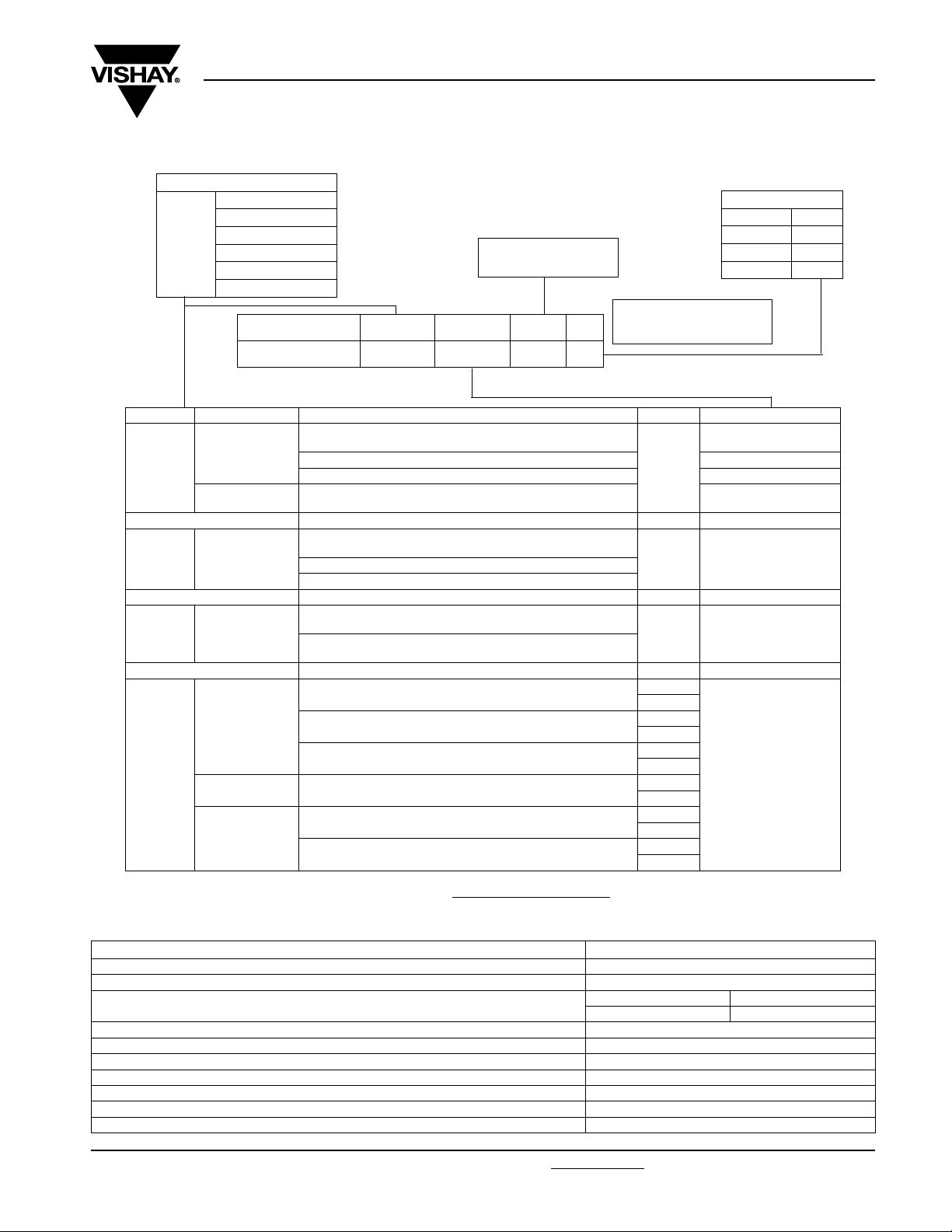
COMPOSITION OF CATALOG NUMBER
TYPE AND PITCHES
7.5 mm
338 6
TYPE PACKAGING STANDARD DIMENSIONS C-TOL PREFERRED TYPES
338 6
Y2
338 6
Y2
338 6
Y2
338 6
Y2
Note
(1)
For detailed tape specification refer to “Packaging Information” www.vishay.com/doc?28139 or end of catalog
7.5 mm (bent back)
Y2
Loose in box
Taped ammo
Loose in box
Taped reel
Loose in box
Taped ammo
Taped reel
10.0 mm
15.0 mm
22.5 mm
27.5 mm
CAPACITANCE
(numerically)
BFC2 338 6X XX X
2222
(*) old ordering code
(1)
(1)
(*)
Lead length 3.5 + 1/- 0.5 mm (pitch 7.5 and 10 mm)
Lead length 3.5 ± 0.3 mm (pitch > 10 mm)
Lead length 5.0 ± 1.0 mm BFC2 338 62
Lead length 25.0 ± 2.0 mm BFC2 338 64
Pitch = 7.5 mm
H = 18.5 mm; P
Lead length 3.5 + 1/- 0.5 mm (pitch 7.5 and 10 mm)
Lead length 3.5 ± 0.3 mm (pitch > 10 mm)
Lead length 5.0 ± 1.0 mm
Lead length 25.0 ± 2.0 mm
Pitch = 7.5 and 10.0 mm
H = 18.5 mm; for P0= 12.7 mm; reel diameter = 500 mm
Pitch bent back to 7.5 mm
H = 16.0 mm; P
Lead length 3.5 + 1/- 0.5 mm (pitch 7.5 and 10 mm) ± 10 %
Lead length 3.5 ± 0.3 mm (pitch > 10 mm) ± 5 %
Lead length 5.0 ± 1.0 mm
Lead length 25.0 ± 2.0 mm
Pitch=7.5mm
(1)
H = 18.5 mm; for P
Pitch bent back to 7.5 mm
H = 16.0 mm; P
Pitch = 7.5 mmand 10.0 mm
H = 18.5 mm; P
338 6X XX X
= 12.7 mm
0
ALTERNATIVE PITCH SIZES ON REQUEST
ALTERNATIVE TAPED VERSION ON REQUEST
= 15.0 mm; reel diameter = 500 mm
0
ALTERNATIVE C-TOL ON REQUEST
= 12.7 mm
0
= 15.0 mm; reel diameter = 500 mm
0
= 12.7 mm; reel diameter = 500 mm
0
Example:
104 = 10 x 10 = 100 nF
(except special numbers)
± 20 %
± 20 % See tables for details
± 20 % See tables for details
± 10 %
± 5 %
± 10 %
± 5 %
± 10 %
± 5 %
± 10 %
± 5 %
± 10 %
± 5 %
MULTIPLIER (nF)
0.1 2
13
10 4
100 5
BFC2 338 60
BFC2 338 66
See tables for details
SPECIFIC REFERENCE DATA
DESCRIPTION VALUE
Rated AC voltage (U
Permissible DC voltage (U
Tangent of loss angle
C ≤ 470 nF ≤ 10 x 10
Rated voltage pulse slope (dU/dt)R at 420 Vdc 100 V/µs
R between leads, for C ≤ 0.33 µF at 100 V; 1 min > 15 000 MΩ
RC between leads, for C > 0.33 µF at 100 V; 1 min > 5000 s
R between leads and case; 100 V; 1 min > 30 000 MΩ
Withstanding (DC) voltage (cut off current 10 mA); max. rise time 100 V/s 3400 V; 1 min
Withstanding (AC) voltage between leads and case 2100 V; 1 min
Maximum application temperature 105 °C
Document Number: 28114 For technical questions, contact: RFI@vishay.com
Revision: 23-Jan-09 365
) 300 V
Rac
) 1000 V
Rdc
at 1 kHz at 10 kHz
-4
≤ 20 x 10
-4
www.vishay.com
Page 3
MKP 338 6 Y2
Vishay BCcomponents
Interference Suppression Film Capacitors
MKP Radial Potted Type
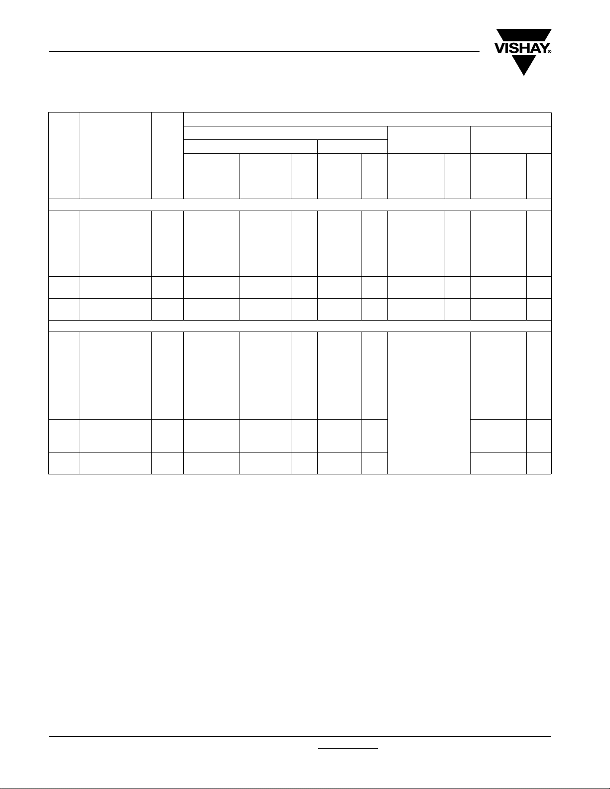
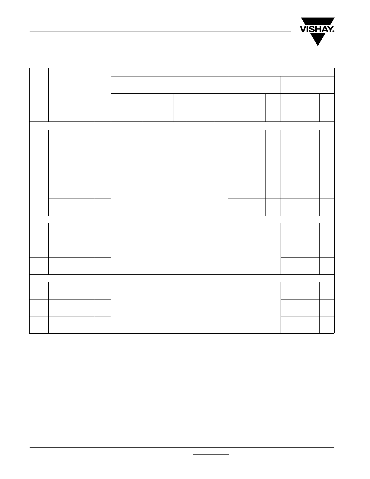
U
= 300 V; C-tol = ± 20 % (U
Rac
C
(µF)
Pitch = 7.5 ± 0.4 mm; d
0.001
0.0012 60122 62122 64122 66122 68131
0.0015 60152 62152 64152 66152 68132
0.0018 60182 62182 64182 66182 68133
0.0022 60222 62222 64222 66222 68134
0.0027 60272 62272 64272 66272 68135
0.0033
0.0039 60392 62392 64392 66392 68137
0.0047
0.0056 60562 62562 64562 66562 68139
Pitch = 10.0 ± 0.4 mm; d
0.001
0.0012 68393 68402 68411 68419
0.0015 68394 68403 68412 68421
0.0018 68395 68404 68413 68422
0.0022 68396 68405 68414 68423
0.0027 68397 68406 68415 68424
0.0033 68398 68407 68416 68425
0.0039 68399 68408 68417 68426
0.0047
0.0068 68103 68108 68114 68143
0.0082
0.01 68105 68111 68116 68145
Note
(1)
Weight for short lead product only
• SPQ = Standard Packing Quantity
DIMENSIONS
w x h x l
(mm)
= 0.50 ± 0.05 mm
t
4.0 x 9.0 x 10.0 0.4
5.0 x 10.5 x 10.0 0.4
6.0 x 11.5 v 10.0 0.8
4.0 x 10.0 x 12.5 0.6
5.0 x 11.0 x 12.5 0.82
6.0 x 12.0 x 12.5 1.1
= 1000 V)
Rdc
MASS
(1)
(g)
+ 1/- 0.5 mm
= 0.60 ± 0.06 mm
t
CATALOG NUMBER BFC2 338 6X XXX AND PACKAGING
LOOSE IN BOX
Short leads Long leads
l
= 3.5
t
60102 62102
60332 62332
60472 62472
68392 68401
68101 68106
68104 68109
lt= 5.0
± 1.0 mm
SPQ
1500
1000
750
1000
1000
750
lt= 25.0
± 2.0 mm
64102
64332
64472
68409
68112
68115
SPQ
1000
1250
1000
1250
1000
750
AMMOPACK REEL
H = 18.5 mm;
P
= 12.7 mm
0
66102
66332
66472
SPQ
1250
1000
750
REEL:
Ø = 500 mm
H = 18.5 mm;
P
= 12.7 mm
0
68129
68136
68138
68418
68141
68144
SPQ
2500
2000
1900
1400
11000.0056 68102 68107 68113 68142
900
www.vishay.com For technical questions, contact: RFI@vishay.com
366 Revision: 23-Jan-09
Document Number: 28114
Page 4
MKP 338 6 Y2
Interference Suppression Film Capacitors
Vishay BCcomponents
MKP Radial Potted Type
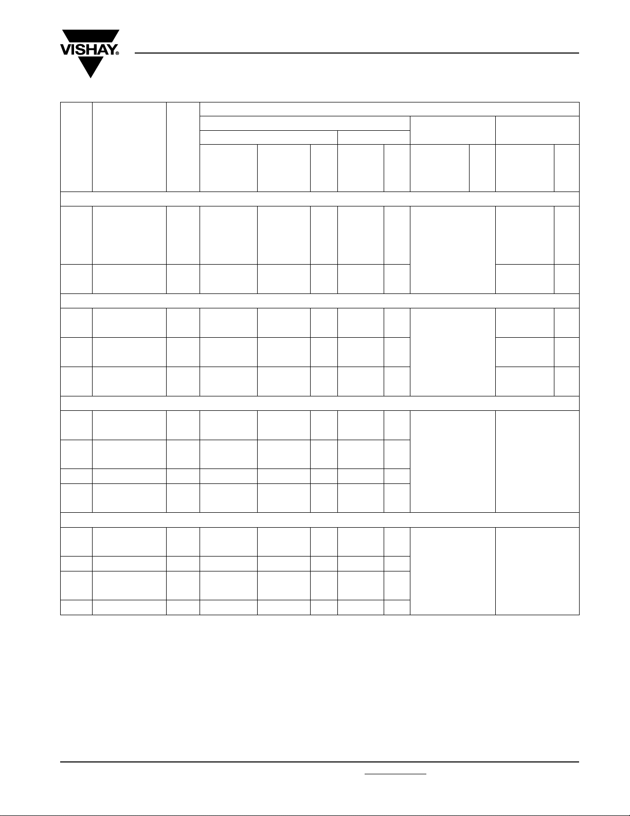
CATALOG NUMBER BFC2 338 6X XXX AND PACKAGING
LOOSE IN BOX
C
(µF)
Pitch = 15.0 ± 0.4 mm; d
0.0068
0.0082 60822 62822 64822 68147
0.01 60103 62103 64103 68148
0.012 60123 62123 64123 68149
0.015
0.018 60183 62183 64183 68152
Pitch = 15.0 ± 0.4 mm; d
0.022
0.027 60273 62273 64273 68154
0.033
0.039 60393 62393 64393 68156
0.047
0.056 60563 62563 64563 68158
Pitch = 22.5 ± 0.4 mm; d
0.047
0.056 68124 68126 68128
0.068
0.082 60823 62823 64823
0.1 10.0 x 19.5 x 26.0 6.8 60104 62104 200 64104 200
0.12
0.15 60154 62154 64154
Pitch = 27.5 ± 0.4 mm; d
0.18
0.22 60224 62224 64224
0.27 15.0 x 25.0 x 31.0 12.3 60274 62274 100 64274 125
0.33
0.39 60394 62394 64394
0.47 21.0 x 31.0 x 31.0 20.3 60474 62474 50 64474 75
DIMENSIONS
w xhxl
(mm)
5.0 x 11.0 x 17.5 1.0
6.0 x 12.0 x 17.5 1.4
7.0 x 13.5 x 17.5 1.8
8.5 x 15.0 x 17.5 2.4
10.0 x 16.5 x 17.5 3.0
7.0 x 16.5 x 26.0 2.9
8.5 x 18.0 x 26.0 3.8
12.0 x 22.0 x 26.0 7.8
13.0 x 23.0 x 31.0 9.2
18.0 x 28.0 x 31.0 16.1
MASS
(1)
(g)
+ 1/- 0.5 mm
= 0.60 ± 0.06 mm
t
= 0.80 ± 0.08 mm
t
= 0.80 ± 0.08 mm
t
= 0.80 ± 0.08 mm
t
l
Short leads Long leads
= 3.5
t
60682 62682
60153 62153
60223 62223
60333 62333
60473 62473
68123 68125
60683 62683
60124 62124
60184 62184
60334 62334
lt= 5.0
± 1.0 mm
SPQ
1000
1000
750
750
500
200
200
150
100
100
lt= 25.0
± 2.0 mm
64682
64153
64223
64333
64473
68127
64683
64124
64184
64334
SPQ
1000
1000
500
500
450
250
250
200
125
100
AMMOPACK REEL
H=18.5mm;
P
= 12.7 mm
0
SPQ
REEL:
Ø = 500 mm
H = 18.5 mm;
P
= 12.7 mm
0
68146
68151
68153
68155
68157
SPQ
1100
900
800
650
600
Note
(1)
Weight for short lead product only
• SPQ = Standard Packing Quantity
Document Number: 28114 For technical questions, contact: RFI@vishay.com
Revision: 23-Jan-09 367
www.vishay.com
Page 5
MKP 338 6 Y2
Vishay BCcomponents
Interference Suppression Film Capacitors
MKP Radial Potted Type
Bent back pitch 7.5 mm
CATALOG NUMBER BFC2 338 6X XXX AND PACKAGING
LOOSE IN BOX
C
(µF)
Original pitch = 10.0 mm; bent back pitch = 7.5 ± 0.4 mm; d
0.001
0.0012 68526 68428
0.0015 68527 68429
0.0018 68528 68431
0.0022 68529 68432
0.0027 68531 68433
0.0033 68532 68434
0.0039 68533 68435
0.0047
0.0056 68535 68118
Original pitch = 15.0 mm; bent back pitch = 7.5 ± 0.4 mm; d
0.0068
0.0082
0.01
0.012
0.015
0.018
Original pitch = 15.0 mm; bent back pitch = 7.5 ± 0.4 mm; d
0.022
0.027
DIMENSIONS
w x h x l
(mm)
4.0 x 12.0 x 12.5 0.6
5.0 x 13.0 x 12.5 0.82
5.0 x 13.0 x 17.5 1.1
6.0 x 14.0 x 17.5 1.4
7.0 x 15.5 x 17.5 1.8
MASS
(1)
(g)
+ 1/- 0.5 mm
Short leads Long leads
l
= 3.5
t
lt= 5.0
± 1.0 mm
SPQ
= 0.60 ± 0.06 mm
t
= 0.60 ± 0.06 mm
t
= 0.80 ± 0.08 mm
t
lt= 25.0
± 2.0 mm
SPQ
AMMOPACK REEL
H=16mm;
P
=15mm
0
68525
68534
SPQ
1300
1000
REEL:
Ø = 500 mm
H = 16 mm;
P
=15mm
0
68427
68117
66682
66822
66103
66123
66153
66183
66223
66273
SPQ
2000
1900
950
800
700
0.033
0.039
0.047
0.056
Notes
(1)
Reel diameter = 356 mm is available on request
(2)
Weight for short lead product only
• SPQ = Standard Packing Quantity
www.vishay.com For technical questions, contact: RFI@vishay.com
368 Revision: 23-Jan-09
8.5 x 17.0 x 17.5 2.4
10.0 x 18.5 x 17.5 3.0
66333
66393
66473
66563
Document Number: 28114
550
500
Page 6
MKP 338 6 Y2
Interference Suppression Film Capacitors
Vishay BCcomponents
MKP Radial Potted Type
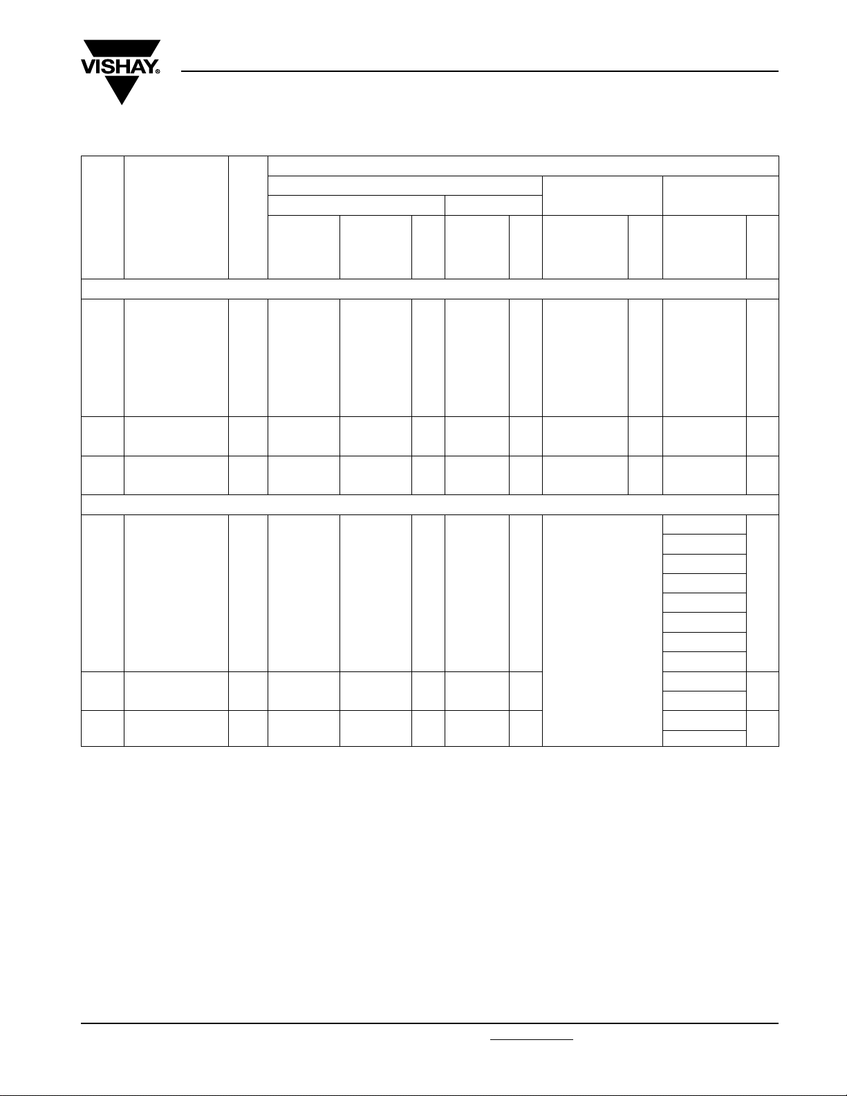
U
300 V; C-Tol = 10 % (U
Rac =
C
(µF)
Pitch = 7.5 ± 0.4 mm; d
0.001
0.0012 61122 63122 65122
0.0015 61152 63152 65152
0.0018 61182 63182 65182
0.0022 61222 63222 65222
0.0027 61272 63272 65272
0.0033
0.0039 61392 63392 65392
0.0047
0.0056 65562
Pitch = 10.0 ± 0.4 mm; d
0.001
0.0012 68437 68446 68455 68464
0.0015 68438 68447 68456 68465
0.0018 68439 68448 68457 68466
0.0022 68441 68449 68458 68467
0.0027 68442 68451 68459 68468
0.0033 68443 68452 68461 68469
0.0039 68444 68453 68462 68471
0.0047
0.0056 68161 68165 68169 68193
0.0068
0.0082 68163 68167 68172 68194
Note
(1)
Weight for short lead product only
• SPQ = Standard Packing Quantity
DIMENSIONS
w x h x l
(mm)
4.0 x 9.0 x 10.0 0.4
5.0 x 10.5 x 10.0 0.4
6.0 x 11.5 x 10.0 0.8
4.0 x 10.0 x 12.5 0.6
5.0 x 11.0 x 12.5 0.82
6.0 x 12.0 x 12.5 1.1
= 1000 V)
Rdc
MASS
(1)
(g)
+ 1/- 0.5 mm
= 0.50 ± 0.05 mm
t
= 0.60 ± 0.06 mm
t
CATALOG NUMBER BFC2 338 6X XXX AND PACKAGING
LOOSE IN BOX
Short leads Long leads
l
= 3.5
t
61102 63102
61332 63332
61472
61562
68436 68445
68159 68164
68162 68166
lt= 5.0
± 1.0 mm
63472
63562
SPQ
1500
1000
750
1000
1000
750
lt= 25.0
± 2.0 mm
65102
65332
65472
68454
68168
68171
SPQ
1000
1250
1000
1250
1000
750
AMMOPACK REEL
H=18.5mm;
P
= 12.7 mm
0
67102
67122
67152
67182
67222
67272
67332
67392
67472
67562
SPQ
1250
1000
750
Ø = 500 mm
H = 18.5 mm;
P
= 12.7 mm
0
REEL:
68179
68181
68182
68183
68184
68185
68186
68187
68188
68189
68463
68191
68193
SPQ
2500
2000
1900
1400
1100
900
Document Number: 28114 For technical questions, contact: RFI@vishay.com
Revision: 23-Jan-09 369
www.vishay.com
Page 7

MKP 338 6 Y2
Vishay BCcomponents
Interference Suppression Film Capacitors
MKP Radial Potted Type
CATALOG NUMBER BFC2 338 6X XXX AND PACKAGING
LOOSE IN BOX
C
(µF)
Pitch = 15.0 ± 0.4 mm; d
0.0068
0.0082 61822 63822 65822 68203
0.01 61103 63103 65103 68204
0.012 61123 63123 65123 68205
0.015
0.018 61183 63183 65183 68207
Pitch = 15.0 ± 0.4 mm; d
0.022 7.0 x 13.5 x 17.5 1.8 61223 63223
0.027
0.033 61333 63333 65333 68211
0.039
0.047 61473 63473 65473 68213
Pitch = 22.5 ± 0.4 mm; d
0.047 7.0 x 16.5 x 26.0 2.9 68173 68175
0.068 61683 63683 65683
0.082
0.1 61104 63104 65104
0.12
0.15 61154 63154 65154
Pitch = 27.5 ± 0.4 mm; d
0.18 13.0 x 23.0 x 31.0 9.2 61184 63184
0.22 15.0 x 25.0 x 31.0 12.3 61224 63224 65224
0.27
0.33 61334 63334 65334
0.39
0.47 61474 63474 65474
DIMENSIONS
w x h x l
(mm)
5.0 x 11.0 x 17.5 1
6.0 x 12.0 x 17.5 1.4
8.5 x 15.0 x 17.5 2.4
10.0 x 16.5 x 17.5 3
8.5 x 18.0 x 26.0 3.8
10.0 x 19.5 x 26.0 6.8
12.0 x 22.0 x 26.0 7.8
18.0 x 28.0 x 31.0 16.1
21.0 x 31.0 x 31.0 20.3
MASS
(1)
(g)
+ 1/- 0.5 mm
= 0.60 ± 0.06 mm
t
= 0.80 ± 0.08 mm
t
= 0.80 ± 0.08 mm
t
= 0.80 ± 0.08 mm
t
l
Short leads Long leads
= 3.5
t
61682 63682
61153 63153 65153 68206
61273 63273 65273 68209
61393 63393
68174 68176 68178
61823 63823 65823
61124 63124
61274 63274 65274
61394 63394
lt= 5.0
± 1.0 mm
SPQ
1000
750
500
200
150
100
50
lt= 25.0
± 2.0 mm
65682
65223
65393
68177
65124
65184
65394
SPQ
1000
500
450
2500.056
200
200
125
100
75
AMMOPACK REEL
H=18.5mm;
P
= 12.7 mm
0
SPQ
REEL:
Ø = 500 mm
H = 18.5 mm;
P
= 12.7 mm
0
68202
68208 800
68212
SPQ
1100
900
650
600
Note
(1)
Weight for short lead product only
• SPQ = Standard Packing Quantity
www.vishay.com For technical questions, contact: RFI@vishay.com
370 Revision: 23-Jan-09
Document Number: 28114
Page 8
MKP 338 6 Y2
Interference Suppression Film Capacitors
Vishay BCcomponents
MKP Radial Potted Type
Bent back pitch 7.5 mm
CATALOG NUMBER BFC2 338 6X XXX AND PACKAGING
LOOSE IN BOX
C
(µF)
Original pitch = 10.0 mm; bent back pitch = 7.5 ± 0.4 mm; d
0.001
0.0012 68541 68473
0.0015 68542 68474
0.0018 68543 68475
0.0022 68544 68476
0.0027 68545 68477
0.0033 68546 68478
0.0039 68547 68479
0.0047
0.0056 68549 68197
Original pitch = 15.0 mm; bent back pitch = 7.5 ± 0.4 mm; d
0.0068
0.0082 67822
0.01 67103
0.012
0.015
0.018 67183
Original pitch = 15.0 mm; bent back pitch = 7.5 ± 0.4 mm; d
0.022 7.0 x 15.5 x 17.5 1.8
0.027
0.033 67333
0.039
0.047
DIMENSIONS
w x h x l
(mm)
4.0 x 12.0 x 12.5 0.6
5.0 x 13.0 x 12.5 1.1
5.0 x 13.0 x 17.5 1.0
6.0 x 14.0 x 17.5 1.4
8.5 x 17.0 x 17.5 2.4
10.0 x 18.5 x 17.5 3.0
MASS
(1)
(g)
+ 1/- 0.5 mm
Short leads Long leads
l
= 3.5
t
lt= 5.0
± 1.0 mm
= 0.60 ± 0.06 mm
t
= 0.60 ± 0.06 mm
t
= 0.80 ± 0.08 mm
t
SPQ
lt= 25.0
± 2.0 mm
SPQ
AMMOPACK REEL
H=16mm;
P
=15mm
0
68539
68548
SPQ
1300
1000
REEL:
Ø = 500 mm
H = 16 mm;
P
=15mm
0
68472
68196
67682
67123
67153
67223 700
67273
67393
67473
SPQ
2000
1900
950
800
550
500
Notes
(1)
Reel diameter = 356 mm is available on request
(2)
Weight for short lead product only
• SPQ = Standard Packing Quantity
Document Number: 28114 For technical questions, contact: RFI@vishay.com
Revision: 23-Jan-09 371
www.vishay.com
Page 9

MKP 338 6 Y2
Vishay BCcomponents
Interference Suppression Film Capacitors
MKP Radial Potted Type
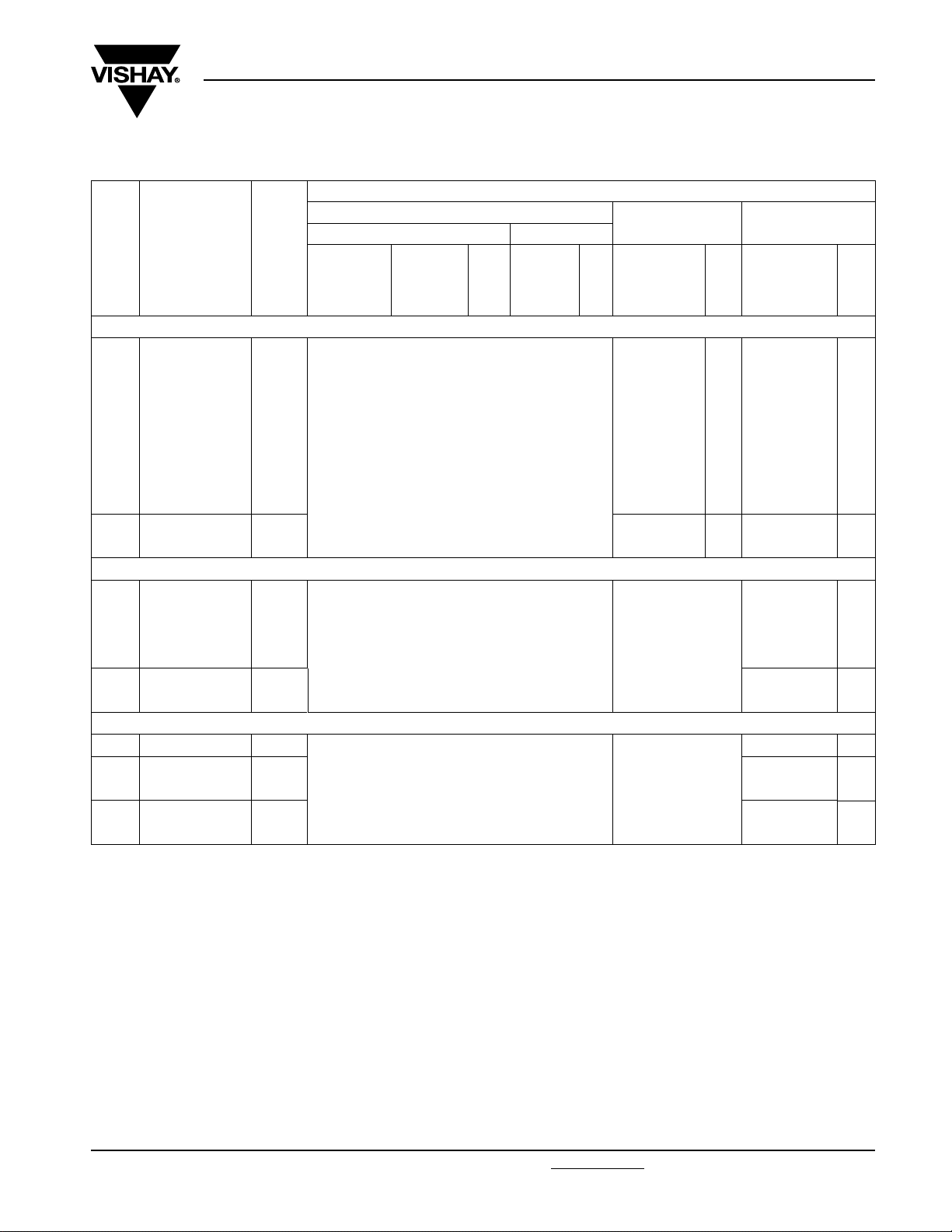
U
= 300 V; C-tol = 5 % (U
Rac
C
(µF)
Pitch = 7.5 ± 0.4 mm; d
0.001
0.0012 68216 68226 68236 68336 68347
0.0015 68217 68227 68237 68337 68348
0.0018 68218 68228 68238 68338 68349
0.0022 68219 68229 68239 68339 68351
0.0027
0.0033 68222 68232 68242 68342 68353
0.0039
0.0047 68224 68234 68244 68344 68355
Pitch = 10.0 ± 0.4 mm; d
0.001
0.0012 68482 68491 68499 68508
0.0015 68483 68492 68501 68509
0.0018 68484 68493 68502 68511
0.0022 68485 68494 68503 68512
0.0027 68486 68495 68504 68513
0.0033 68487 68496 68505 68514
0.0039 68488 68497 68506 68515
0.0047
0.0056 68246 68251 68255 68358
0.0068
0.0082 68248 68253 68257 68361
Note
(1)
Weight for short lead product only
• SPQ = Standard Packing Quantity
DIMENSIONS
w x h x l
(mm)
4.0 x 9.0 x 10.0 0.4
5.0 x 10.5 x 10.0 0.4
6.0 x 11.5 x 10.0 0.8
4.0 x 10.0 x 12.5 0.6
5.0 x 11.0 x 12.5 0.82
6.0 x 12.0 x 12.5 1.1
= 1000 V)
Rdc
MASS
(1)
(g)
= 0.50 ± 0.05 mm
t
= 0.60 ± 0.06 mm
t
l
0.5 mm
68215 68225
68221 68231
68223 68233
68481 68489
68245 68249
68247 68252
CATALOG NUMBER BFC2 338 6X XXX AND PACKAGING
LOOSE IN BOX
Short leads Long leads
= 3.5
t
+ 1/-
l
= 5.0
t
± 1.0 mm
SPQ
1500
1000
750
1000
1000
750
lt= 25.0
± 2.0 mm
68235
68241
68243
68498
68254
68256
SPQ
1000
1250
1000
1250
1000
750
AMMOPACK REEL
H = 18.5 mm;
P
= 12.7 mm
0
68335
68341
68343
SPQ
1250
1000
750
REEL:
Ø = 500 mm
H = 18.5 mm;
P
= 12.7 mm
0
68346
68352
68354
68507
68357
68359
SPQ
2500
2000
1900
1400
1100
900
www.vishay.com For technical questions, contact: RFI@vishay.com
372 Revision: 23-Jan-09
Document Number: 28114
Page 10
MKP 338 6 Y2
Interference Suppression Film Capacitors
Vishay BCcomponents
MKP Radial Potted Type
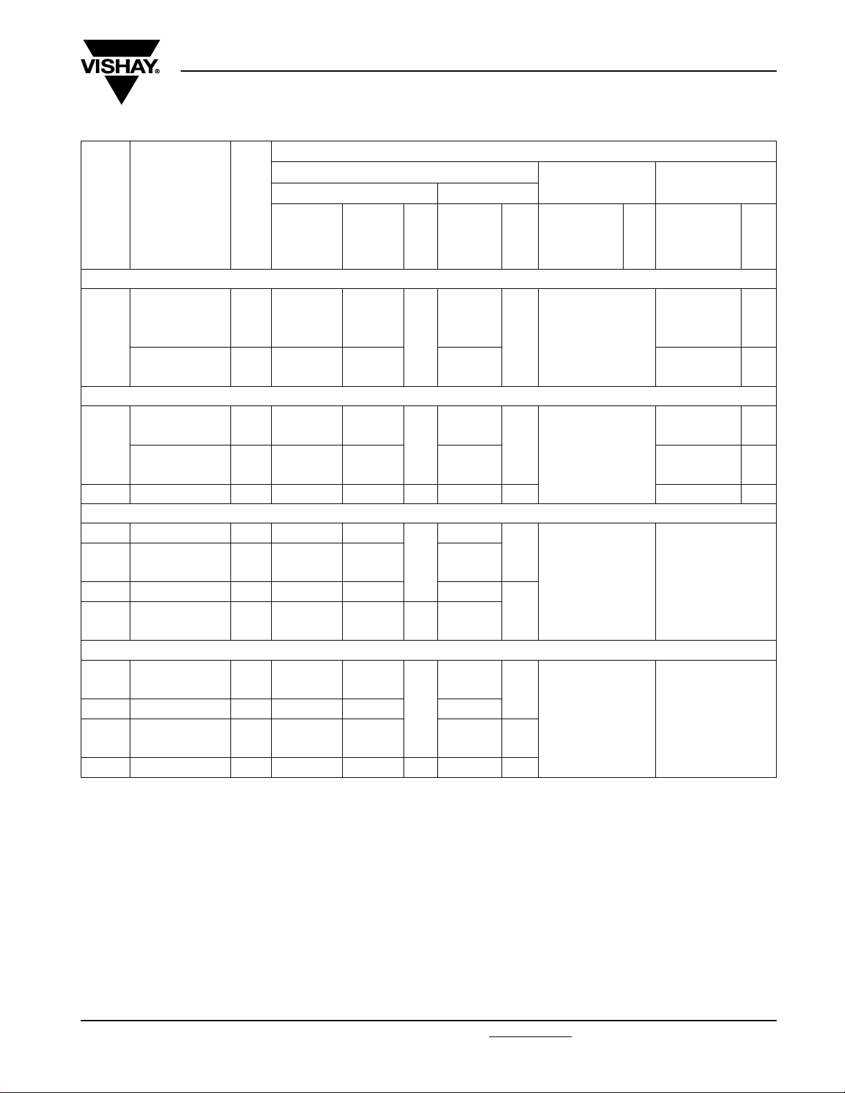
CATALOG NUMBER BFC2 338 6X XXX AND PACKAGING
LOOSE IN BOX
C
(µF)
Pitch = 15.0 ± 0.4 mm; d
0.0068
0.01 68261 68286 68312 68383
0.012
0.015 68263 68288 68314 68385
Pitch = 15.0 ± 0.4 mm; d
0.018
0.022 68265 68291 68316 68387
0.027
0.033 68267 68293 68318 68389
0.039 10.0 x 16.5 x 17.5 3.0 68268 68294 500 68319 450 68391 600
Pitch = 22.5 ± 0.4 mm; d
0.047 7.0 x 16.5 x 26.0 2.9 68269 68295
0.068 68272 68297 68323
0.082 10.0 x 19.5 x 26.0 6.8 68273 68298 68324
0.12 68275 68301 68326
Pitch = 27.5 ± 0.4 mm; d
0.15
0.22 15.0 x 25.0 x 31.0 12.3 68278 68304 68329
0.27
0.33 68281 68306 68332
0.39 21.0 x 31.0 x 31.0 20.3 68282 68307 50 68333 75
Notes
(1)
Weight for short lead product only
• SPQ = Standard Packing Quantity
DIMENSIONS
w x h x l
(mm)
5.0 x 11.0 x 17.5 1.0
6.0 x 12.0 x 17.5 1.4
7.0 x 13.5 x 17.5 1.8
8.5 x 15.0 x 17.5 2.4
8.5 x 18.0 x 26.0 3.8
12.0 x 22.0 x 26.0 7.8
13.0 x 23.0 x 31.0 9.2
18.0 x 28.0 x 31.0 16.1
MASS
(1)
(g)
+ 1/- 0.5 mm
= 0.60 ± 0.06 mm
t
= 0.80 ± 0.08 mm
t
= 0.80 ± 0.08 mm
t
= 0.80 ± 0.08 mm
t
Short leads Long leads
= 3.5
l
t
68258 68284
68262 68287 68313 68384
68264 68289
68266 68292 68317 68388
68271 68296 68322
68274 68299
68276 68302
68279 68305 68331 100
lt= 5.0
± 1.0 mm
SPQ
1000
750
200
150
100
lt= 25.0
± 2.0 mm
68309
68315
68321
68325
68327
SPQ
1000
500
2500.056
2000.1
1250.18 68277 68303 68328
AMMOPACK REEL
H=18.5mm;
P
= 12.7 mm
0
SPQ
REEL:
Ø = 500 mm
H = 18.5 mm;
P
= 12.7 mm
0
68381
68386
SPQ
11000.0082 68259 68285 68311 68382
900
800
650
Document Number: 28114 For technical questions, contact: RFI@vishay.com
Revision: 23-Jan-09 373
www.vishay.com
Page 11

MKP 338 6 Y2
Vishay BCcomponents
Interference Suppression Film Capacitors
MKP Radial Potted Type
Bent back pitch = 7.5 mm
CATALOG NUMBER BFC2 338 6X XXX AND PACKAGING
LOOSE IN BOX
C
(µF)
Original pitch = 10.0 mm; bent back pitch = 7.5 ± 0.4 mm; d
0.001
0.0012 68554 68517
0.0015 68555 68518
0.0018 68556 68519
0.0022 68557 68521
0.0027 68558 68522
0.0033 68559 68523
0.0039 68561 68524
0.0047
0.0056 68563 68364
Original pitch = 15.0 mm; bent back pitch = 7.5 ± 0.4 mm; d
0.0068
0.01 68371
0.012
0.015 68373
Original pitch = 15.0 mm; bent back pitch = 7.5 ± 0.4 mm; d
0.018
0.022 68375
0.027
0.033 68377
0.039 10.0 x 18.5 x 17.5 3 68378 500
Notes
(1)
Reel diameter = 356 mm is available on request
(2)
Weight for short lead product only
• SPQ = Standard Packing Quantity
DIMENSIONS
w x h x l
(mm)
4.0 x 12.0 x 12.5 0.6
5.0 x 13.0 x 12.5 0.82
5.0 x 13.0 x 17.5 1.1
6.0 x 14.0 x 17.5 1.4
7.0 x 15.5 x 17.5 1.8
8.5 x 17.0 x 17.5 2.4
MASS
(1)
(g)
+ 1/- 0.5 mm
Short leads Long leads
l
t
= 3.5
lt= 5.0
± 1.0 mm
SPQ
= 0.60 ± 0.06 mm
t
= 0.60 ± 0.06 mm
t
= 0.80 ± 0.08 mm
t
lt= 25.0
± 2.0 mm
SPQ
AMMOPACK REEL
H=16mm;
P
=15mm
0
68553
68562
SPQ
1300
1000
REEL:
Ø = 500 mm
H = 16 mm;
P
= 15 mm
0
68516
68363
68368
68372
68374
68376
SPQ
2000
1900
9500.0082 68369
800
700
550
www.vishay.com For technical questions, contact: RFI@vishay.com
374 Revision: 23-Jan-09
Document Number: 28114
Page 12
MKP 338 6 Y2
6
Interference Suppression Film Capacitors
Vishay BCcomponents
MKP Radial Potted Type
APPROVALS
SAFETY APPROVALS Y2 VOLTAGE VALUE FILE NUMBERS
EN 60384-14 (ENEC)
(= IEC 60384-14 ed-3)
UL1414 and CSA-C22.2 No 1
antenna coupling
UL1283 300 Vac 1 nF to 470 nF E109565
CSA-E384-14-95 300 Vac 1 nF to 470 nF 1377022
CB-Test Certificate 300 Vac 1 nF to 470 nF FI 5265
The Enec-approval together with the CB-Certificate replace all national marks of the following countries (they have already signed the
ENEC-Agreement): Austria; Belgium; Czech. Republic; Denmark; Finland; France; Germany; Greece; Hungary; Ireland; Italy; Luxembourg;
Netherlands; Norway; Portugal; Slovenian; Spain; Switzerland and United Kingdom.
300 Vac 1 nF to 470 nF FI 2008062
250 Vac 1 nF to 470 nF E112471
®
16
MOUNTING
Normal Use
The capacitors are designed for mounting on printed-circuit boards. The capacitors packed in bandoliers are designed for
mounting in printed-circuit boards by means of automatic insertion machines.
For detailed tape specifications refer to
“Packaging Information”: www.vishay.com/doc?28139
Specific Method of Mounting to Withstand Vibration and Shock
In order to withstand vibration and shock tests, it must be ensured that the stand-off pips are in good contact with the
printed-circuit board:
• For pitches ≤ 15 mm capacitors shall be mechanically fixed by the leads
• For longer pitches the capacitors shall be mounted in the same way and the body clamped
Space Requirements on Printed Circuit-Board
The maximum length and width of film capacitors is shown in drawing:
• Eccentricity as in drawing. The maximum eccentricity is smaller than or equal to the lead diameter of the product concerned
• Product height with seating plane as given by “IEC 60717” as reference: h
or end of catalog
≤ h + 0.3 mm or
max.
h
≤ h’ + 0.3 mm
max.
b
= b + 0.3 mm
max.
Eccentricity
l
= I + 0.3 mm
max.
CBA11
Storage Temperature
• Storage temperature: T
= - 25 °C to + 40 °C with RH maximum 80 % without condensation
stg
Ratings and Characteristics Reference Conditions
Unless otherwise specified, all electrical values apply to an ambient temperature of 23 °C ± 1 °C, an atmospheric pressure of
86 to 106 kPa and a relative humidity of 50 % ± 2 %.
For reference testing, a conditioning period shall be applied over 96 h ± 4 h by heating the products in a circulating air oven at
the rated temperature and a relative humidity not exceeding 20 %.
Document Number: 28114 For technical questions, contact: RFI@vishay.com
Revision: 23-Jan-09 375
www.vishay.com
Page 13
MKP 338 6 Y2
Vishay BCcomponents
Interference Suppression Film Capacitors
CHARACTERISTICS
Capacitance as a function of ambient temperature
(typical curve)
4
ΔC/C
(%)
2
typical
0
- 2
- 4
- 6
- 50
Impedance as a function of frequency (typical curve)
3
10
2
10
1
Impedance
(Ω)
10
0
10
-1
10
470 nF
050
1 nF
4.7 nF
10 nF
47 nF
100 nF
MKP Radial Potted Type
Tangent of loss angle as a function of frequency (typical curve)
3
10
)
-4
Dissipation
factor (x 10
2
10
max.
1
10
min.
100
(°C)
T
amb
0
10
10
Resonant frequency as a function of capacitance (typical curve)
2
10
f (MHz)
1
10
0
10
C > 220 nF
C ≤ 10 n
f (Hz)
F
5
10
47 nF < C ≤ 220 nF
10 nF < C ≤ 47 nF
1
2
10
3
10
4
10
Y2
-2
10
4
10
5
10
6
10
7
f (Hz)
10
8
10
Max. RMS voltage as a function of frequency
3
10
-1
10
1 10 100 1000
Max. RMS current as a function of frequency
3
10
C (nF)
10 000
470 nF
2
10
AC current
AC voltage
(V)
2
10
(mA)
1
10
100 nF
47 nF
10 nF
4.7 nF
0
10
10
10
T
≤ 105 °C
amb
1
1
10
2
10
3
4
10
f (Hz)
5
10
10
10
-1
1
10
2
10
3
10
T
amb
4
1nF
≤ 105 °C
f (Hz)
5
10
www.vishay.com For technical questions, contact: RFI@vishay.com
Document Number: 28114
376 Revision: 23-Jan-09
Page 14

MKP 338 6 Y2
Interference Suppression Film Capacitors
Vishay BCcomponents
MKP Radial Potted Type
Insulation resistance as a function of ambient temperature
6
10
RC (s)
5
10
4
10
0
20 40 60
APPLICATION NOTES
• For Y2 electromagnetic interference suppression in, standard line bypass applications (between line and ground)
(50/60 Hz) with a maximum mains voltage of 300 Vac
• For series impedance applications we refer to Application Note www.vishay.com/doc?28153
• These capacitors are not intended for continuous pulse applications. For these situations, capacitors of the AC and pulse
programs must be used.
• The maximum ambient temperature must not exceed 105 °C
• Rated voltage pulse slope:
If the pulse voltage is lower than the rated voltage, the values of the specific reference data can be multiplied by 420 Vdc and
divided by the applied voltage.
80
T
100
amb
(°C)
Document Number: 28114 For technical questions, contact: RFI@vishay.com
Revision: 23-Jan-09 377
www.vishay.com
Page 15

MKP 338 6 Y2
Vishay BCcomponents
Interference Suppression Film Capacitors
MKP Radial Potted Type
INSPECTION REQUIREMENTS
General Notes:
1. Sub-clause numbers of tests and performance requirements refer to the “Sectional Specification, Publication
IEC 60384-14 ed-3 and Specific Reference Data.
Group C Inspection Requirements
SUB-CLAUSE NUMBER
AND TEST
SUB-GROUP C1A PART OF SAMPLE OF
SUB-GROUP C1
4.1 Dimensions (detail) As specified in Chapters “General data” of
Initial measurements Capacitance
CONDITIONS PERFORMANCE REQUIREMENTS
this specification
Tangent of loss angle:
at 10 kHz
4.3 Robustness of
terminations
4.4 Resistance to soldering heat No pre-drying
4.19 Component solvent
resistance
4.4.2 Final measurements Visual examination No visible damage
Tensile: load 10 N; 10 s
Bending: load 5 N; 4 x 90°
Method: 1A
Solder bath: 280 °C ± 5 °C
Duration: 10 s
Isopropylalcohol at room temperature
Method: 2
Immersion time: 5 ± 0.5 min
Recovery time:
Min. 1 h, max. 2 h
Capacitance |ΔC/C| ≤ 5 % of the value measured initially
Tangent of loss angle Increase of tan δ ≤ 0.008
Insulation resistance As specified in Section “Insulation
No visible damage
Legible marking
Compared to values measured initially
Resistance” of this specification
www.vishay.com For technical questions, contact: RFI@vishay.com
378 Revision: 23-Jan-09
Document Number: 28114
Page 16

MKP 338 6 Y2
Interference Suppression Film Capacitors
MKP Radial Potted Type
SUB-CLAUSE NUMBER
AND TEST
SUB-GROUP C1B PART OF SAMPLE OF
SUB-GROUP C1
Initial measurements Capacitance
4.20 Solvent resistance of the marking: Isopropylalcohol at room temperature
4.6 Rapid change of temperature θA = - 55 °C
4.6.1 Inspection
4.7 Vibration
CONDITIONS PERFORMANCE REQUIREMENTS
Tangent of loss angle:
at 10 kHz
Method: 1
Rubbing material: cotton wool
Immersion time: 5 ± 0.5 min
θB = + 105 °C
5 cycles
Duration t = 30 min
Visual examination
Mounting: see Section “Mounting” of this
specification
Procedure B4:
Frequency range: 10 to 55 Hz
Amplitude: 0.75 mm or
Acceleration 98 m/s²
(whichever is less severe)
Total duration 6 h
Vishay BCcomponents
No visible damage
Legible marking
No visible damage
4.7.2 Final inspection Visual examination No visible damage
4.9 Shock Mounting: see Section “Mounting” for more
information
Pulse shape: half sine
Acceleration: 490 m/s²
Duration of pulse: 11 ms
4.9.2 Final measurements Visual examination No visible damage
Capacitance |ΔC/C| ≤ 5 % of the value measured initially
Tangent of loss angle Increase of tan δ ≤ 0.008
Insulation resistance As specified in Section “Insulation
Compared to values measured initially
Resistance” of this specification
Document Number: 28114 For technical questions, contact: RFI@vishay.com
Revision: 23-Jan-09 379
www.vishay.com
Page 17

MKP 338 6 Y2
Vishay BCcomponents
Interference Suppression Film Capacitors
MKP Radial Potted Type
SUB-CLAUSE NUMBER
AND TEST
SUB-GROUP C1 COMBINED SAMPLE
OF SPECIMENS OF SUB-GROUPS C1A
AND C1B
4.11 Climatic sequence
4.11.1 Initial measurements Capacitance
4.11.2 Dry heat Temperature: 105 °C
4.11.3 Damp heat cyclic
Tes t D b
First cycle
4.11.4 Cold Temperature: - 55 °C
4.11.5 Damp heat cyclic
Tes t D b
remaining cycles
4.11.6 Final measurements Visual examination No visible damage
SUB-GROUP C2
4.12 Damp heat steady state 56 days, 40 °C, 90 to 95 % RH, no load
4.12.1 Initial measurements Tangent of loss angle at 1 kHz
4.12.3 Final measurements Visual examination No visible damage
CONDITIONS PERFORMANCE REQUIREMENTS
Measured in 4.4.2 and 4.9.2
Tangent of loss angle:
Measured initially in C1A and C1B
Duration: 16 h
Duration: 2 h
Legible marking
Capacitance |ΔC/C| ≤ 5 % of the value measured in
Tangent of loss angle Increase of tan δ ≤ 0.008
Voltage proof
2250 Vdc; 1 min between terminations
Insulation resistance ≥ 50 % of values specified in Section
Capacitance
Capacitance |ΔC/C| ≤ 5 % of the value measured in
Tangent of loss angle Increase of tan δ ≤ 0.007
Voltage proof
2250 Vdc; 1 min between terminations
Insulation resistance ≥ 50 % of values specified in Section
4.11.1.
Compared to values measured in 4.11.1
No permanent breakdown or flash-over
“Insulation resistance” of this specification
Legible marking
4.12.1.
Compared to values measured in
4.12.1.
No permanent breakdown or flash-over
“Insulation resistance” of this specification
www.vishay.com For technical questions, contact: RFI@vishay.com
380 Revision: 23-Jan-09
Document Number: 28114
Page 18

MKP 338 6 Y2
Interference Suppression Film Capacitors
Vishay BCcomponents
MKP Radial Potted Type
SUB-CLAUSE NUMBER
AND TEST
SUB-GROUP C3
4.13.1 Initial measurements Capacitance
4.13 Impulse voltage 3 successive impulses, full wave, peak
4.14 Endurance Duration: 1000 h
4.14.7 Final measurements Visual examination No visible damage
CONDITIONS PERFORMANCE REQUIREMENTS
Tangent of loss angle:
at 10 kHz
No selfhealing breakdowns or flash-over
voltage:
X1: 5 kV
Max. 24 pulses
1.7 x U
Once in every hour the voltage is increased
to 1000 V
47 Ω ± 5 %
Capacitance |ΔC/C| ≤ 10 % compared to values
at 105 °C
Rac
for 0.1 s via resistor of
RMS
Legible marking
measured in 4.13.1.
Tangent of loss angle Increase of tan δ ≤ 0.008
Compared to values measured in 4.13.1.
Voltage proof
2250 Vdc; 1 min between terminations
2100 Vac; 1 min between terminations
and case
Insulation resistance ≥ 50 % of values specified in Section
SUB-GROUP C4
4.15 Charge and discharge
4.15.1 Initial measurements Capacitance
4.15.3 Final measurements Capacitance |ΔC/C| ≤ 10 % compared to values
10 000 cycles
charged to 420 Vdc
Discharge resistance:
420 Vdc
R
=
---------------------------------------
1.5 x C (dU/dt)
Tangent of loss angle:
at 10 kHz
Tangent of loss angle Increase of tan δ ≤ 0.008
No permanent breakdown or flash-over
“Insulation resistance” of this specification
measured in 4.15.1.
Compared to values measured in 4.15.1.
Insulation resistance ≥ 50 % of values specified in Section
“Insulation resistance” of this specification
Document Number: 28114 For technical questions, contact: RFI@vishay.com
Revision: 23-Jan-09 381
www.vishay.com
Page 19

MKP 338 6 Y2
Vishay BCcomponents
Interference Suppression Film Capacitors
MKP Radial Potted Type
SUB-CLAUSE NUMBER
AND TEST
SUB-GROUP C5
4.16 Radio frequency characteristic Resonance frequency ≥ 0.9 times the value as specified in section
SUB-GROUP C6
4.17 Passive flammability
Class B
CONDITIONS PERFORMANCE REQUIREMENTS
“Resonant frequency” of this specification
Bore of gas jet: Ø 0.5 mm
Fuel: butane
Test duration for actual volume V in mm
V ≤ 250: 10 s
250 < V ≤ 500: 20 s
500 < V ≤ 1750: 30 s
V > 1750: 60 s
One flame application
After removing test flame from capacitor,
the capacitor must not continue to burn for
more than 10 s. No burning particle must
3
:
drop from the sample.
12 mm
~ 8 mm
45.0 °
SUB-GROUP C7
4.18 Active flammability 20 cycles of 5 kV discharges on the test
capacitor connected to U
Rac
The cheese cloth around the capacitors
shall not burn with a flame.
No electrical measurements are required.
www.vishay.com For technical questions, contact: RFI@vishay.com
382 Revision: 23-Jan-09
Document Number: 28114
Page 20

Legal Disclaimer Notice
Vishay
Disclaimer
All product specifications and data are subject to change without notice.
Vishay Intertechnology, Inc., its affiliates, agents, and employees, and all persons acting on its or their behalf
(collectively, “Vishay”), disclaim any and all liability for any errors, inaccuracies or incompleteness contained herein
or in any other disclosure relating to any product.
Vishay disclaims any and all liability arising out of the use or application of any product described herein or of any
information provided herein to the maximum extent permitted by law. The product specifications do not expand or
otherwise modify Vishay’s terms and conditions of purchase, including but not limited to the warranty expressed
therein, which apply to these products.
No license, express or implied, by estoppel or otherwise, to any intellectual property rights is granted by this
document or by any conduct of Vishay.
The products shown herein are not designed for use in medical, life-saving, or life-sustaining applications unless
otherwise expressly indicated. Customers using or selling Vishay products not expressly indicated for use in such
applications do so entirely at their own risk and agree to fully indemnify Vishay for any damages arising or resulting
from such use or sale. Please contact authorized Vishay personnel to obtain written terms and conditions regarding
products designed for such applications.
Product names and markings noted herein may be trademarks of their respective owners.
Document Number: 91000 www.vishay.com
Revision: 18-Jul-08 1
 Loading...