

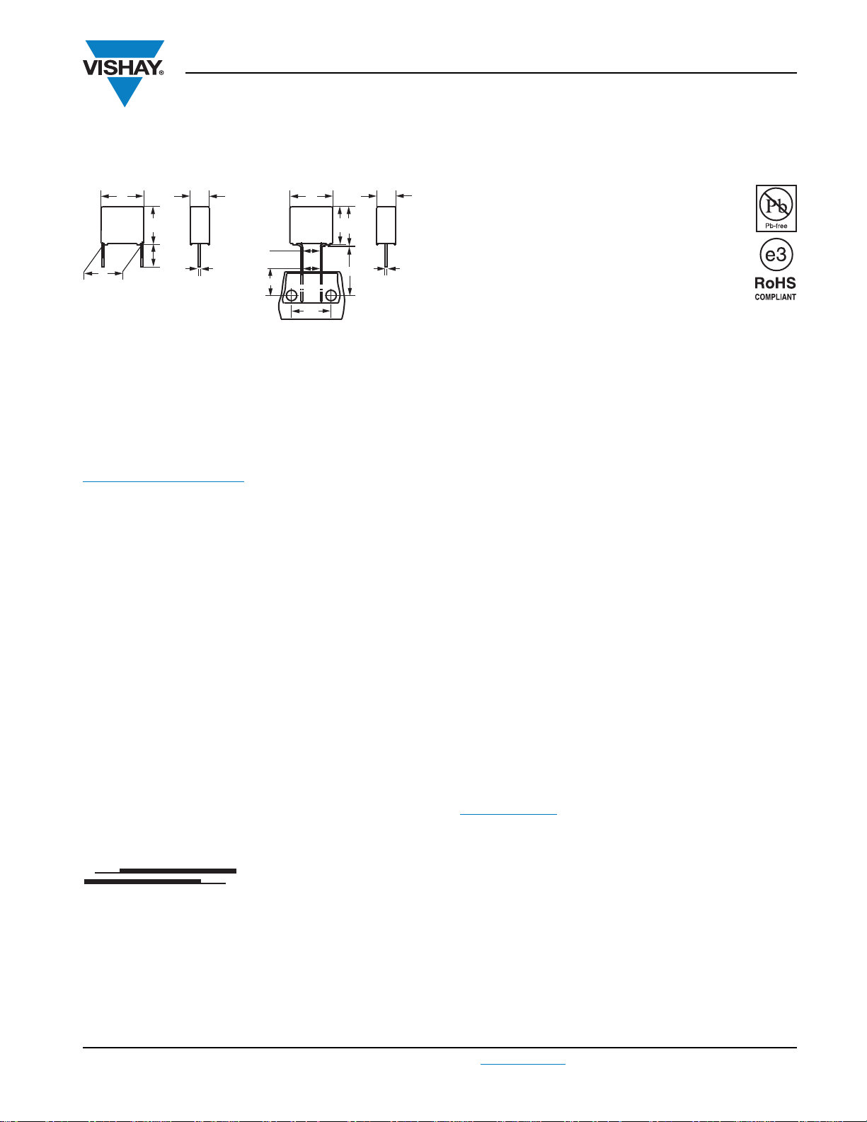
Interference Suppression Film Capacitors
w
Ø d
t
P
h
ll
h
h'
w
Ø d
t
H
F
10
F'
(1)
15
l
t
MKP Radial Potted Type
Dimensions in mm
Note
(1)
|F - F’| < 0.3 mm
F = 7.5 mm + 0.6 mm/- 0.1 mm
APPLICATIONS
For standard across the line X1 applications.
See also Application Note:
www.vishay.com/doc?28153
MKP338 1 X1
Vishay BCcomponents
FEATURES
15 mm to 27.5 mm lead pitch and 15 mm bent
back to 7.5 mm
Supplied loose in box, taped on ammopack or
reel
Compliant to RoHS Directive 2002/95/EC
PERMISSIBLE DC VOLTAGE
DC 1000 V
ENCAPSULATION
Plastic case, epoxy resin sealed, flame retardant
UL-class 94 V-0
CLIMATIC TESTING CLASS ACC. TO
IEC 60068-1
55/105/56/B
REFERENCE STANDARDS
“IEC 60384-14 ed-3 and EN 60384-14”
“IEC 60065, pass. flamm. class B”
UL1414; UL1283; CSA-C22.2 No. 8
MARKING
C-value; tolerance; rated voltage; sub-class; manufacturer’s
type designation; code for dielectric material; manufacturer
location; manufacturer’s logo; year, week and safety
approvals.
DIELECTRIC
Polypropylene film
ELECTRODES
Metallized film
CONSTRUCTION
Mono construction
RATED VOLTAGE
AC 440 V; 50 Hz to 60 Hz
CAPACITANCE RANGE (E12 SERIES)
E12 series 0.01 µF to 1 µF
Preferred values acc. to E6
CAPACITANCE TOLERANCE
± 20 %; ± 10 %; ± 5 %
LEADS
Tinned wire
MAXIMUM APPLICATION TEMPERATURE
105 °C
DETAIL SPECIFICATION
For more detailed data and test requirements contact:
RFI@vishay.com
www.vishay.com
Document Number: 28116 For technical questions, contact: RFI@vishay.com
Revision: 23-Feb-11 383
MKP338 1 X1
Example:
104 = 10 x 10 = 100 nF
(except special numbers)
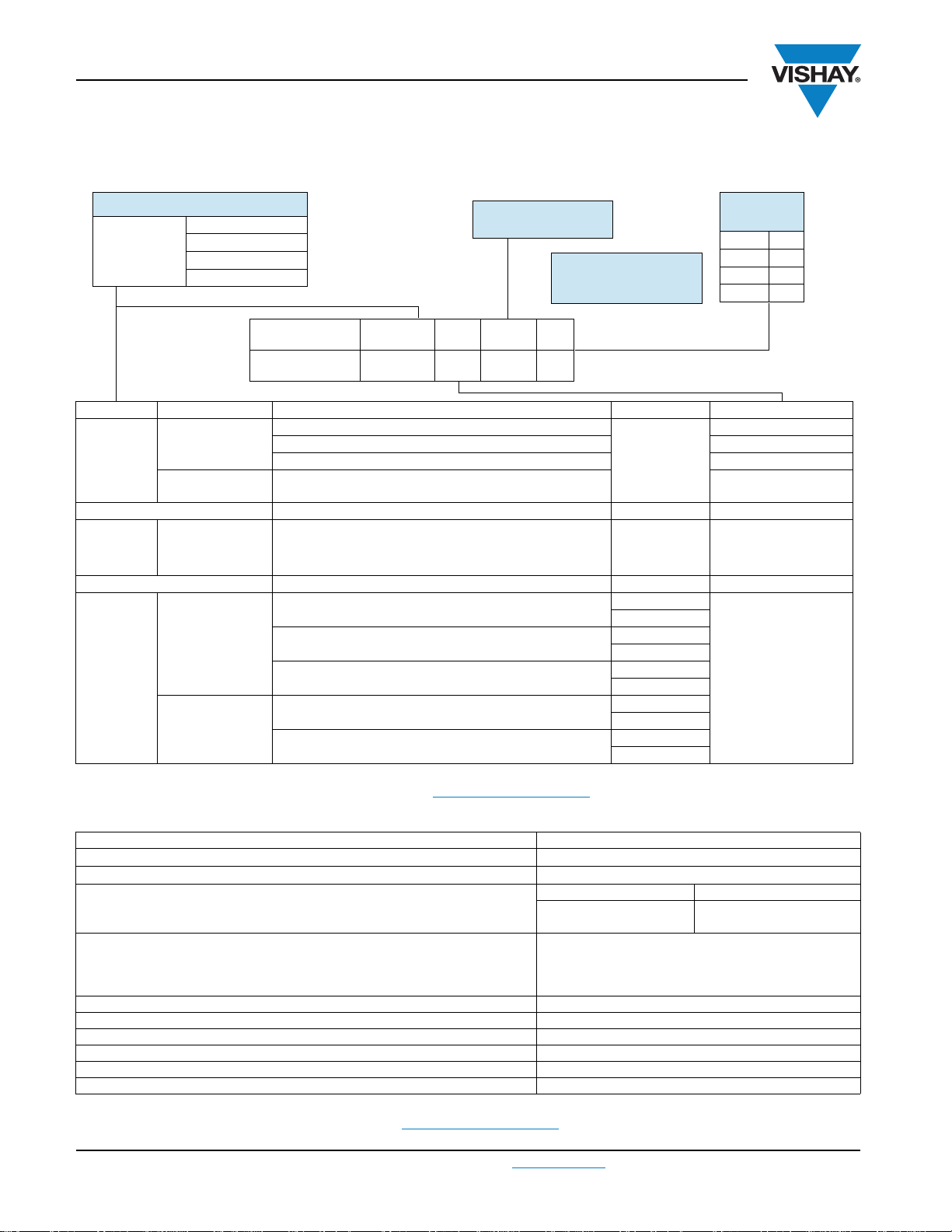
BFC2 338 1X XX X
2222
(*)
338 1X XX X
TYPE PACKAGING LEAD CONFIGURATION C-TOL PREFERRED TYPES
338 1
X1
Loose in box
Lead length 3.5 mm ± 0.3 mm
± 20 %
BFC2 338 10 ...
Lead length 5.0 mm ± 1.0 mm BFC2 338 12 ...
Lead length 25.0 mm ± 2.0 mm BFC2 338 14 ...
Taped on reel
(1)
Bent back to 7.5 mm;
H = 16.0 mm; P
0
= 15.0 mm; reel diameter = 500 mm
BFC2 338 16 ...
ALTERNATIVE TAPED VERSIONS ON REQUEST
338 1
X1
X1
Taped on reel
(1)
H = 18.5 mm; for P0 12.7 mm; reel diameter 500 mm ± 20 % BFC2 338 17 ...
ALTERNATIVE C-TOL. ON REQUEST
338 1
X1
Loose in box
Lead length 3.5 mm ±0.3 mm
± 10 %
See tables for detail
± 5 %
Lead length 5.0 mm ±1.0 mm
± 10 %
± 5 %
Lead length 25.0 mm ±2.0 mm
± 10 %
± 5 %
Taped on reel
(1)
Bent back to 7.5 mm; ± 10 %
H = 16.0 mm; P
0
= 15.0 mm; reel diameter = 500 mm ± 5 %
H = 18.5 mm; P
0
= 12.7 mm; reel diameter = 500 mm
± 10 %
± 5 %
TYPE AND PITCHES
338 1
X1
7.5 mm (bent back)
15.0 mm
22.5 mm
27.5 mm
MULTIPLIER
(nF)
0.1 2
13
10 4
100 5
CAPACITANCE
(numerically)
(*) Old ordering code
Vishay BCcomponents
Interference Suppression Film Capacitors
COMPOSITION OF CATALOG NUMBER
MKP Radial Potted Type
Note
(1)
For detailed tape specification refer to Packaging Information: www.vishay.com/doc?28139
SPECIFIC REFERENCE DATA
DESCRIPTION VAL UE
Rated AC voltage (U
Permissible DC voltage (U
Tangent of loss angle: at 1 kHz at 10 kHz
C 470 nF 10 x 10
C 470 nF 20 x 10
Rated voltage pulse slope (dU/dt)R at 615 V
Pitch = 15 mm and 7.5 mm (bent back)
Pitch=22.5mm
Pitch=27.5mm
R between leads, for C 0.33 µF at 100 V, 1 min > 15 000 M
RC between leads, for C > 0.33 µF at 100 V, 1 min >5000 s
R between leads and case, 100 V, 1 min > 30 000 M
Withstanding (DC) voltage (cut off current 10 mA), rise time 1000 V/s 3400 V, 1 min
Withstanding (AC) voltage between leads and case 2380 V, 1 min
Maximum application temperature 105 °C
Note
(1)
See “Voltage Proof Test for Metallized Film Capacitors”: www.vishay.com/doc?28169
www.vishay.com For technical questions, contact: RFI@vishay.com
384 Revision: 23-Feb-11
RAC
)
)
RDC
DC
440 V
1000 V
-4
-4
250 V/µs
150 V/µs
100 V/µs
Document Number: 28116
20 x 10
70 x 10
-4
-4
MKP338 1 X1
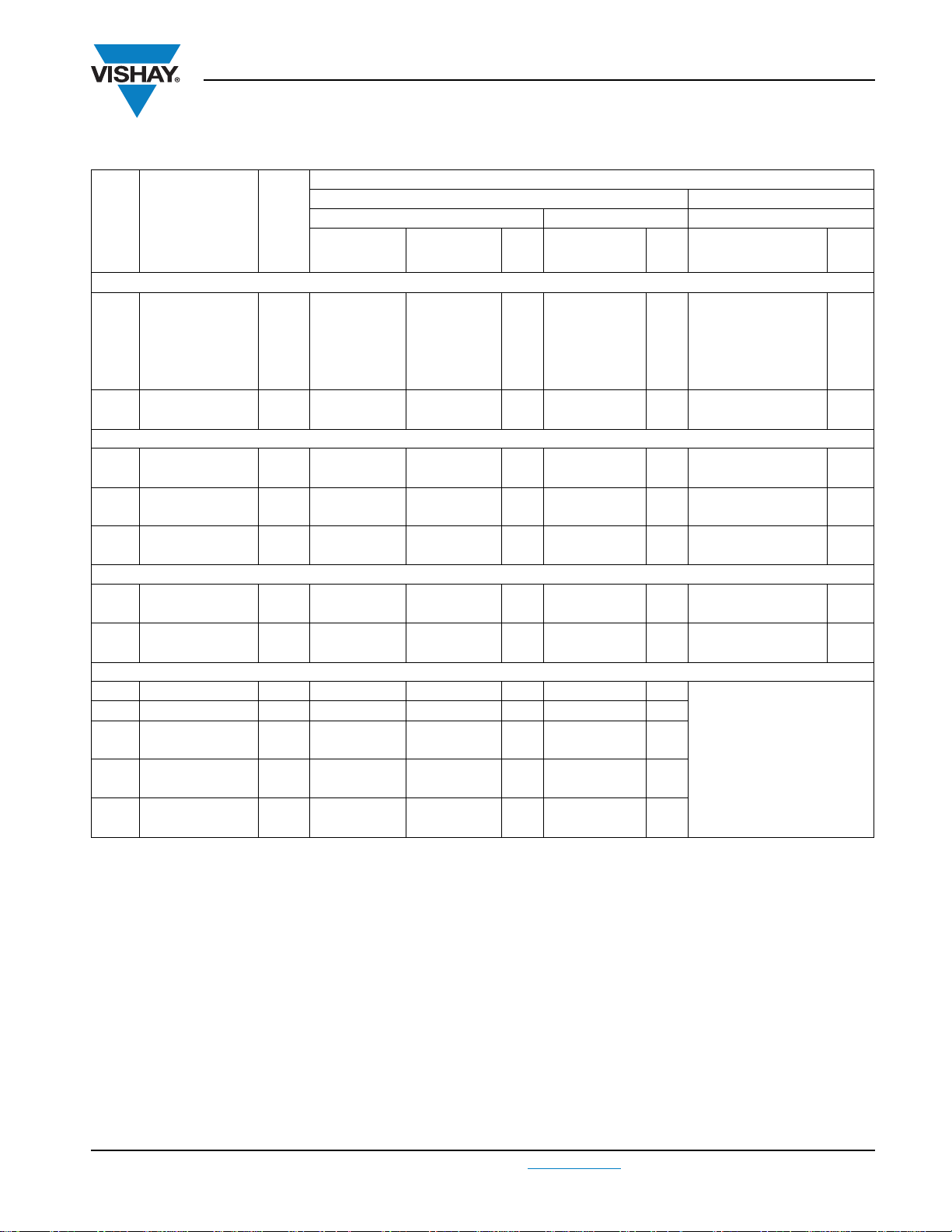
Interference Suppression Film Capacitors
Vishay BCcomponents
MKP Radial Potted Type
C-tol. = ± 20 %
CATALOG NUMBER BFC2 338 1XXXX AND PACKAGING
C
(µF)
Pitch = 15.0 mm ± 0.4 mm; d
0.01
0.012 10123 12123 14123 17123
0.015 10153 12153 14153 17153
0.018 10183 12183 14183 17183
0.022 10223 12223 14223 17223
0.027
0.033 10333 12333 14333 17333
Pitch = 15.0 mm ± 0.4 mm; d
0.039
0.047 10473 12473 14473 17473
0.056
0.068 10683 12683 14683 17683
0.082
0.1 10104 12104 14104 17104
Pitch = 22.5 mm ± 0.4 mm; d
0.12
0.15 10154 12154 14154 17154
0.18
0.22 10224 12224 14224 17224
Pitch = 27.5 mm ± 0.4 mm; d
0.27 11.0 x 21.0 x 31.0 7.4 10274 12274 100 14274 125
0.33 13.0 x 23.0 x 31.0 9.2 10334 12334 100 14334 125
0.39
0.47 10474 12474 14474
0.56
0.68 10684 12684 14684
0.82
1.00 10105 12105 14105
DIMENSIONS
w x h x l
(mm)
5.0 x 11.0 x 17.5 1.0
6.0 x 12.0 x 17.5 1.4
7.0 x 13.5 x 17.5 1.8
8.5 x 15.0 x 17.5 2.4
10.0 x 16.5 x 17.5 3.0
8.5 x 18.0 x 26.0 3.8
10.0 x 19.5 x 26.0 6.8
15.0 x 25.0 x 31.5 12.3
18.0 x 28.0 x 31.5 16.1
21.0 x 31.0 x 31.0 20.3
MASS
(3)
(g)
= 0.60 mm ± 0.06 mm
t
= 0.80 mm ± 0.08 mm
t
= 0.80 mm ± 0.08 mm
t
= 0.80 mm ± 0.08 mm
t
lt =
3.5 mm ±
0.3 mm
10103 12103
10273 12273
10393 12393
10563 12563
10823 12823
10124 12124
10184 12184
10394 12394
10564 12564
10824 12824
Short leads Long leads Reel diameter = 500 mm
LOOSE IN BOX TAPED
lt =
5.0 mm ±
1.0 mm
SPQ
1000
1000
750
750
500
200
200
100
100
50
lt=
25.0 mm ±
2.0 mm
14103
14273
14393
14563
14823
14124
14184
14394
14564
14824
SPQ
1000
1000
500
500
450
250
200
125
100
75
H = 18.5 mm;
P
= 12.7 mm
0
17103
17273
17393
17563
17823
17124
17184
(1)(2)
SPQ
1100
900
800
650
600
450
350
Notes
• SPQ = Standard Packing Quantity
(1)
H = in-tape height; P0 = sprocket hole distance; for detailed specifications refer to “Packaging Information”
(2)
Reel diameter = 356 mm is available on request
(3)
Weight for short lead product only
Document Number: 28116 For technical questions, contact: RFI@vishay.com
Revision: 23-Feb-11 385
www.vishay.com
MKP338 1 X1
Vishay BCcomponents
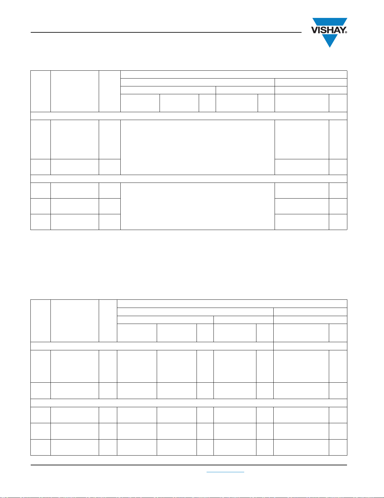
Interference Suppression Film Capacitors
MKP Radial Potted Type
Bent back pitch 7.5 mm (only taped); C-tol. = ± 20 %
CATALOG NUMBER BFC2 338 1XXXX AND PACKAGING
LOOSE IN BOX TAPED
lt =
5.0 mm ±
1.0 mm
= 0.60 mm ± 0.06 mm
t
= 0.80 mm ± 0.08 mm
t
SPQ
lt=
25.0 mm ±
2.0 mm
SPQ
H = 16.0 mm;
P
= 15.0 mm
0
C
(µF)
DIMENSIONS
w x h x l
(mm)
MASS
(3)
(g)
lt =
3.5 mm ±
0.3 mm
Short leads Long leads Reel diameter = 500 mm
Original pitch = 15.0 mm; bent back pitch = 7.5 mm ± 0.4 mm; d
0.010
0.012 16123
0.015 16153
5.0 x 13.0 x 17.5 1.0
0.018 16183
0.022 16223
0.027
0.033 16333
6.0 x 14.0 x 17.5 1.4
Original pitch = 15.0 mm; bent back pitch = 7.5 mm ± 0.4 mm; d
0.039
0.047 16473
0.056
0.068 16683
0.082
0.100 16104
7.0 x 15.5 x 17.5 1.8
8.5 x 17.0 x 17.5 1.4
10.0 x 18.5 x 17.5 3.0
Notes
• SPQ = Standard Packing Quantity
(1)
H = in-tape height; P0 = sprocket hole distance; for detailed specifications refer to “Packaging Information”
(2)
Reel diameter = 356 mm is available on request
(3)
Weight for short lead product only
16103
16273
16393
16563
16823
(1)(2)
SPQ
950
800
700
550
500
C-tol. = ± 10 %
CATALOG NUMBER BFC2 338 1XXXX AND PACKAGING
LOOSE IN BOX TAPED
lt =
5.0 mm ±
1.0 mm
SPQ
lt=
25.0 mm ±
2.0 mm
SPQ
H = 18.5 mm;
= 12.7 mm
P
0
18514
1000
1000
750
750
500
18518
18521
18523
18525
1000
1000
500
500
450
Document Number: 28116
18914
18918
18921
18923
18925
(1)(2)
SPQ
1100
900
800
650
600
C
(µF)
DIMENSIONS
w x h x l
(mm)
MASS
(3)
(g)
lt =
3.5 mm ±
Short leads Long leads Reel diameter = 500 mm
0.3 mm
Pitch = 15.0 mm ± 0.4 mm; d
0.010
0.012 18115 18315 18515 18915
0.015 18116 18316 18516 18916
5.0 x 11.0 x 17.5 1.0
=0.60mm ± 0.06mm
t
18114 18314
0.018 18117 18317 18517 18917
0.022
0.027 18119 18319 18519 18919
Pitch = 15.0 mm ± 0.4 mm; d
0.033
0.039 18122 18322 18522 18922
0.047
0.056 18124 18324 18524 18924
0.068
0.082 18126 18326 18526 18926
6.0 x 12.0 x 17.5 1.4
=0.80mm ± 0.08mm
t
7.0 x 13.5 x 17.5 1.8
8.5 x 15.0 x 17.5 2.4
10.0 x 16.5 x 17.5 3.0
18118 18318
18121 18321
18123 18323
18125 18325
www.vishay.com For technical questions, contact: RFI@vishay.com
386 Revision: 23-Feb-11
MKP338 1 X1
Interference Suppression Film Capacitors
Vishay BCcomponents
MKP Radial Potted Type
CATALOG NUMBER BFC2 338 1XXXX AND PACKAGING
LOOSE IN BOX TAPED
lt =
5.0 mm ±
1.0 mm
SPQ
200
100
100
100
lt=
25.0 mm ±
2.0 mm
18528
18532
18535
18537
SPQ
250
125
125
100
H = 18.5 mm;
P
0
= 12.7 mm
18928
(1)(2)
SPQ
450
C
(µF)
DIMENSIONS
w x h x l
(mm)
MASS
(3)
(g)
lt =
3.5 mm ±
Short leads Long leads Reel diameter = 500 mm
0.3 mm
Pitch = 22.5 mm ± 0.4 mm; d
= 0.80 mm ± 0.08 mm
t
0.10 7.0 x 16.5 x 26.0 2.9 18127 18327 200 18527 250 18927 550
0.12
0.15 18129 18329 18529 18929
8.5 x 18.0 x 26.0 3.8
18128 18328
0.18 10.0 x 19.5 x 26.0 6.8 18131 18331 200 18531 200 18931 350
Pitch = 27.5 mm ± 0.4 mm; d
0.22
0.27 18133 18333 18533
11.0 x 21.0 x 31.0 7.4
= 0.80 mm ± 0.08 mm
t
18132 18332
0.33 13.0 x 23.0 x 31.0 9.2 18134 18334 100 18534 125
0.39
0.47 18136 18336 18536
0.56
0.68 18138 18338 18538
15.0 x 25.0 x 31.0 12.3
18.0 x 28.0 x 31.0 16.1
18135 18335
18137 18337
0.82 21.0 x 31.0 x 31.0 20.3 18139 18339 50 18539 75
Notes
• SPQ = Standard Packing Quantity
(1)
H = in-tape height; P0 = sprocket hole distance; for detailed specifications refer to “Packaging Information”
(2)
Reel diameter = 356 mm is available on request
(3)
Weight for short lead product only
Bent back pitch 7.5 mm (only taped); C-tol. = ± 10 %
CATALOG NUMBER BFC2 338 1XXXX AND PACKAGING
C
(µF)
DIMENSIONS
w x h x l
(mm)
MASS
(3)
(g)
lt =
3.5 mm ±
0.3 mm
Short leads Long leads
Original pitch = 15.0 mm; bent back pitch = 7.5 mm ± 0.4 mm; d
0.010
0.012 18715
0.015 18716
5.0 x 13.0 x 17.5 1.0
0.018 18717
0.022
0.027 18719
6.0 x 14.0 x 17.5 1.4
Original pitch = 15.0 mm; bent back pitch = 7.5 mm ± 0.4 mm; d
0.033
0.039 18722
0.047
0.056 18724
0.068
0.082 18726
7.0 x 15.5 x 17.5 1.8
8.5 x 17.0 x 17.5 2.4
10.0 x 18.5 x 17.5 3.0
Notes
• SPQ = Standard Packing Quantity
(1)
H = in-tape height; P0 = sprocket hole distance; for detailed specifications refer to “Packaging Information”
(2)
Reel diameter = 356 mm is available on request
(3)
Weight for short lead product only
LOOSE IN BOX TAPED
Reel diameter = 500 mm
lt =
5.0 mm ±
1.0 mm
SPQ
= 0.60 mm ± 0.06 mm
t
= 0.80 mm ± 0.08 mm
t
lt=
25.0 mm ±
2.0 mm
SPQ
H = 18.5 mm;
P
0
= 12.7 mm
18714
18718
18721
18723
18725
(1)(2)
SPQ
950
800
700
550
500
Document Number: 28116 For technical questions, contact: RFI@vishay.com
www.vishay.com
Revision: 23-Feb-11 387

MKP338 1 X1
Vishay BCcomponents
Interference Suppression Film Capacitors
MKP Radial Potted Type
C-tol. = ± 5 %
CATALOG NUMBER BFC2 338 1XXXX AND PACKAGING
C
(µF)
DIMENSIONS
w x h x l
(mm)
Pitch = 15.0 mm ± 0.4 mm; d
0.010
0.012 18215 18415 18615 18935
0.015 18216 18416 18616 18936
5.0 x 11.0 x 17.5 1.0
MASS
(3)
(g)
=0.60mm ± 0.06mm
t
lt =
3.5 mm ±
0.3 mm
18214 18414
Short leads Long leads Reel diameter = 500 mm
0.018 18217 18417 18617 18937
0.022
0.027 18219 18419 18619 18939
Pitch = 15.0 mm ± 0.4 mm; d
0.033
0.039 18222 18422 18622 18942
0.047
0.056 18224 18424 18624 18944
0.068
0.082 18226 18426 18626 18946
Pitch = 22.5 mm ± 0.4 mm; d
0.10
0.12 18228 18428 18628 18948
0.15
0.18 18231 18431 18631 18951
Pitch = 27.5 mm ± 0.4 mm; d
6.0 x 12.0 x 17.5 1.4
=0.80mm ± 0.08mm
t
7.0 x 13.5 x 17.5 1.8
8.5 x 15.0 x 17.5 2.4
10.0 x 16.5 x 17.5 3.0
=0.80mm ± 0.08mm
t
8.5 x 18.0 x 26.0 3.8
10.0 x 19.5 x 26.0 6.8
=0.80mm ± 0.08mm
t
18218 18418
18221 18421
18223 18423
18225 18425
18227 18427
18229 18429
0.22 11.0 x 21.0 x 31.0 7.4 18232 18432 100 18632 125
0.27
0.33 18234 18434 18634
0.39
0.47 18236 18436 18636
0.56
0.68 18238 18438 18638
13.0 x 23.0 x 31.0 9.2
15.0 x 25.0 x 31.5 12.3
18.0 x 28.0 x 31.5 16.1
18233 18433
18235 18435
18237 18437
0.82 21.0 x 31.0 x 31.0 20.3 18239 18439 50 18639 75
Notes
• SPQ = Standard Packing Quantity
(1)
H = in-tape height; P0 = sprocket hole distance; for detailed specifications refer to “Packaging Information”
(2)
Reel diameter = 356 mm is available on request
(3)
Weight for short lead product only
Bent back pitch (only taped); C-tol. = ± 5 %
C
(µF)
DIMENSIONS
w x h x l
(mm)
MASS
(3)
(g)
lt =
3.5 mm ±
Short leads Long leads Reel diameter = 500 mm
0.3 mm
Original pitch = 15.0 mm; bent back pitch = 7.5 ± 0.4 mm; d
0.010
0.012 18815
0.015 18816
5.0 x 13.0 x 17.5 1.0
0.018 18817
0.022
0.027 18819
6.0 x 14.0 x 17.5 1.4
Original pitch = 15.0 mm; bent back pitch = 7.5 ± 0.4 mm; d
0.033
0.039 18822
0.047
0.056 18824
0.068
0.082 18826
Notes
• SPQ = Standard Packing Quantity
(1)
H = in-tape height; P0 = sprocket hole distance; for detailed specifications refer to “Packaging Information”
(2)
Reel diameter = 356 mm is available on request
(3)
Weight for short lead product only
7.0 x 15.5 x 17.5 1.8
8.5 x 17.0 x 17.5 2.4
10.0 x 18.5 x 17.5 3.0
www.vishay.com For technical questions, contact: RFI@vishay.com
388 Revision: 23-Feb-11
LOOSE IN BOX TAPED
lt =
5.0 mm ±
1.0 mm
SPQ
1000
1000
750
750
500
200
200
100
100
100
lt=
25.0 mm ±
2.0 mm
18614
18618
18621
18623
18625
18627
18629
18633
18635
18637
SPQ
1000
1000
500
500
450
250
200
125
125
100
H = 18.5 mm;
P
= 12.7 mm
0
18934
18938
18941
18943
18945
18947
18949
CATALOG NUMBER BFC2 338 1XXXX AND PACKAGING
LOOSE IN BOX TAPED
lt =
5.0 mm ±
1.0 mm
= 0.60 ± 0.06 mm
t
= 0.80 ± 0.08 mm
t
SPQ
lt=
25.0 mm ±
2.0 mm
SPQ
H = 16.0 mm;
= 15.0 mm
P
0
Document Number: 28116
18814
18818
18821
18823
18825
(1)(2)
SPQ
1100
900
800
650
600
450
350
(1)
SPQ
950
800
700
550
500

MKP338 1 X1
CBA116
Eccentricity
w
max.
= W + Δ
h
max.
= h + Δ
I
max.
= I + Δ
Seating plane
Interference Suppression Film Capacitors
Vishay BCcomponents
MKP Radial Potted Type
APPROVALS
SAFETY APPROVALS X1 VOLTAGE VALUE FILE NUMBERS
EN 60384-14 (ENEC)
(= IEC 60384-14 ed-3)
UL1414 250 V
UL1283
UL1283 and (CSA-C22.2 No. 8) 440 V
CB-Test Certificate
The ENEC-approval together with the CB-Certificate replace all national marks of the following countries (they have already signed the
ENEC-Agreement): Austria; Belgium; Czech. Republic; Denmark; Finland; France; Germany; Greece; Hungary; Ireland; Italy; Luxembourg;
Netherlands; Norway; Portugal; Slovenian; Spain; Switzerland and United Kingdom.
440 V
440 V
440 V
AC
AC
AC
AC
AC
10 nF to 1 µF FI 2008060 A1
10 nF to 1 µF E112471
10 nF to 100 nF E109565
100 nF to 1 µF E109565
10 nF to 1 µF FI 5256 A1
®
16
MOUNTING
Normal Use
The capacitors are designed for mounting on printed-circuit boards. The capacitors packed in bandoliers are designed for
mounting in printed-circuit boards by means of automatic insertion machines.
For detailed tape specifications refer to: “Packaging Information”: www.vishay.com/doc?28139
Specific Method of Mounting to Withstand Vibration and Shock
In order to withstand vibration and shock tests, it must be ensured that the stand-off pips are in good contact with the
printed-circuit board:
For pitches 15 mm capacitors shall be mechanically fixed by the leads
For longer pitches the capacitors shall be mounted in the same way and the body clamped
Space Requirements on Printed Circuit Board
The maximum space for length (I
board is shown in the drawings.
For products with pitch 15 mm, w = l = 0.3 mm; h = 0.1 mm
Eccentricity defined as in drawing. The maximum eccentricity is smaller than or equal to the lead diameter of the product
concerned.
), width (w
max.
) and heigth (h
max.
) of film capacitors to take in account on the printed circuit
max.
SOLDERING
For general soldering conditions and wave soldering profile, we refer to the application note:
“Soldering Guidelines for Film Capacitors”: www.vishay.com/doc?28171
Storage Temperature
Storage temperature: T
Ratings and Characteristics Reference Conditions
Unless otherwise specified, all electrical values apply to an ambient temperature of 23 °C ± 1 °C, an atmospheric pressure of
86 kPa to 106 kPa and a relative humidity of 50 % ± 2 %.
For reference testing, a conditioning period shall be applied over 96 h ± 4 h by heating the products in a circulating air oven at
the rated temperature and a relative humidity not exceeding 20 %.
Document Number: 28116 For technical questions, contact: RFI@vishay.com
Revision: 23-Feb-11 389
= - 25 °C to + 40 °C with RH maximum 80 % without condensation
stg
www.vishay.com

MKP338 1 X1
typical
- 50
ΔC/C
(%)
2
- 2
- 4
- 6
0
050100T
amb
(°C)
4
min.
max.
Dissipation
Factor (x 10
- 4
)
10
10
10
10
10 10
10
1010
1
234
5
0
1
2
3
f(Hz)
C = 1
µF
220 nF < C < 1µF
47 nF < C ≤ 220 nF
10 nF < C ≤ 47 nF
10
0
10
-1
10
2
10
1
f (Mhz)
10
100 1000 10 000
°C (nF)
X 1
1
T
amb
≤ 105 °C
AC voltage
(V)
10
3
10
2
10
1
f (Hz)
10
1
10
2
10
3
10
4
10
5
10
2
10
3
10
4
10
1
10
0
10
-1
10
2
10
1
10
3
10
4
10
5
f (Hz)
470 nF
100 nF
47 nF
10 nF
1000 nF
1 nF
4.7 nF
AC current
(mA)
T
amb
≤ 105 °C
Vishay BCcomponents
Interference Suppression Film Capacitors
MKP Radial Potted Type
CHARACTERISTICS
Capacitance as a function of ambient temperature (typical curve) Tangent of loss angle as a function of frequency (typical curve)
Impedance as a function of frequency (typical curve) Resonant frequency as a function of capacitance (typical curve)
3
10
2
10
Impedance
(Ω)
10 nF
47 nF
1
10
100 nF
470 nF
1000 nF
0
10
-1
10
-2
10
10
4
10
5
10
6
7
10
f (Hz)
8
10
Max. RMS voltage as a function of frequency Max. RMS current as a function of frequency
www.vishay.com For technical questions, contact: RFI@vishay.com
390 Revision: 23-Feb-11
Document Number: 28116

MKP338 1 X1
APPLICATION NOTES
Interference Suppression Film Capacitors
MKP Radial Potted Type
Insulation resistance as a function of ambient temperature
6
10
RC (s)
5
10
4
10
0
20 40 60
80
100
(°C)
T
amb
Vishay BCcomponents
For X1 electromagnetics interference suppression in standard across the line applications (50 Hz/60 Hz) with a maximum
mains voltage of 440 V
AC
.
For series impedance applications we refer to Application Note www.vishay.com/doc?28153
For capacitors connected in parallel, normally the proof voltage and possibly the rated voltage must be reduced. For information
depending of the capacitance value and the number of parallel connections contact: dc-film@vishay.com
These capacitors are not intended for continuous pulse applications. For these situations, capacitors of the AC and pulse
programs must be used.
The maximum ambient temperature must not exceed 105 °C.
Rated voltage pulse slope:
If the pulse voltage is lower than the rated voltage, the values of the specific reference data can be multiplied by 615 VDC and
divided by the applied voltage.
Document Number: 28116 For technical questions, contact: RFI@vishay.com
Revision: 23-Feb-11 391
www.vishay.com

MKP338 1 X1
Vishay BCcomponents
Interference Suppression Film Capacitors
MKP Radial Potted Type
INSPECTION REQUIREMENTS
General Notes:
1. Sub-clause numbers of tests and performance requirements refer to the “Sectional Specification, Publication
IEC 60384-14 ed-3 and Specific Reference Data.”
Group C Inspection Requirements
SUB-CLAUSE NUMBER
AND TEST
SUB-GROUP C1A PART OF SAMPLE OF
SUB-GROUP C1
4.1 Dimensions (detail) As specified in chapters “General data” of
Initial measurements Capacitance
4.3 Robustness o terminations Tensile: load 10 N; 10 s
4.4 Resistance to soldering heat No pre-drying
4.19 Component solvent resistance Isopropylalcohol at room temperature
4.4.2 Final measurements Visual examination No visible damage
SUB-GROUP C1B PART OF SAMPLE OF
SUB-GROUP C1
Initial measurements Capacitance
4.20 Solvent resistance of the marking Isopropylalcohol at room temperature
4.6 Rapid change of temperature A = - 55 °C
CONDITIONS PERFORMANCE REQUIREMENTS
this specification
Tangent of loss angle at 10 kHz
Bending: load 5 N; 4 x 90°
Method: 1A
Solder bath: 280 °C ± 5 °C
Duration: 10 s
Method: 2
Immersion time: 5 min ± 0.5 min
Recovery time:
Min. 1 h, max. 2 h
Capacitance C/C| 5 % of the value measured initially
Tangent of loss angle Increase of tan 0.008
Insulation resistance As specified in section “Insulation
Tangent of loss angle at 10 kHz
Method: 1
Rubbing material: cotton wool
Immersion time: 5 min ± 0.5 min
B = + 105 °C
5 cycles
Duration t = 30 min
No visible damage
Legible marking
Compared to values measured initially
Resistance” of this specification
No visible damage
Legible marking
www.vishay.com For technical questions, contact: RFI@vishay.com
392 Revision: 23-Feb-11
Document Number: 28116

MKP338 1 X1
Interference Suppression Film Capacitors
Vishay BCcomponents
MKP Radial Potted Type
SUB-CLAUSE NUMBER
AND TEST
4.6.1 Inspection
4.7 Vibration
4.7.2 Final inspection Visual examination No visible damage
4.9 Shock Mounting: See section “Mounting” for more
4.9.2 Final measurements Visual examination No visible damage
SUB-GROUP C1 COMBINED SAMPLE OF
SPECIMENS OF SUB-GROUPS C1A AND
C1B
4.11 Climatic sequence
4.11.1 Initial measurements Capacitance
4.11.2 Dry heat Temperature: 105 °C
4.11.3 Damp heat cyclic
Tes t Db
First cycle
4.11.4 Cold Temperature: - 55 °C
4.11.5 Damp heat cyclic
Tes t Db
Remaining cycles
4.11.6 Final measurements Visual examination No visible damage
CONDITIONS PERFORMANCE REQUIREMENTS
Visual examination
Mounting: See section “Mounting” of this
specification
Procedure B4
Frequency range: 10 Hz to 55 Hz
Amplitude: 0.75 mm or
Acceleration 98 m/s²
(whichever is less severe)
Total duration 6 h
information
Pulse shape: half sine
Acceleration: 490 m/s²
Duration of pulse: 11 ms
Capacitance C/C| 5 % of the value measured initially
Tangent of loss angle Increase of tan 0.008
Insulation resistance As specified in section “Insulation
Measured in 4.4.2 and 4.9.2
Tangent of loss angle:
Measured initially in C1A and C1B
Duration: 16 h
Duration: 2 h
Capacitance C/C| 5 % of the value measured in
Tangent of loss angle Increase of tan 0.008
Voltage proof
1900 V
Insulation resistance 50 % of values specified in section
; 1 min between terminations
DC
No visible damage
Compared to values measured initially
Resistance” of this specification
Legible marking
4.11.1.
Compared to values measured in
4.11.1.
No permanent breakdown or flash-over
“Insulation Resistance” of this specification
Document Number: 28116 For technical questions, contact: RFI@vishay.com
Revision: 23-Feb-11 393
www.vishay.com

MKP338 1 X1
R
615 V
DC
1.5 x C (dU/dt)
---------------------------------------
=
Vishay BCcomponents
Interference Suppression Film Capacitors
MKP Radial Potted Type
SUB-CLAUSE NUMBER
AND TEST
SUB-GROUP C2
4.12 Damp heat steady state 56 days, 40 °C, 90 % to 95 % RH
4.12.1 Initial measurements Capacitance
4.12.3 Final measurements Visual examination No visible damage
SUB-GROUP C3
4.13.1 Initial measurements Capacitance
4.13 Impulse voltage 3 successive impulses, full wave, peak
4.14 Endurance Duration: 1000 h
4.14.7 Final measurements Visual examination No visible damage
SUB-GROUP C4
4.15 Charge and discharge
CONDITIONS PERFORMANCE REQUIREMENTS
No load
Tangent of loss angle at 1 kHz
Legible marking
Capacitance |C/C| 5 % of the value measured in
Tangent of loss angle Increase of tan 0.008
Voltage proof
1900 V
Insulation resistance 50 % of values specified in section
Tangent of loss angle at 10 kHz
voltage:
X1: 4 kV
Max. 24 pulses
1.25 x U
Once in every hour the voltage is increased
to 1000 V
47 ± 5 %
Capacitance |C/C| 10 % compared to values
Tangent of loss angle Increase of tan 0.008
Voltage proof
Insulation resistance 50 % of values specified in section
10 000 cycles
Charged to 615 V
Discharge resistance:
; 1 min between terminations
DC
at 105 °C
RAC
for 0.1 s via resistor of
RMS
1900 V
2380 V
and case.
; 1 min between terminations
DC
; 1 min between terminations
AC
DC
4.12.1.
Compared to values measured in
4.12.1.
No permanent breakdown or flash-over
“Insulation Resistance” of this specification
No self healing breakdowns or flash-over
Legible marking
measured in 4.13.1.
Compared to values measured in 4.13.1.
No permanent breakdown or flash-over
“Insulation Resistance” of this specification
4.15.1 Initial measurements Capacitance
www.vishay.com For technical questions, contact: RFI@vishay.com
394 Revision: 23-Feb-11
Tangent of loss angle at 10 kHz
Document Number: 28116

MKP338 1 X1
Interference Suppression Film Capacitors
Vishay BCcomponents
MKP Radial Potted Type
SUB-CLAUSE NUMBER
AND TEST
4.15.3 Final measurements Capacitance |C/C| 10 % compared to values
SUB-GROUP C5
4.16 Radio frequency characteristic Resonance frequency 0.9 times value as specified in section
SUB-GROUP C6
4.17 Passive flammability
Class B
CONDITIONS PERFORMANCE REQUIREMENTS
measured in 4.15.1.
Tangent of loss angle Increase of tan 0.008
Insulation resistance 50 % of values specified in section
Bore of gas jet: Ø 0.5 mm
Fuel: Butane
Test duration for actual volume V in mm³:
V 250: 10 s
250 < V 500: 20 s
500 < V 1750: 30 s
V > 1750: 60 s
One flame application
Compared to values measured in 4.15.1.
“Insulation Resistance” of this specification
“Resonant Frequency” of this specification
After removing test flame from capacitor,
the capacitor must not continue to burn for
more than 10 s. No burning particle must
drop from the sample.
12 mm
~ 8 mm
45.0°
SUB-GROUP C7
4.18 Active flammability 20 cycles of 4 kV discharges on the test
capacitor connected to U
RAC
The cheese cloth around the capacitors
shall not burn with a flame.
No electrical measurements are required.
Document Number: 28116 For technical questions, contact: RFI@vishay.com
Revision: 23-Feb-11 395
www.vishay.com

Legal Disclaimer Notice
Vishay
Disclaimer
ALL PRODUCT, PRODUCT SPECIFICATIONS AND DATA ARE SUBJECT TO CHANGE WITHOUT NOTICE TO IMPROVE
RELIABILITY, FUNCTION OR DESIGN OR OTHERWISE.
Vishay Intertechnology, Inc., its affiliates, agents, and employees, and all persons acting on its or their behalf (collectively,
“Vishay”), disclaim any and all liability for any errors, inaccuracies or incompleteness contained in any datasheet or in any other
disclosure relating to any product.
Vishay makes no warranty, representation or guarantee regarding the suitability of the products for any particular purpose or
the continuing production of any product. To the maximum extent permitted by applicable law, Vishay disclaims (i) any and all
liability arising out of the application or use of any product, (ii) any and all liability, including without limitation special,
consequential or incidental damages, and (iii) any and all implied warranties, including warranties of fitness for particular
purpose, non-infringement and merchantability.
Statements regarding the suitability of products for certain types of applications are based on Vishay’s knowledge of typical
requirements that are often placed on Vishay products in generic applications. Such statements are not binding statements
about the suitability of products for a particular application. It is the customer’s responsibility to validate that a particular
product with the properties described in the product specification is suitable for use in a particular application. Parameters
provided in datasheets and/or specifications may vary in different applications and performance may vary over time. All
operating parameters, including typical parameters, must be validated for each customer application by the customer’s
technical experts. Product specifications do not expand or otherwise modify Vishay’s terms and conditions of purchase,
including but not limited to the warranty expressed therein.
Except as expressly indicated in writing, Vishay products are not designed for use in medical, life-saving, or life-sustaining
applications or for any other application in which the failure of the Vishay product could result in personal injury or death.
Customers using or selling Vishay products not expressly indicated for use in such applications do so at their own risk and agree
to fully indemnify and hold Vishay and its distributors harmless from and against any and all claims, liabilities, expenses and
damages arising or resulting in connection with such use or sale, including attorneys fees, even if such claim alleges that Vishay
or its distributor was negligent regarding the design or manufacture of the part. Please contact authorized Vishay personnel to
obtain written terms and conditions regarding products designed for such applications.
No license, express or implied, by estoppel or otherwise, to any intellectual property rights is granted by this document or by
any conduct of Vishay. Product names and markings noted herein may be trademarks of their respective owners.
Document Number: 91000 www.vishay.com
Revision: 11-Mar-11 1
 Loading...