

MKP 336 6 Y2
168x12(halfpage)
Vishay BCcomponents
Interference Suppression Film Capacitors
MKP Radial Potted Type
168x12(halfpage)
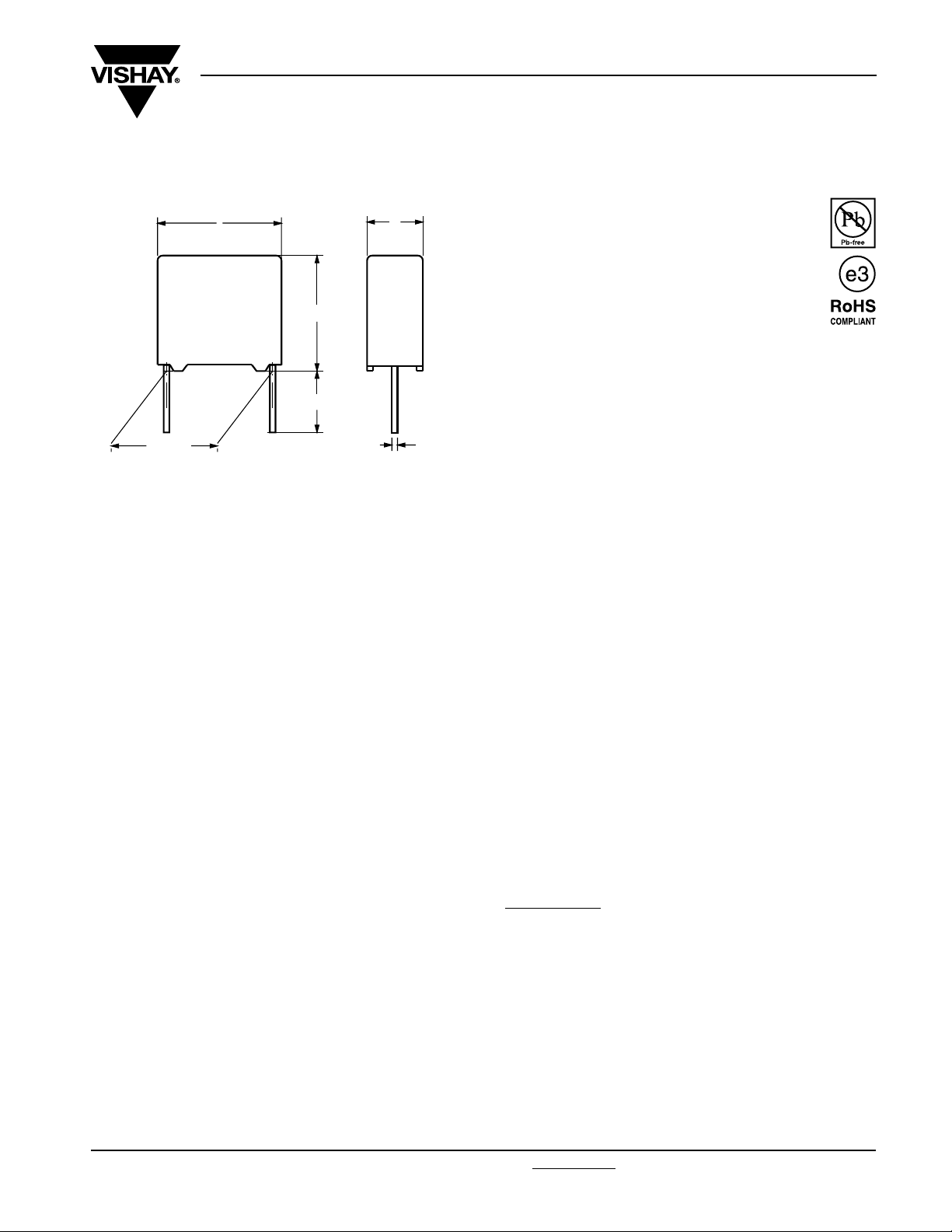
P ± 0.4
Dimensions in mm
l
h
l
t
w
Ø d
t
NO FOCUS PRODUCT: USE MKP 338 6 Y2
APPLICATIONS
Y2 class
For Y2 electromagnetic interference suppression between
line and ground applications (50/60 Hz) with a maximum
mains voltage of 300 Vac.
For application limitations refer to section “Application Notes”
FEATURES
10 mm to 15 mm lead pitch.
Supplied loose in box, taped on reel
Lead (Pb)-free product
RoHS compliant product
PERMISSIBLE DC VOLTAGE
DC 1000 V
ENCAPSULATION
Plastic case, epoxy resin sealed, flame retardant UL-class
94 V-0
CLIMATIC TESTING CLASS ACC. TO EN 60068-1
55/105/56/B
CAPACITANCE RANGE (E12 SERIES)
E12 series 0.001 µF to 0.047 µF
Preferred values acc. to E6
REFERENCE STANDARDS
“IEC 60384-14 2nd edition and EN 132400”
“IEC 60065 requires, pass. flamm. class B”
250 V: UL 1414; CSA-C22.2 No 1;
300 V: UL1283; ENEC
MARKING
C-value; tolerance; rated voltage; sub-class; manufacturer’s
type designation; code for dielectric material; manufacturer
location; year and week
DIELECTRIC
Polypropylene film
ELECTRODES
Metallized film
CONSTRUCTION
Series and triple construction
RATED VOLTAGE
AC 300 V; 50 Hz to 60 Hz
CAPACITANCE TOLERANCE
± 20 %; ± 10 %
LEADS
Tinned wire
MAXIMUM APPLICATION TEMPERATURE
105 °C
DETAIL SPECIFICATION
For more detailed data and test requirements contact:
rfi@vishay.com
Document Number: 28115 For technical questions, contact: rfi@vishay.com
Revision: 23-Dec-08 171
www.vishay.com
MKP 336 6 Y2
Vishay BCcomponents
Interference Suppression Film Capacitors
MKP Radial Potted Type
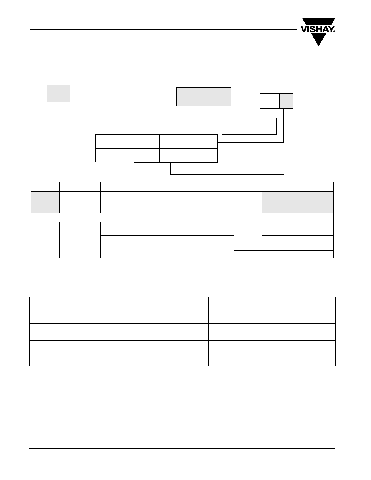
COMPOSITION OF CATALOG NUMBER
TYPE AND PITCHES
336 6
Y2
10.0 mm
15.0 mm
CAPACITANCE
(numerically)
Example:
103 = 10 x 1 = 10 nF
MULTIPLIER
(nF)
0.1
2
1
3
BFC2 336 6X XX X
2222
(*) Old ordering code
TYPE PACKAGING LEAD CONFIGURATION C-TOL PREFERRED TYPES
336 6
Y2
336 6
Y2
Note:
(1) For detailed tape specification refer to Packaging information: www.vishay.com/docs/28139/packinfo.pdf
loose in box
loose in box
taped on reel
lead length 3.5 + 1/- 0.5 mm (pitch = 10 mm) or
3.5 ± 0.3 mm (pitch = 15 mm)
lead length 25.0 ± 2.0 mm
lead length 3.5 + 1/- 0.5 mm (pitch = 10 mm) or
3.5 ± 0.3 mm (pitch = 15 mm)
lead length 25.0 ± 2.0 mm BFC2 336 67...
H = 18.5 mm; P0= 12.7 mm;
(1)
reel diameter 500 mm
(*)
336 6X XX X
± 20 %
± 10 %
± 20 % BFC2 336 63...
± 10 % BFC2 336 64...
BFC2 336 60...
BFC2 336 66...
ON REQUEST
BFC2 336 61...
SPECIFIC REFERENCE DATA MKP 336 6 300 VAC
DESCRIPTION VALUE
Tangent of loss angle:
Rated voltage pulse slope (dU/dt)R at 420 Vdc
R between leads, for C ≤ 0.33 µF at 100 V; 1 minute
R between leads and case; 100 V; 1 minute
Withstanding (DC) voltage (cut off current 10 mA); rise time 100 V/s
Withstanding (AC) voltage between leads and case
www.vishay.com For technical questions, contact: rfi@vishay.com
172 Revision: 23-Dec-08
at 10 kHz
≤ 10 x 10
> 15 000 MΩ
> 30 000 MΩ
3400 V; 1 minute
2100 V; 1 minute
- 4
200 V/µs
Document Number: 28115
MKP 336 6 Y2
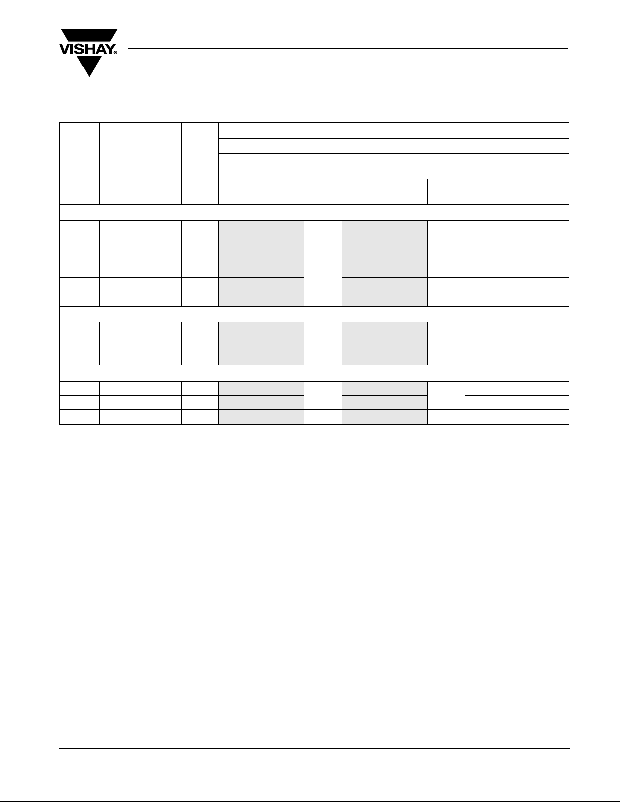
MKP 336 6 GENERAL DATA
U
= 300 V; C-tol = ± 20 %
Rac
C
(µF)
Pitch = 10.0 ± 0.4 mm; d
0.001
0.0015
0.0022
0.0033
0.0047
0.0068
Pitch = 15.0 ± 0.4 mm; d
0.0068
0.01
0.015 6.0 x 12.0 x 17.5 1.4
Pitch = 15.0 ± 0.4 mm; d
0.022 7.0 x 13.5 x 17.5 1.8
0.033 8.5 x 15.0 x 17.5 2.4
0.047 10.0 x 16.5 x 17.5 3.0
DIMENSIONS
W xHxL
(mm)
t
4.0 x 10.0 x 12.5 0.6
5.0 x 11.0 x 12.5 0.82
t
5.0 x 11.0 x 17.5 1.0
t
MASS
= 0.6 ± 0.06 mm
=0.6± 0.06 mm
=0.8± 0.08mm
Interference Suppression Film Capacitors
MKP Radial Potted Type
CATALOG NUMBER BFC2 336 6..... AND PACKAGING
LOOSE IN BOX REEL
= 3.5 + 1/- 0.5 mm (10 mm)
L
(g)
(1)
t
or 3.5 ± 03 mm (= 15 mm)
Last 5 digits of
catalog number
60102
60152 66152 63152
60222 66222 63222
60332 66332 63332
60472 66472
60682 66682 63682
69005
60103 66103 63103
60153 66153 63153 900
60223
60333 66333 63333 650
60473 500 66473 450 63473 600
SPQ
1000
1000
750
l
= 25.0 ± 2.0 mm
t
Last 5 digits of
catalog number
66102
69009
66223
Vishay BCcomponents
H = 18.5 mm;
P
= 12.7 mm
0
SPQ
1250
1000
1000
500
Last 5 digits of
catalog number
63102
63472
69006
63223 800
SPQ
1400
1100
1100
Note
(1)
Weight for short lead product only
Document Number: 28115 For technical questions, contact: rfi@vishay.com
Revision: 23-Dec-08 173
www.vishay.com
MKP 336 6 Y2
Vishay BCcomponents
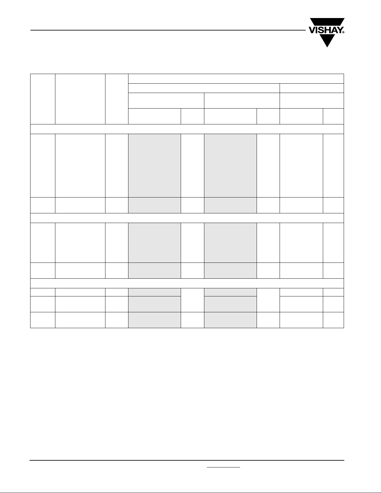
MKP 336 6 GENERAL DATA
U
= 300 V; C-tol = ± 10 %
Rac
C
(µF)
Pitch = 10.0 ± 0.4 mm; d
0.001
0.0012
0.0015
0.0018
0.0022
0.0027
0.0033
0.0039
0.0047
0.0056
Pitch = 15.0 ± 0.4 mm; d
0.0056
0.0068
0.0082
0.01
0.012
0.015
0.018
Pitch = 15.0 ± 0.4 mm; d
0.022 7.0 x 13.5 x 17.5 1.8
0.027
0.033
0.039
0.047
DIMENSIONS
WxHxL
(mm)
t
4.0 x 10.0 x 12.5 0.6
5.0 x 11.0 x 12.5 1.1
t
5.0 x 11.0 x 17.5 1.0
6.0 x 12.0 x 17.5 1.4
t
8.5 x 15.0 x 17.5 2.4
10.0 x 16.5 x 17.5 3.0
MASS
(g)
= 0.6 ± 0.06 mm
= 0.80 ± 0.08 mm
= 0.80 ± 0.08 mm
Interference Suppression Film Capacitors
MKP Radial Potted Type
CATALOG NUMBER BFC2 336 6..... AND PACKAGING
LOOSE IN BOX REEL
= 3.5 + 1/- 0.5 mm (10 mm)
L
t
(1)
or 3.5 ± 03 mm (= 15 mm)
Last 5 digits of
catalog number
61102
61122 67122 64122
61152 67152 64152
61182 67182 64182
61222 67222 64222
61272 67272 64272
61332 67332 64332
61392 67392 64392
61472
61562 67562 64562
69001
61682 67682 64682
61822 67822 64822
61103 67103 64103
61123 67123 64123
61153
61183 67183 64183
61223
61273 67273 64273
61333 67333 64333
61393
61473 67473 64473
SPQ
1000
1000
1000
1000
750
500
l
= 25.0 ± 2.0 mm
t
Last 5 digits of
catalog number
67102
67472
69007
67153
67223
67393
SPQ
1250
1000
1000
1000
500
450
H = 18.5 mm;
P
= 12.7 mm
0
Last 5 digits of
catalog number
64102
64472
69003
61153
64223 800
61393
SPQ
1400
1100
1100
900
650
600
Note
(1)
Weight for short lead product only
www.vishay.com For technical questions, contact: rfi@vishay.com Document Number: 28115
174 Revision: 23-Dec-08

MKP 336 6 Y2
6
Interference Suppression Film Capacitors
Vishay BCcomponents
MKP Radial Potted Type
SAFETY APPROVALS Y2 VOLTAGE VALUE FILE NUMBERS
EN132400 300 Vac 1 nF to 47 nF FI 2006018
UL1414 and CSA-C 22.2 No 1
antenna coupling
UL1283 300 Vac 1 nF to 47 nF E109565
The Enec-approval together with the CB-Certificate replace all national marks of the following countries (they have already signed the
ENEC-Agreement): Austria; Belgium; Czech. Republic; Denmark; Finland; France; Germany; Greece; Hungary; Ireland; Italy; Luxembourg;
Netherlands; Norway; Portugal; Slovenian; Spain; Switzerland and United Kingdom.
MOUNTING
Normal Use
The capacitors are designed for mounting on printed-circuit
boards. The capacitors packed in bandoliers are designed
for mounting in printed-circuit boards by means of automatic
insertion machines.
Specific Method of Mounting to Withstand Vibration and
Shock
In order to withstand vibration and shock tests, it must be
ensured that the stand-off pips are in good contact with the
printed-circuit board:
• The capacitors shall be mechanically fixed by the leads
250 Vac 1 nF to 47 nF E112471
Eccentricity
l
= I + 0.3 mm
max.
Storage Temperature
• Storage temperature: T
= - 25 °C to + 40 °C with RH
stg
maximum 80 % without condensation
b
= b + 0.3 mm
max.
CBA11
Space Requirements on printed Circuit Board
The maximum length and width of film capacitors is shown in
Figure:
• Eccentricity as in figure. The maximum eccentricity is
smaller than or equal to the lead diameter of the product
concerned
• Product height with seating plane as given by “IEC 60717”
as reference: h
≤ h + 0.3 mm
max.
Ratings and Characteristics Reference Conditions
Unless otherwise specified, all electrical values apply to an
ambient temperature of 23 °C ± 1 °C, an atmospheric
pressure of 86 kPa to 106 kPa and a relative humidity of
50 % ± 2 %.
For reference testing, a conditioning period shall be applied
over 96 hours ± 4 hours by heating the products in a
circulating air oven at the rated temperature and a relative
humidity not exceeding 20 %.
Document Number: 28115 For technical questions, contact: rfi@vishay.com
Revision: 23-Dec-08 175
www.vishay.com

MKP 336 6 Y2
Vishay BCcomponents
CHARACTERISTICS
Capacitance
4
ΔC/C
(%)
2
typical
0
- 2
- 4
- 6
- 50
Impedance
3
10
Impedance
(Ω)
101
100
0 50 100Ta mb (°C)
1 nF
4.7 nF
10 nF
47 nF
Interference Suppression Film Capacitors
MKP Radial Potted Type
Tangent of loss angle
3
10
)
- 4
Dissipation
Factor (x 10
2
10
1
10
min.
0
10
1
Resonant frequency
2
10
f (MHz)
1
10
2 3 4
10 nF < C ≤ 47 nF
10 nF
≤
C
5
10 10 101010
f (Hz)
10-1
-
2
10
4
10
5
10
6
10
10
Max RMS voltage and AC current (sinewave)
3
10
AC voltage
(V)
2
10
T
≤ 105 °C
amb
1
10
1
10
2
10
3
10
10
0
7
4
f (Hz)
f (Hz)
8
10
5
10
10
10
AC current
10
10
10
1
3
(mA)
1
0
-1
10
≤ 105 °C
4
47 nF
10 nF
4.7 nF
1nF
f (Hz)
C (nF)
10
5
10 47
T
amb
1
2
10
3
10
10
www.vishay.com For technical questions, contact: rfi@vishay.com Document Number: 28115
176 Revision: 23-Dec-08

MKP 336 6 Y2
Interference Suppression Film Capacitors
Vishay BCcomponents
MKP Radial Potted Type
Insulation resistance
6
10
RC (s)
5
10
4
10
0
20 40 60
APPLICATION NOTES
• For Y2 electromagnetic interference suppression between line and ground (50/60 Hz) with a maximum mains voltage of
300 Vac ± 10 % instability.
• These capacitors are not intended for continuous pulse applications. For these situations, capacitors of the AC and pulse
program must be used.
• The maximum ambient temperature must not exceed 105 °C.
• Rated voltage pulse slope:
If the pulse voltage is lower than the rated voltage, the values of the specific reference data can be multiplied by 420 Vdc and
divided by the applied voltage.
80
100
(°C)
T
amb
Document Number: 28115 For technical questions, contact: rfi@vishay.com
Revision: 23-Dec-08 177
www.vishay.com

MKP 336 6 Y2
Vishay BCcomponents
Interference Suppression Film Capacitors
MKP Radial Potted Type
INSPECTION REQUIREMENTS
General Notes:
1. Sub-clause numbers of tests and performance requirements refer to the “ Sectional Specification, IEC-puplication EN 132400
(IEC 60384-14) and section One of this specification”.
2. In this table: D = destructive
ND = non destructive
Group C inspection requirements
SUB - CLAUSE NUMBER
AND TEST
Group C inspection (periodic) see section “General notes“ item 3
SUB-GROUP C1A PART OF SAMPLE
OF SUB-GROUP C1
4.1 Dimensions (detail) As specified in Chapters “General data”
Initial measurements Capacitance
4.3 Robustness of
terminations
4.4 Resistance to soldering heat No pre-drying
4.19 Component solvent
resistance
4.4.2 Final measurements Visual examination No visible damage
SUB - GROUP C1B PART OF SAMPLE
OF SUB - GROUP C1
Initial measurements Capacitance
4.20 Solvent resistance of the marking:
see Section “General notes”; item 5
4.6 Rapid change of temperature θA = - 55 °C
4.6.1 Inspection Duration t = 30 minutes
D
OR
ND
D
Tangent of loss angle at 10 kHz
Tensile: load 10 N; 10 secondsBending:
load 5 N; 4 x 90°
Method: 1A
Solder bath: 260 °C
Duration: 10 seconds
Isopropylalcohol at room temperature
Method: 2
Immersion time: 5 ± 0.5 minutes
Recovery time:
Min. 1 hour, max. 2 hours
Capacitance |ΔC/C| ≤ 5 % of the value measured
Tangent of loss angle Increase of tan δ:
Insulation resistance As specified in Section “Insulation
D
Tangent of loss angle at 10 kHz
Isopropylalcohol at room temperature
Method: 1
Rubbing material: cotton wool
Immersion time: 5 ± 0.5 minutes
θB = + 105 °C
5 cycles
CONDITIONS PERFORMANCE REQUIREMENTS
of this specification
No visible damage
Legible marking
initially
≤ 0.008
Compared to values measured initially
Resistance” of this specification
No visible damage
Legible marking
www.vishay.com For technical questions, contact: rfi@vishay.com Document Number: 28115
178 Revision: 23-Dec-08

MKP 336 6 Y2
Interference Suppression Film Capacitors
Vishay BCcomponents
MKP Radial Potted Type
SUB - CLAUSE NUMBER
AND TEST
4.7 Vibration (see note 3) Visual examination
4.7.2 Final inspection Visual examination No visible damage
4.9 Shock (see note 3) Mounting: see Section “Mounting” for
4.9.2 Final measurements Visual examination No visible damage
SUB - GROUP C1 COMBINED
SAMPLE OF SPECIMENS OF
SUB - GROUPS C1A AND C1B
4.11 Climatic sequence
4.11.1 Initial measurements Capacitance
4.11.2 Dry heat Temperature: 105 °C
4.11.3 Damp heat cyclic
Tes t Db
First cycle
4.11.4 Cold Temperature: - 55 °C
4.11.5 Damp heat cyclic
Test Db
remaining cycles
4.11.6 Final measurements Visual examination No visible damage
D
OR
ND
Mounting: see Section “Mounting” of this
specification
Procedure B4
Frequency range: 10 Hz to 55 Hz.
Amplitude: 0.75 mm or
Acceleration 98 m/s²
(whichever is less severe)
Total duration 6 hours.
more information
Pulse shape: half sine
Acceleration: 490 m/s²
Duration of pulse: 11 ms.
Capacitance |ΔC/C| ≤ 5 % of the value measured
Tangent of loss angle Increase of tan δ:
Insulation resistance As specified in Section “Insulation
D
Measured in 4.4.2 and 4.9.2
Tangent of loss angle:
Measured initially in C1A and C1B
Duration: 16 hours
Duration: 2 hours
CONDITIONS PERFORMANCE REQUIREMENTS
No visible damage
initially
≤ 0.008
Compared to values measured
initially
Resistance” of this specification
Legible marking
Capacitance |ΔC/C| ≤ 5 % of the value measured in
Tangent of loss angle Increase of tan δ:
Voltage proof
2250 Vdc; 1 minute between term.
Insulation resistance ≥ 50 % of values specified in Section
Document Number: 28115 For technical questions, contact: rfi@vishay.com
Revision: 23-Dec-08 179
4.11.1.
≤ 0.008
Compared to values measured in
4.11.1.
No permanent breakdown or flash-over
“Insulation resistance” of this
specification
www.vishay.com

MKP 336 6 Y2
Vishay BCcomponents
Interference Suppression Film Capacitors
MKP Radial Potted Type
SUB - CLAUSE NUMBER
AND TEST
SUB - GROUP C2 D
4.12 Damp heat steady state 56 days, 40 °C, 90 to 95 % RH no load
4.12.1 Initial measurements Capacitance
4.12.3 Final measurements Visual examination No visible damage
D
OR
ND
capacitance
Tangent of loss angle at 10 kHz
Capacitance |ΔC/C| ≤ 5 % of the value measured in
Tangent of loss angle Increase of tan δ:
Voltage proof
2250 Vdc; 1 minute between term.
CONDITIONS PERFORMANCE REQUIREMENTS
Legible marking
4.12.1.
≤ 0.007
Compared to values measured in
4.12.1.
No permanent breakdown or flash-over
Insulation resistance ≥ 50 % of values specified in Section
SUB- GROUP C3 D
4.13.1 Initial measurements Capacitance
4.13 Impulse voltage 3 successive impulses, full wave, peak
4.14 Endurance Duration: 1000 hours
4.14.7 Final measurements Visual examination No visible damage
Tangent of loss angle at 10 kHz
voltage:
5 kV
Max. 24 pulses
1.7 U
at 105 °C
Rac
Once in every hour the voltage is
increased to 1000 V (RMS) for 0.1 s via
resistor of 47 Ω ± 5 %
Capacitance |ΔC/C| ≤ 10 % compared to values
Tangent of loss angle Increase of tan δ:
Voltage proof
2250 Vdc;
1 minute between terminations
“Insulation resistance” of this
specification
No selfhealing breakdowns or flashover
Legible marking
measured in 4.13.1.
≤ 0.007
Compared to values measured in
No permanent breakdown or flash-over
Insulation resistance ≥ 50 % of values specified in Section
www.vishay.com For technical questions, contact: rfi@vishay.com Document Number: 28115
180 Revision: 23-Dec-08
“Insulation resistance” of this
specification

MKP 336 6 Y2
Interference Suppression Film Capacitors
MKP Radial Potted Type
SUB - CLAUSE NUMBER
AND TEST
SUB - GROUP C 4 D
4.15 Charge and discharge 10 000 cycles
4.15.1 Initial measurements Capacitance
4.15.3 Final measurements Capacitance |ΔC/C| ≤ 10 % compared to values
SUB - GROUP C5 D
4.16 Radio frequency characteristic Resonance frequency As specified in Section “Resonant
SUB - GROUP C6 D
4.17 Passive flammability
Class B
D
OR
ND
(50 c/s) charge to U
Duration: 5 ms
Discharge resistance:
R
=
R
min.
Tangent of loss angle at 10 kHz
Tangent of loss angle Increase of tan δ:
Insulation resistance ≥ 50 % of values specified in Section
Bore of gas jet: Ø 0.5 mm
Fuel: butane
Test duration for actual volume V in mm³:
V ≤ 250: 10 seconds
250 < V ≤ 500: 20 seconds
500 < V ≤ 1750: 30 seconds
V > 1750: 60 seconds
One flame application
CONDITIONS PERFORMANCE REQUIREMENTS
half sinewave
R
420 Vdc
---------------------------------------------------
1.5 C dU()dt()⁄()×
= 2.2 Ω
measured in 4.15.1.
≤ 0.008
Compared to values measured in
4.15.1.
“Insulation resistance” of this
specification
frequency” of this specification. ± 10 %
After removing test flame from capacitor,
the capacitor must not continue to burn
for more than 10 seconds. No burning
particle must drop from the sample.
BCcomponents
Vishay
12 mm
~ 8 mm
45.0°
SUB - GROUP C7 D
4.18 Active flammability 20 x 5 kV discharges on the test
Document Number: 28115 For technical questions, contact: rfi@vishay.com
Revision: 23-Dec-08 181
capacitor connected to U
R
The cheese cloth around the capacitors
shall not burn with a flame.
No electrical measurements are
required.
www.vishay.com

Legal Disclaimer Notice
Vishay
Disclaimer
All product specifications and data are subject to change without notice.
Vishay Intertechnology, Inc., its affiliates, agents, and employees, and all persons acting on its or their behalf
(collectively, “Vishay”), disclaim any and all liability for any errors, inaccuracies or incompleteness contained herein
or in any other disclosure relating to any product.
Vishay disclaims any and all liability arising out of the use or application of any product described herein or of any
information provided herein to the maximum extent permitted by law. The product specifications do not expand or
otherwise modify Vishay’s terms and conditions of purchase, including but not limited to the warranty expressed
therein, which apply to these products.
No license, express or implied, by estoppel or otherwise, to any intellectual property rights is granted by this
document or by any conduct of Vishay.
The products shown herein are not designed for use in medical, life-saving, or life-sustaining applications unless
otherwise expressly indicated. Customers using or selling Vishay products not expressly indicated for use in such
applications do so entirely at their own risk and agree to fully indemnify Vishay for any damages arising or resulting
from such use or sale. Please contact authorized Vishay personnel to obtain written terms and conditions regarding
products designed for such applications.
Product names and markings noted herein may be trademarks of their respective owners.
Document Number: 91000 www.vishay.com
Revision: 18-Jul-08 1
 Loading...