

MKP 1848 DC-Link
Vishay Roederstein
Metallized Polypropylene Film Capacitors
DC Capacitor MKP Type
FEATURES
WI
h
Lead (Pb)-free product
RoHS compliant product
RATED CAPACITANCE
1 µF to 400 µF
CAPACITANCE TOLERANCE
± 5 %
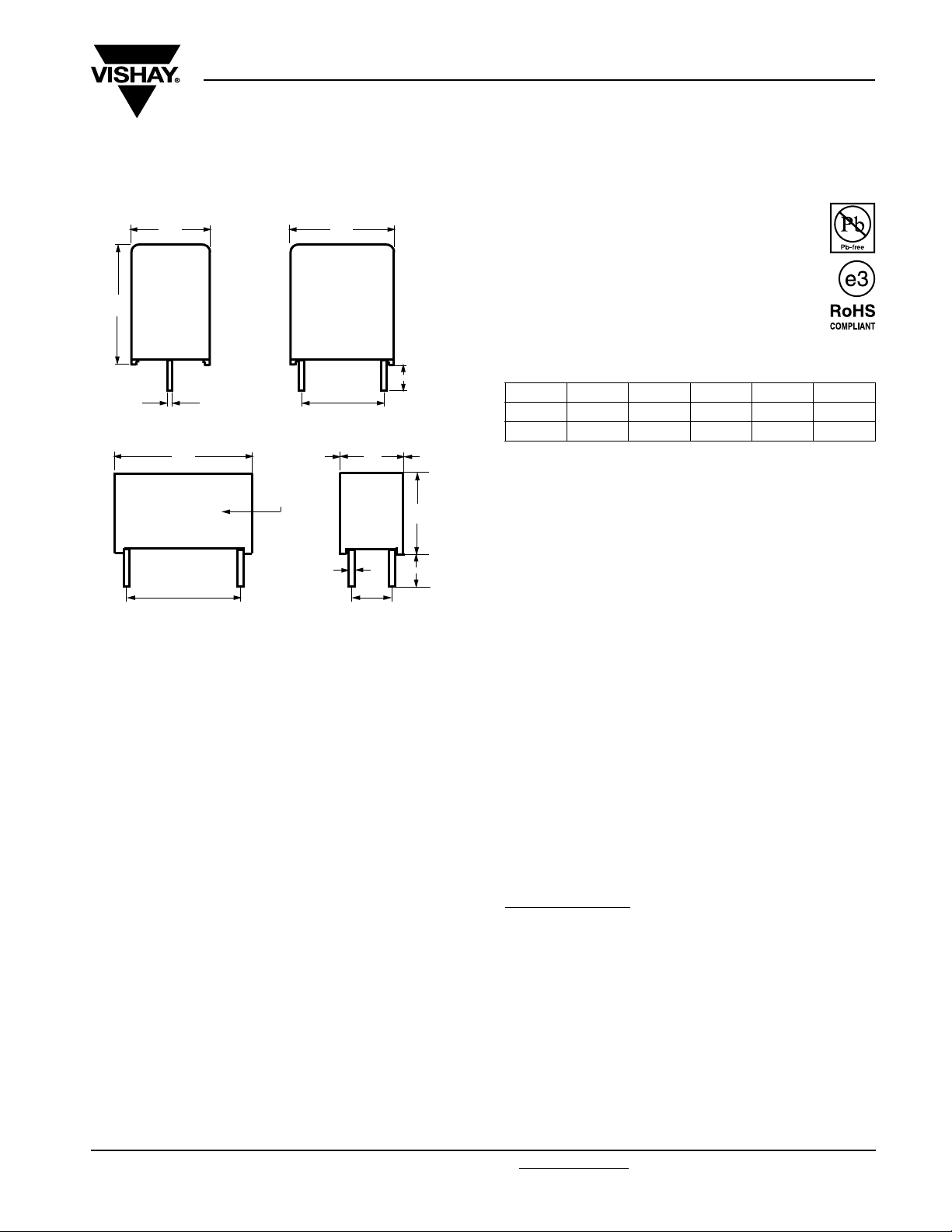
6 - 1
Ø d
t
I
P1 ± 0.5 P2 ± 0.5
Dimensions in millimeters
Ø d
± 10 % of standard diameter specified
t
P1 ± 0.4 - PCM 27.5 mm
P1 ± 0.5 - PCM ≥ 37.5 mm
Marking
Ø d
t
W
h
6 - 2
APPLICATIONS
High performance DC filtering applications
REFERENCE STANDARDS
IEC 61071
IEC 60068
MARKING
C-value; tolerance; rated voltage; code for dielectric
material; code for manufacturing origin; manufacturer’s type
designation; manufacturer’s logo; year and week of
manufacture
DIELECTRIC
Polypropylene film
DC VOLTAGE RATING
85 °C 450 V 700 V 900 V 1100 V 1200 V
70 °C 500 V 800 V 1100 V 1350 V 1500 V
105 °C 300 V 500 V 650 V 800 V 850 V
INSULATION RESISTANCE
RC between leads, after 1 min > 10 000 s
For U
For U
≤ 500 V measuring voltage 100 V
Ndc
> 500 V measuring voltage 500 V
Ndc
SELF INDUCTANCE (Ls)
< 1 nH per mm of lead spacing
TEST VOLTAGE BETWEEN TERMINALS
1.5 U
for 10 s
Ndc
CLIMATIC TESTING CLASS
40/85/56
MAXIMUM APPLICATION TEMPERATURE
85 °C
MAXIMUM OPERATING TEMPERATURE (CASE)
105 °C
LIFETIME EXPECTANCY
Operation life time > 100 000 h
FIT: < 10 x 10
40 °C
-9
/h (10 per 109 component h) at 0.5 x U
Ndc
DETAIL SPECIFICATION
For more detailed data and test requirements, contact:
dc-film@vishay.com
;
ELECTRODES
Metallized dielectric capacitor
CONSTRUCTION
Mono construction
ENCAPSULATION
Plastic case, sealed with resin
Flame retardant
TERMINALS
Tinned wires
Document Number: 28164 For technical questions, contact: dc-film@vishay.com
Revision: 02-Feb-09 281
www.vishay.com
MKP 1848 DC-Link
Vishay Roederstein
Metallized Polypropylene Film Capacitors
DC Capacitor MKP Type
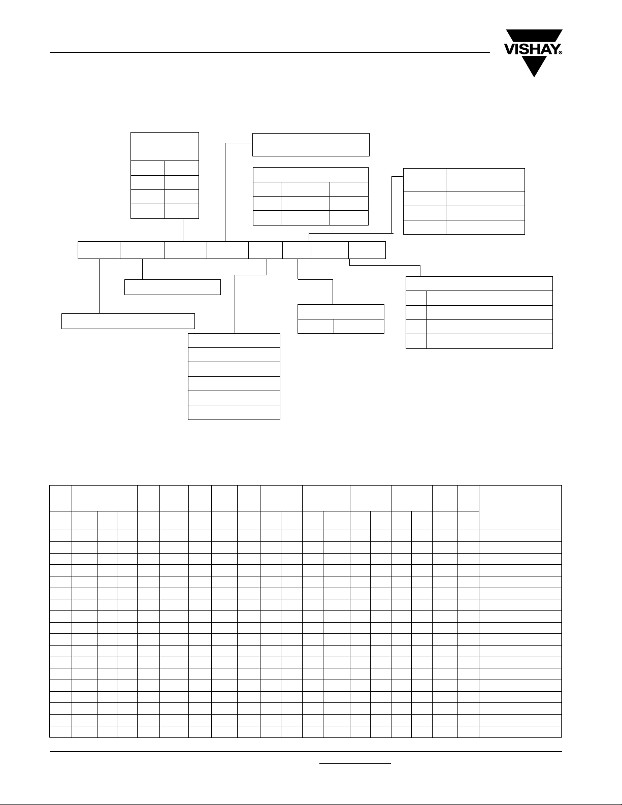
COMPOSITION OF CATALOG NUMBER
MULTIPLIER
(nF)
10 4
100 5
1000 6
10 000 7
512 1200 nF 1.2 µF
612 12 000 nF 12 µF
712 120 000 nF 120 µF
MKP 1848 6 12 09 4 P 4
TYPE CONSTRUCTION
METALLIZED POLYPROPYLENE
VOLTAG E
U
= 45 = 450 V
n
U
= 70 = 700 V
n
= 09 = 900 V
U
n
U
= 91 = 1100 V
n
U
= 92 = 1200 V
n
Note
(1)
Tabs terminals or customized terminals are available on request
CAPACITANCE
(numerically)
Example:
TOLERANCE
4± 5 %
P1
(mm)
PITCH
CODE
27.5 K
37.5 P
52.5 Y
SPECIAL CODE FOR TERMINAL
2 2 pins
4
4 pins P2 = 10.2 mm
5 4 pins P2 = 20.3 mm
(1)
Customized
SPECIFIC REFERENCE DATA 450 Vdc
U
= 450 V, U
Ndc
CAP.
DIMENSIONS
(5)
(mm)
(µF) W H L (mm) (mm) (mm) (V/µs) (A)
1 9.0 19.0 32.0 27.5 - 0.8 75 75 1.5 - 115 - 11.0 - 100 - 6.8 160 MKP1848510454K2
2 9.0 19.0 32.0 27.5 - 0.8 75 150 2.5 - 57.5 - 11.0 - 100 - 6.0 160 MKP1848520454K2
3 11.0 21.0 32.0 27.5 - 0.8 75 225 3.0 - 38.5 - 11.0 - 100 - 9.2 130 MKP1848530454K2
4 11.0 21.0 32.0 27.5 - 0.8 75 300 3.5 - 30.0 - 11.0 - 100 - 8.4 130 MKP1848540454K2
5 13.0 23.0 32.0 27.5 - 0.8 75 375 4.0 - 23.0 - 11.0 - 100 - 10.7 115 MKP1848550454K2
6 15.0 25.0 32.0 27.5 - 0.8 75 450 4.5 - 19.0 - 11.0 - 100 - 12.5 100 MKP1848560454K2
7 15.0 25.0 32.0 27.5 - 0.8 75 525 5.0 - 16.5 - 11.0 - 100 - 11.7 100 MKP1848570454K2
8 18.0 28.0 32.0 27.5 - 0.8 75 600 6.0 - 14.0 - 11.0 - 100 - 17.2 80 MKP1848580454K2
9 18.0 28.0 32.0 27.5 - 0.8 75 675 6.5 - 13.0 - 11.0 - 100 - 16.3 80 MKP1848590454K2
10 18.0 28.0 32.0 27.5 - 0.8 75 750 7.0 - 11.5 - 11.0 - 100 - 15.4 80 MKP1848610454K2
12 21.0 31.0 32.0 27.5 - 0.8 75 900 8.0 - 10.0 - 11.0 - 100 - 22.2 65 MKP1848612454K2
10 18.5 35.5 43.0 37.5 10.2 1.0 40 400 6.0 6.5 23.0 20.5 22.0 20.0 200 185 37.5 105 MKP1848610454P*
12 18.5 35.5 43.0 37.5 10.2 1.0 40 480 7.0 7.5 19.0 17.0 22.0 20.0 200 185 36.1 105 MKP1848612454P*
15 18.5 35.5 43.0 37.5 10.2 1.0 40 600 7.5 8.0 15.0 13.0 22.0 20.0 200 185 33.9 105 MKP1848615454P*
20 21.5 38.5 43.0 37.5 10.2 1.0 40 800 9.0 10 11.5 13.5 22.0 20.0 200 185 41.6 91 MKP1848620454P*
22 21.5 38.5 43.0 37.5 10.2 1.0 40 880 9.5 10.0 10.5 9.5 22.0 20.0 200 185 40.1 91 MKP1848622454P*
25 21.5 38.5 43.0 37.5 10.2 1.0 40 1000 10.0 10.5 9.5 8.5 22.0 20.0 200 185 37.8 91 MKP1848625454P*
30 24.0 44.0 42.0 37.5 10.2 1.0 40 1200 11.0 12.0 7.5 8.0 22.0 20.0 200 185 50 77 MKP1848630454P*
www.vishay.com For technical questions, contact: dc-film@vishay.com
282 Revision: 02-Feb-09
Ndc70 °C
(4)
= 500 V, U
P1 P2
Ndc105 °C
Ø d
= 300 V
dV/dtI
t
I
PEAK
RMS
(2)
(A)
2
pins4pins2 pins4pins2 pins4pins2 pins4pins
ESR
(mΩ)
tan δ
1 kHz
(3)
< (10
-4
)
tan δ
10 kHz
< (10-4)
MASS SPQ
(g) (pcs)
Document Number: 28164
PART NUMBER
(1)
MKP 1848 DC-Link
Metallized Polypropylene Film Capacitors
Vishay Roederstein
DC Capacitor MKP Type
CAP.
DIMENSIONS
(5)
(mm)
P1 P2
(4)
Ø d
t
dV/dt
I
PEAK
(µF) W H L (mm) (mm) (mm) (V/µs) (A)
35 30.0 45.0 42.0 37.5
40 30.0 45.0 42.0 37.5
10.2 /
1.0 40 1400 14.0 15.0 6.5 5.9 22.0 20.0 200 185 67 63 MKP1848635454P*
20.3
10.2 /
1.0 40 1600 14.5 15.5 6.0 5.0 22.0 20.0 200 185 63 63 MKP1848640454P*
20.3
I
RMS
(2)
(A)
2
pins4pins2 pins4pins2 pins4pins2 pins4pins
ESR
(mΩ)
tan δ
1 kHz
(3)
< (10
40 25.0 45.0 57.5 52.5 20.3 1.2 20 800 11.0 12.0 11.5 10.0 40.0 36.0 400 370 77 55 MKP1848640454Y*
45 25.0 45.0 57.5 52.5 20.3 1.2 20 900 12.0 13.0 10.0 9.0 40.0 36.0 400 370 73 55 MKP1848645454Y*
50 30.0 45.0 57.5 52.5 20.3 1.2 20 1000 13.0 14.0 9.0 8.5 40.0 36.0 400 370 104 45 MKP1848650454Y*
55 30.0 45.0 57.5 52.5 20.3 1.2 20 1100 14.0 15.0 8.5 7.5 40.0 36.0 400 370 100 45 MKP1848655454Y*
60 30.0 45.0 57.5 52.5 20.3 1.2 20 1200 14.5 15.5 7.5 6.5 40.0 36.0 400 370 95 45 MKP1848660454Y*
65 35.0 50.0 57.5 52.5 20.3 1.2 20 1300 16.0 17.0 7.0 6.0 40.0 36.0 400 370 119 40 MKP1848665454Y*
70 35.0 50.0 57.5 52.5 20.3 1.2 20 1400 17.0 18.0 6.5 6.0 40.0 36.0 400 370 117 40 MKP1848670454Y*
75 35.0 50.0 57.5 52.5 20.3 1.2 20 1500 17.5 18.5 6.0 5.5 40.0 36.0 400 370 113 40 MKP1848675454Y*
80 35.0 50.0 57.5 52.5 20.3 1.2 20 1600 18.0 19.0 5.5 5.0 40.0 36.0 400 370 106 40 MKP1848680454Y*
90 45.0 45.0 57.5 52.5 20.3 1.2 20 1800 - 15.5 - 4.5 - 36.0 - 370 192 30 MKP1848690454Y5
95 45.0 45.0 57.5 52.5 20.3 1.2 20 1900 - 15.5 - 4.0 - 36.0 - 370 192 30 MKP1848695454Y5
100 45.0 45.0 57.5 52.5 20.3 1.2 20 2000 - 16.0 - 4.0 - 36.0 - 370 192 30 MKP1848710454Y5
200 70.0 60.0 57.5 52.5 20.3 1.2 20 2000 - 38.0 - 2.0 - 36.0 - 370 451 20 MKP1848720454Y5
400 130.0 60.0 57.5 52.5 20.3 1.2 10 4000 - 68.0 - 1.0 - 36.0 - 370 946 10 MKP1848740454Y5
Notes
(1)
Change the * symbol with special code for the terminals
(2)
Maximum rms current at 10 kHz, + 85 °C, Cap. tol. ≤ ± 5 %
(3)
Equivalent series resistance typical values at 10 kHz
(4)
Standard dimension
(5)
Intermediate capacitance values available on request.
• SPQ = Standard Packing Quantity
tan δ
10 kHz
-4
)
< (10-4)
MASS SPQ
PART NUMBER
(g) (pcs)
(1)
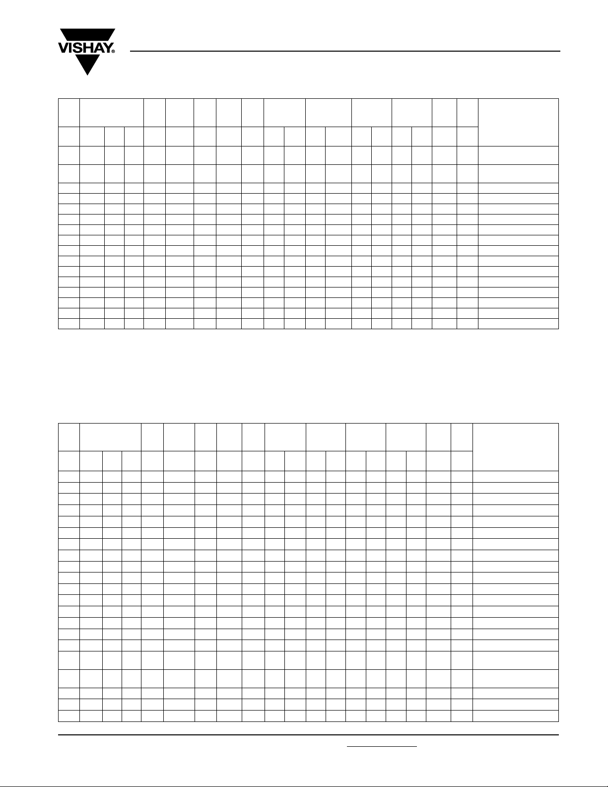
SPECIFIC REFERENCE DATA 700 Vdc
U
= 700 V, U
Ndc
CAP.
DIMENSIONS
(5)
(mm)
(µF) W H L (mm)(mm)(mm)(V/µs)(A)
1 9.0 19.0 32.0 27.5 - 0.8 65 65 1.5 - 94.0 - 10.0 - 85 - 6.6 160 MKP1848510704K2
2 9.0 19.0 32.0 27.5 - 0.8 65 130 2.5 - 47.0 - 10.0 - 85 - 5.6 160 MKP1848520704K2
3 11.0 21.0 32.0 27.5 - 0.8 65 195 3.0 - 31.5 - 10.0 - 85 - 8.5 130 MKP1848530704K2
4 13.0 23.0 32.0 27.5 - 0.8 65 260 4.0 - 23.5 - 10.0 - 85 - 10.5 115 MKP1848540704K2
5 15.0 25.0 32.0 27.5 - 0.8 65 325 4.5 - 19.0 - 10.0 - 85 - 12.1 100 MKP1848550704K2
6 18.0 28.0 32.0 27.5 - 0.8 65 390 6.0 - 16.0 - 10.0 - 85 - 17.4 80 MKP1848560704K2
7 18.0 28.0 32.0 27.5 - 0.8 65 455 6.5 - 13.5 - 10.0 - 85 - 16.2 80 MKP1848570704K2
8 18.0 28.0 32.0 27.5 - 0.8 65 520 7.0 - 12.0 - 10.0 - 85 - 15.1 80 MKP1848580704K2
9 21.0 31.0 32.0 27.5 - 0.8 65 585 7.5 - 10.5 - 10.0 - 85 - 22.5 65 MKP1848590704K2
10 21.0 31.0 32.0 27.5 - 0.8 65 650 8.5 - 9.5 - 10.0 - 85 - 21.3 65 MKP1848610704K2
10 18.5 35.5 43.0 37.5 10.2 1.0 30 300 7.0 7.5 19.5 17.5 19.0 17.0 170 160 35.5 105 MKP1848610704P*
12 18.5 35.5 43.0 37.5 10.2 1.0 30 360 7.5 8.0 16.5 15.0 19.0 17.0 170 160 33.7 105 MKP1848612704P*
15 18.5 35.5 43.0 37.5 10.2 1.0 30 450 8.0 9.0 13.0 11.5 19.0 17.0 170 160 30.8 105 MKP1848615704P*
20 21.5 38.5 43.0 37.5 10.2 1.0 30 600 10.0 11.0 10.0 9.0 19.0 17.0 170 160 37.3 91 MKP1848620704P*
22 24.0 44.0 42.0 37.5 10.2 1.0 30 660 11.0 12.0 9.0 8.0 19.0 17.0 170 160 51 77 MKP1848622704P*
25 24.0 44.0 42.0 37.5 10.2 1.0 30 750 12.0 13.0 8.0 7.0 19.0 17.0 170 160 48 77 MKP1848625704P*
30 30.0 45.0 42.0 37.5
35 30.0 45.0 42.0 37.5
30 25.0 45.0 57.5 52.5 20.3 1.2 15 450 10.5 11.5 13.0 11.5 35.0 33.0 350 320 78 55 MKP1848630704Y*
35 25.0 45.0 57.5 52.5 20.3 1.2 15 525 11.5 12.0 11.0 10.0 35.0 33.0 350 320 73 55 MKP1848635704Y*
40 25.0 45.0 57.5 52.5 20.3 1.2 15 600 12.0 12.5 10.0 9.0 35.0 33.0 350 320 68 55 MKP1848640704Y*
Document Number: 28164 For technical questions, contact: dc-film@vishay.com
Revision: 02-Feb-09 283
Ndc70 °C
(4)
= 800 V, U
P1 P2
10.2 /
10.2 /
= 500 V
Ndc105 °C
I
Ø d
dV/dtI
t
1.0 30 900 14.0 14.5 6.5 6.0 19.0 17.0 170 160 64 63 MKP1848630704P*
20.3
1.0 30 1050 15.0 15.5 5.5 5.0 19.0 17.0 170 160 58 63 MKP1848635704P*
20.3
PEAK
RMS
(A)
2
pins4pins2 pins4pins2 pins4pins2 pins4pins
ESR
(2)
(mΩ)
tan δ
1 kHz
(3)
< (10
tan δ
10 kHz
-4
)
< (10-4)
MASS SPQ
PART NUMBER
(g) (pcs)
(1)
www.vishay.com
MKP 1848 DC-Link
Vishay Roederstein
Metallized Polypropylene Film Capacitors
DC Capacitor MKP Type
CAP.
DIMENSIONS
(5)
(mm)
P1 P2
(4)
Ø d
dV/dtI
t
PEAK
(µF) W H L (mm) (mm) (mm) (V/µs) (A)
I
RMS
(A)
2
pins4pins2 pins4pins2 pins4pins2 pins4pins
ESR
(2)
(mΩ)
tan δ
1 kHz
(3)
< (10
45 30.0 45.0 57.5 52.5 20.3 1.2 15 675 13.5 14.5 9.0 7.5 35.0 33.0 350 320 99 45 MKP1848645704Y*
50 30.0 45.0 57.5 52.5 20.3 1.2 15 750 14.5 15.5 8.0 7.0 35.0 33.0 350 320 92 45 MKP1848650704Y*
55 35.0 50.0 57.5 52.5 20.3 1.2 15 825 16.0 17.0 7.0 6.5 35.0 33.0 350 320 117 40 MKP1848655704Y*
60 35.0 50.0 57.5 52.5 20.3 1.2 15 900 17.0 18.0 6.5 6.0 35.0 33.0 350 320 112 40 MKP1848660704Y*
65 35.0 50.0 57.5 52.5 20.3 1.2 15 975 17.5 18.5 6.0 5.5 35.0 33.0 350 320 104 40 MKP1848665704Y*
70 45.0 45.0 57.5 52.5 20.3 1.2 15 1050 - 20.0 - 5.0 - 33.0 - 320 192 30 MKP1848670704Y5
75 45.0 45.0 57.5 52.5 20.3 1.2 15 1125 - 21.0 - 4.5 - 33.0 - 320 192 30 MKP1848675704Y5
80 45.0 45.0 57.5 52.5 20.3 1.2 15 1200 - 21.5 - 4.5 - 33.0 - 320 192 30 MKP1848680704Y5
160 70.0 60.0 57.5 52.5 20.3 1.2 15 2400 - 38.0 - 2.2 - 33.0 - 320 451 20 MKP1848716704Y5
320 130.0 60.0 57.5 52.5 20.3 1.2 15 4800 - 65.0 - 1.0 - 33.0 - 320 821 10 MKP1848732704Y5
Notes
(1)
Change the * symbol with special code for the terminals
(2)
Maximum rms current at 10 kHz, + 85 °C, Cap. tol. ≤ ± 5 %
(3)
Equivalent series resistance typical values at 10 kHz
(4)
Standard dimension
(5)
Intermediate capacitance values are available on request.
• SPQ = Standard Packing Quantity
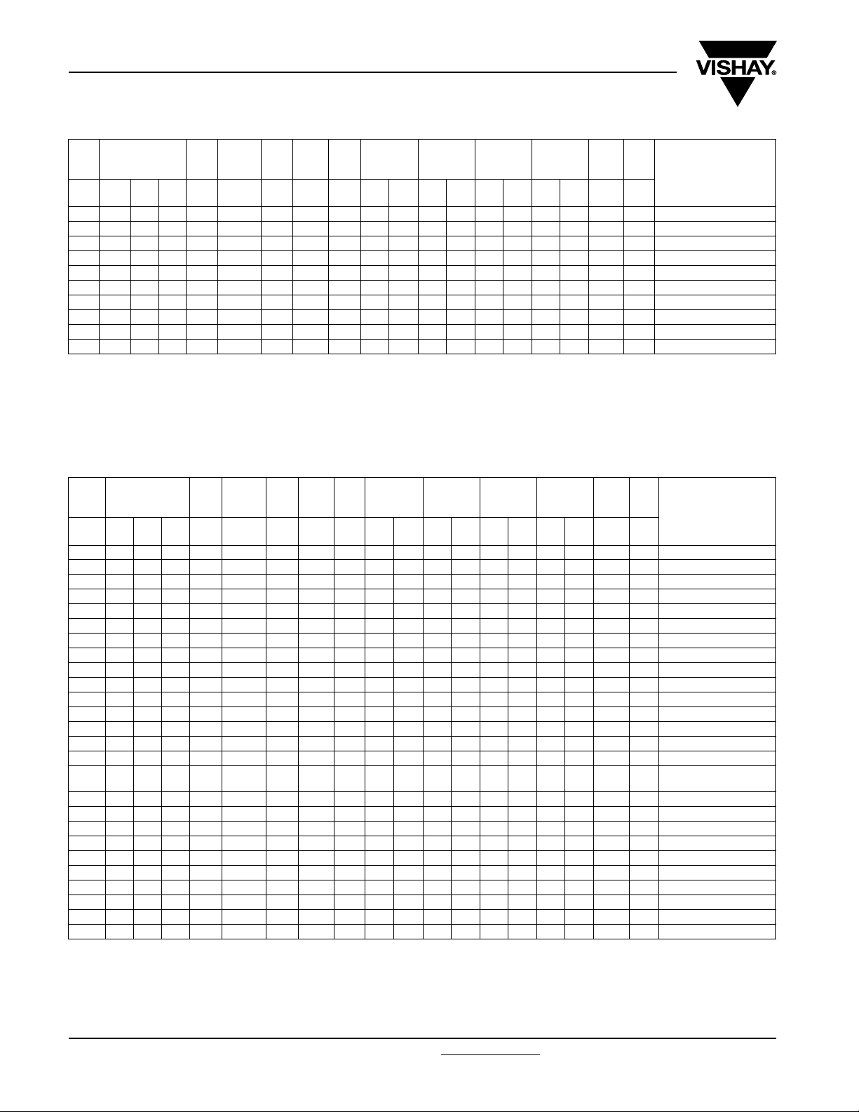
SPECIFIC REFERENCE DATA 900 Vdc
U
= 900 V, U
Ndc
CAP.
DIMENSIONS
(5)
(mm)
(µF) W H L (mm) (mm) (mm) (V/µs) (A)
1.0 9.0 19.0 32.0 27.5 - 0.8 80 80 2.0 - 88.0 - 8.0 - 65 - 5.9 160 MKP1848510094K2
2.0 13.0 23.0 32.0 27.5 - 0.8 80 160 2.5 - 44.0 - 8.0 - 65 - 11.3 115 MKP1848520094K2
3.0 15.0 25.0 32.0 27.5 - 0.8 80 240 3.5 - 29.5 - 8.0 - 65 - 12.1 100 MKP1848530094K2
4.0 18.0 28.0 32.0 27.5 - 0.8 80 320 4.0 - 22.0 - 8.0 - 65 - 16.7 80 MKP1848540094K2
5.0 21.0 31.0 32.0 27.5 - 0.8 80 400 5.0 - 18.0 - 8.0 - 65 - 23.3 65 MKP1848550094K2
6.0 21.0 31.0 32.0 27.5 - 0.8 80 480 5.5 - 15.0 - 8.0 - 65 - 21.4 65 MKP1848560094K2
5.0 18.5 35.5 43.0 37.5 10.2 1.0 40 200 4.0 4.5 36.5 32.0 15.0 13 140 125 37.1 105 MKP1848550094P*
6.0 18.5 35.5 43.0 37.5 10.2 1.0 40 240 4.5 5.0 30.0 27.0 15.0 13 140 125 35.6 105 MKP1848560094P*
7.0 18.5 35.5 43.0 37.5 10.2 1.0 40 280 5.0 5.5 26.0 23.5 15.0 13 140 125 34.1 105 MKP1848570094P*
8.0 18.5 35.5 43.0 37.5 10.2 1.0 40 320 5.0 5.5 22.5 20.5 15.0 13 140 125 32.5 105 MKP1848580094P*
9.0 18.5 35.5 43.0 37.5 10.2 1.0 40 360 5.5 6.0 20.0 18.5 15.0 13 140 125 30.9 105 MKP1848590094P*
10.0 21.5 38.5 43.0 37.5 10.2 1.0 40 400 6.0 6.5 18.5 16.5 15.0 13 140 125 40.7 91 MKP1848610094P*
12.0 21.5 38.5 43.0 37.5 10.2 1.0 40 480 6.5 7.0 15.0 13.5 15.0 13 140 125 37.5 91 MKP1848612094P*
15.0 24.0 44.0 42.0 37.5 10.2 1.0 40 600 8.0 8.5 12.5 11.0 15.0 13 140 125 48.9 77 MKP1848615094P*
16.0 24.0 44.0 42.0 37.5 10.2 1.0 40 640 8.0 8.5 11.5 10.5 15.0 13 140 125 47.2 77 MKP1848616094P*
20.0 30.0 45.0 42.0 37.5
15.0 25.0 45.0 57.5 52.5 20.3 1.2 20 300 6.5 7.5 24.5 22.0 30.0 25 275 250 83 55 MKP1848615094Y*
20.0 25.0 45.0 57.5 52.5 20.3 1.2 20 400 7.0 8.0 18.5 16.5 30.0 25 275 250 75 55 MKP1848620094Y*
22.0 25.0 45.0 57.5 52.5 20.3 1.2 20 440 7.5 8.5 16.5 15.0 30.0 25 275 250 72 55 MKP1848622094Y*
25.0 30.0 45.0 57.5 52.5 20.3 1.2 20 500 8.5 9.5 14.5 13.5 30.0 25 275 250 102 45 MKP1848625094Y*
30.0 30.0 45.0 57.5 52.5 20.3 1.2 20 600 9.5 10.5 12.5 11.0 30.0 25 275 250 92 45 MKP1848630094Y*
35.0 35.0 50.0 57.5 52.5 20.3 1.2 20 700 10.5 11.5 10.5 9.5 30.0 25 275 250 114 40 MKP1848635094Y*
40.0 35.0 50.0 57.5 52.5 20.3 1.2 20 800 12.0 13.0 9.5 8.5 30.0 25 275 250 103 40 MKP1848640094Y*
45.0 45.0 45.0 57.5 52.5 20.3 1.2 20 900 - 14.0 - 7.5 - 25 - 250 192 30 MKP1848645094Y5
50.0 45.0 45.0 57.5 52.5 20.3 1.2 20 1000 - 14.5 - 6.5 - 25 - 250 191 30 MKP1848650094Y5
100.0 70.0 60.0 57.5 52.5 20.3 1.2 20 2000 - 25.0 - 3.5 - 25 - 250 452 20 MKP1848710094Y5
Notes
(1)
Change the * symbol with special code for the terminals
(2)
Maximum rms current at 10 kHz, + 85 °C, Cap. tol. ≤ ± 5 %
(3)
Equivalent series resistance typical values at 10 kHz
(4)
Standard dimension
(5)
Intermediate capacitance values are available on request.
• SPQ = Standard Packing Quantity
www.vishay.com For technical questions, contact: dc-film@vishay.com
284 Revision: 02-Feb-09
Ndc70 °C
(4)
= 1100 V, U
P1 P2
10.2 /
20.3
Ø d
= 650 V
dV/dtI
t
I
PEAK
RMS
(2)
(A)
2
pins4pins2 pins4pins2 pins4pins2 pins4pins
ESR
(mΩ)
tan δ
1 kHz
(3)
< (10
Ndc105 °C
1.0 40 800 9.5 10.0 9.5 8.5 15.0 13 140 125 60 63 MKP1848620094P*
tan δ
10 kHz
-4
)
< (10-4)
MASS SPQ
PART NUMBER
(1)
(g) (pcs)
tan δ
10 kHz
-4
)
< (10-4)
MASS SPQ
PART NUMBER
(1)
(g) (pcs)
Document Number: 28164
MKP 1848 DC-Link
Metallized Polypropylene Film Capacitors
Vishay Roederstein
DC Capacitor MKP Type
SPECIFIC REFERENCE DATA 1100 Vdc
U
= 1100 V, U
Ndc
CAP.
DIMENSIONS
(5)
(mm)
(µF) W H L (mm) (mm) (mm) (V/µs) (A)
1 11.0 21.0 32.0 27.5 - 0.8 95 95 2.5 - 62.0 - 7.0 - 55 - 9.1 130 MKP1848510914K2
2 15.0 25.0 32.0 27.5 - 0.8 95 190 3.5 - 31.0 - 7.0 - 55 - 12.3 100 MKP1848520914K2
3 18.0 28.0 32.0 27.5 - 0.8 95 285 5.0 - 21.0 - 7.0 - 55 - 16.0 80 MKP1848530914K2
4 21.0 31.0 32.0 27.5 - 0.8 95 380 6.5 - 15.5 - 7.0 - 55 - 21.8 65 MKP1848540914K2
5 18.5 35.5 43.0 37.5 10.2 1.0 45 225 5.5 6.0 25.5 23.0 13.0 12.0 115 105 33.7 105 MKP1848550914P*
6 18.5 35.5 43.0 37.5 10.2 1.0 45 270 6.0 6.5 21.5 19.0 13.0 12.0 115 105 31.4 105 MKP1848560914P*
7 21.5 38.5 43.0 37.5 10.2 1.0 45 315 7.0 7.5 18.5 16.5 13.0 12.0 115 105 40.5 91 MKP1848570914P*
8 21.5 38.5 43.0 37.5 10.2 1.0 45 360 4.5 5.0 16.0 14.5 13.0 12.0 115 105 38.2 91 MKP1848580914P*
9 24.0 44.0 42.0 37.5 10.2 1.0 45 405 8.5 9.0 14.0 13.0 13.0 12.0 115 105 52 77 MKP1848590914P*
10 24.0 44.0 42.0 37.5 10.2 1.0 45 450 9.0 9.5 13.0 11.5 13.0 12.0 115 105 49 77 MKP1848610914P*
12 30.0 45.0 42.0 37.5
10 25.0 45.0 57.5 52.5 20.3 1.2 23 230 7.5 8.5 25.5 23.0 25.0 22.0 230 210 84 55 MKP1848610914Y*
12 25.0 45.0 57.5 52.5 20.3 1.2 23 276 8.0 9.0 21.5 19.5 25.0 22.0 230 210 80 55 MKP1848612914Y*
15 25.0 45.0 57.5 52.5 20.3 1.2 23 345 9.0 10.0 17.0 15.5 25.0 22.0 230 210 73 55 MKP1848615914Y*
20 30.0 45.0 57.5 52.5 20.3 1.2 23 460 11.0 12.0 12.5 11.5 25.0 22.0 230 210 94 45 MKP1848620914Y*
22 35.0 50.0 57.5 52.5 20.3 1.2 23 506 12.5 13.5 11.5 10.5 25.0 22.0 230 210 119 40 MKP1848622914Y*
25 35.0 50.0 57.5 52.5 20.3 1.2 23 575 13.5 14.5 10.5 9.0 25.0 22.0 230 210 112 40 MKP1848625914Y*
30 45.0 45.0 57.5 52.5 20.3 1.2 23 720 - 16.5 - 7.5 - 22.0 - 210 192 30 MKP1848630914Y5
60 70.0 60.0 57.5 52.5 20.3 1.2 23 1500 - 30.0 - 3.5 - 22.0 - 210 452 20 MKP1848660914Y5
Notes
(1)
Change the * symbol with special code for the terminals
(2)
Maximum rms current at 10 kHz, + 85 °C, Cap. tol. ≤ ± 5 %
(3)
Equivalent series resistance typical values at 10 kHz
(4)
Standard dimension
(5)
Intermediate capacitance values are available on request.
• SPQ = Standard Packing Quantity
Ndc70 °C
(4)
= 1350 V, U
P1 P2
10.2 /
20.3
Ø d
= 800 V
dV/dtI
t
I
PEAK
RMS
(A)
2
pins4pins2 pins4pins2 pins4pins2 pins4pins
ESR
(2)
(mΩ)
tan δ
1 kHz
(3)
< (10
-4
)
tan δ
10 kHz
< (10-4)
MASS SPQ
PART NUMBER
(g) (pcs)
Ndc105 °C
1.0 45 540 10.5 11.0 10.5 9.5 13.0 12.0 115 105 66 63 MKP1848612914P*
(1)
SPECIFIC REFERENCE DATA 1200 Vdc
U
= 1200 V, U
Ndc
CAP.
DIMENSIONS
(5)
(mm)
(µF) W H L (mm) (mm) (mm) (V/µs) (A)
1 11.0 21.0 32.0 27.5 - 0.8 100 100 2.5 - 60.0 - 6.0 - 54 - 8.8 130 MKP1848510924K2
2 15.0 25.0 32.0 27.5 - 0.8 100 200 4.0 - 30.0 - 6.0 - 54 - 11.7 100 MKP1848520924K2
3 18.0 28.0 32.0 27.5 - 0.8 100 300 5.0 - 20.0 - 6.0 - 54 - 15.2 80 MKP1848530924K2
4 21.0 31.0 32.0 27.5 - 0.8 100 400 6.5 - 15.0 - 6.0 - 54 - 20.6 65 MKP1848540924K2
5 18.5 35.5 43.0 37.5 10.2 1.0 48 240 6.0 6.5 24.5 22.0 12.0 11.0 110 100 32.5 105 MKP1848550924P*
6 18.5 35.5 43.0 37.5 10.2 1.0 48 288 6.5 7.0 20.0 18.5 12.0 11.0 110 100 30.0 105 MKP1848560924P*
7 21.5 38.5 43.0 37.5 10.2 1.0 48 336 7.5 8.0 17.5 15.5 12.0 11.0 110 100 38.9 91 MKP1848570924P*
8 21.5 38.5 43.0 37.5 10.2 1.0 48 384 8.0 8.5 15.5 14.0 12.0 11.0 110 100 36.3 91 MKP1848580924P*
9 24.0 44.0 42.0 37.5 10.2 1.0 48 432 9.0 9.5 13.5 12.5 12.0 11.0 110 100 50 77 MKP1848590924P*
10 24.0 44.0 42.0 37.5 10.2 1.0 48 480 9.5 10.0 12.5 11.0 12.0 11.0 110 100 47 77 MKP1848610924P*
12 30.0 45.0 42.0 37.5
10 25.0 45.0 57.5 52.5 20.3 1.2 24 240 7.5 8.5 24.5 21.5 23.0 21.0 220 200 82 55 MKP1848610924Y*
12 25.0 45.0 57.5 52.5 20.3 1.2 24 288 8.5 9.5 20.5 18.5 23.0 21.0 220 200 77 55 MKP1848612924Y*
Document Number: 28164 For technical questions, contact: dc-film@vishay.com
Revision: 02-Feb-09 285
Ndc70 °C
(4)
= 1500 V, U
P1 P2
10.2 /
20.3
Ø d
= 850 V
dV/dtI
t
I
PEAK
RMS
(A)
2
pins4pins2 pins4pins2 pins4pins2 pins4pins
ESR
(2)
(mΩ)
tan δ
1 kHz
(3)
< (10
-4
)
tan δ
10 kHz
< (10-4)
MASS SPQ
PART NUMBER
(g) (pcs)
Ndc105 °C
1.0 48 576 11.0 11.5 10.0 9.0 12.0 11.0 110 100 63 63 MKP1848612924P*
www.vishay.com
(1)

MKP 1848 DC-Link
Vishay Roederstein
Metallized Polypropylene Film Capacitors
DC Capacitor MKP Type
DIMENSIONS
CAP.
(5)
(mm)
(µF) W H L (mm) (mm) (mm) (V/µs) (A)
15 25.0 45.0 57.5 52.5 20.3 1.2 24 360 9.5 10.5 16.5 14.5 23.0 21.0 220 200 69 55 MKP1848615924Y*
20 35.0 50.0 57.5 52.5 20.3 1.2 24 480 12.5 13.5 12.5 11.0 23.0 21.0 220 200 119 40 MKP1848620924Y*
22 35.0 50.0 57.5 52.5 20.3 1.2 24 528 13.0 14.0 11.0 10.0 23.0 21.0 220 200 114 40 MKP1848622924Y*
25 35.0 50.0 57.5 52.5 20.3 1.2 24 600 14.0 15.0 10.0 9.0 23.0 21.0 220 200 104 40 MKP1848625924Y*
30 45.0 45.0 57.5 52.5 20.3 1.2 24 750 - 17.0 - 7.0 - 21.0 - 200 191 30 MKP1848630924Y5
60 70.0 60.0 57.5 52.5 20.3 1.2 24 1560 - 28.5 - 3.5 - 21.0 - 200 450 15 MKP1848660924Y5
Notes
(1)
Change the * symbol with special code for the terminals
(2)
Maximum rms current at 10 kHz, + 85 °C, Cap. tol. ≤ ± 5 %
(3)
Equivalent series resistance typical values at 10 kHz
(4)
Standard dimension
(5)
Intermediate capacitance values are available on request.
• SPQ = Standard Packing Quantity
P1 P2
(4)
Ø d
dV/dtI
t
PEAKIRMS
(A)
2
pins4pins2 pins4pins2 pins4pins2 pins4pins
ESR
(mΩ)
tan δ
1 kHz
(3)
< (10
CONSTRUCTION
Description
Low inductive wound cell elements of metallised polypropylene film, potted with resin in a flame retardant case.
tan δ
10 kHz
-4
)
< (10-4)
MASS SPQ
PART NUMBER
(g) (pcs)
(1)
MOUNTING
The capacitors unit is designed for mounting on PCB. The capacitors shall be mechanically fixed by the leads and body must be
clamped to withstand vibration and shock.
Space Requirements on Printed-Circuit Board
The maximum length and width of film capacitors is shown in the figure:
• Eccentricity as in figure. The maximum eccentricity is smaller than or equal to the lead diameter of the product concerned
• Product height with seating plane as given by “IEC 60717” as reference: h
Eccentricity
= I + 0.5 mm
I
max.
Storage temperature
• Storage temperature: T
= - 25 °C to + 40 °C with RH maximum 80 % without condensation
stg
Ratings and Characteristics Reference Conditions
Unless otherwise specified, all electrical values apply to an ambient free temperature of 23 °C ± 1 °C, an atmospheric pressure
of 86 kPa to 106 kPa and a relative humidity of 50 % ± 2 %.
For reference testing, a conditioning period shall be applied over 96 h ± 4 h by heating the products in a circulating air oven at
the rated temperature and a relative humidity not exceeding 20 %.
≤ h + 0.5 mm
max.
b
= b + 0.5 mm
max.
www.vishay.com For technical questions, contact: dc-film@vishay.com
286 Revision: 02-Feb-09
Document Number: 28164

MKP 1848 DC-Link
CHARACTERISTICS
Capacitance (typical curve) Insulation resistance (typical curve)
4
C/C
(%)
2
0
- 2
- 4
- 6
- 60
1.5
1.4
1.3
1.2
1.1
Hot spot
Ndc
temperature
/U
1.0
opdc
U
0.9
0.8
0.7
0.6
0.5
2
10
103 104 105 10
-20 20 60 100T
Lifetime expectancy (typical curve) Impedance vs. frequency (typical curve)
Impedance vs. frequency (typical curve) Impedance vs. frequency (typical curve)
105 °C
Metallized Polypropylene Film Capacitors
DC Capacitor MKP Type
5
10
RC (s)
4
10
3
amb
85 °C
70 °C
Lifetime expectancy (h)
(°C)
10
0
10.0
1.0
Z (Ω)
0.1
0.01
6
4
10
20 40 60
2.0
4.0
µF
8.0 µF
5
10
Vishay Roederstein
80
T
amb
Pitch 27.5 mm
µF
6
10
(°C)
f (Hz)
100
7
10
10.0
Z (Ω)
1.0
0.1
0.01
0.0
Pitch 37.5 mm
15.0 µF
25.0 µF
40.0 µF
4
10
10
5
10
6
f (Hz)
10
10.0
Pitch 52.5 mm
Z (Ω)
1.0
0.1
45.0 µF
60.0 µF
80.0 µF
0.01
0.0
7
4
10
10
5
10
6
f (Hz)
10
7
Document Number: 28164 For technical questions, contact: dc-film@vishay.com
www.vishay.com
Revision: 02-Feb-09 287
MKP 1848 DC-Link
Vishay Roederstein
Metallized Polypropylene Film Capacitors
DC Capacitor MKP Type
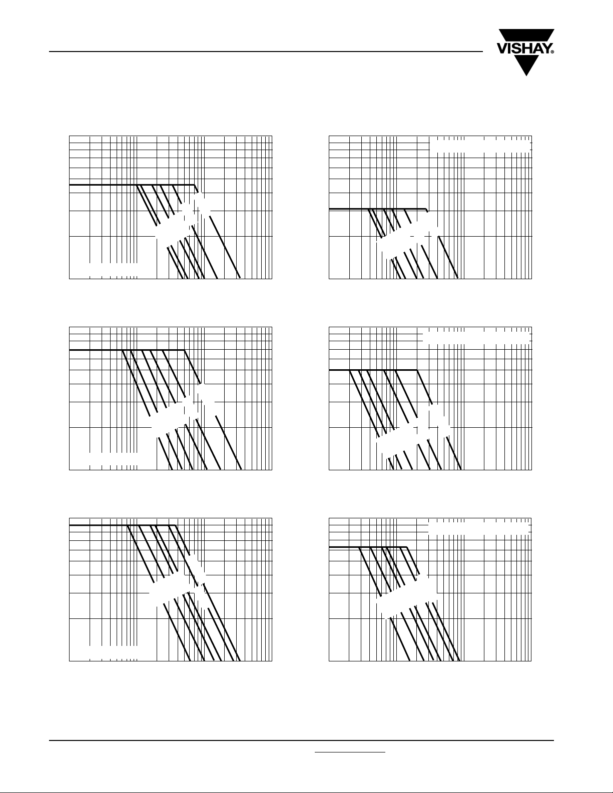
MAXIMUM PEAK TO PEAK RIPPLE VOLTAGE AS A FUNCTION OF FREQUENCY
100
(1)
80 µF
Peak to peak ripple voltage (Upp)
T
≤ 85 °C, 450 Vdc
amb
10
2
10
(1)
Limited by maximum ripple voltage 0.1 x U
10
3
100
(1)
45 µF
35 µF
15 µF
8.0 µF
2.0 µF
10
4
f (Hz)
Ndc
10
5
100
(1)
8.0 µF
15 µF
35 µF
45 µF
80 µF
Peak to peak ripple voltage (Upp)
10
2
10
(1)
Limited by maximum ripple voltage 0.1 x U
10
3
100
(1)
85 °C < T
2.0 µF
85 °C < T
≤ 105 °C, 450 Vdc
amb
4
10
amb
f (Hz)
Ndc
≤ 105 °C, 700 Vdc
10
5
80 µF
Peak to peak ripple voltage (Upp)
T
≤ 85 °C, 700 Vdc
amb
10
2
10
(1)
Limited by maximum ripple voltage 0.1 x U
10
3
100
(1)
50 µF
Peak to peak ripple voltage (Upp)
T
≤ 85 °C, 900 Vdc
amb
10
2
10
(1)
Limited by maximum ripple voltage 0.1 x U
10
3
55 µF
30 µF
20 µF
12 µF
15 µF
8.0 µF
8.0 µF
10
2.0 µF
5.0 µF
10
2.0 µF
2.0 µF
8.0 µF
12 µF
30 µF
55 µF
80 µF
Peak to peak ripple voltage (Upp)
10
4
f (Hz)
Ndc
10
5
2
10
(1)
Limited by maximum ripple voltage 0.1 x U
10
3
10
4
f (Hz)
Ndc
10
5
100
85 °C < T
(1)
2.0 µF
5.0 µF
8.0 µF
15 µF
20 µF
50 µF
≤ 105 °C, 900 Vdc
amb
Peak to peak ripple voltage (Upp)
4
f (Hz)
Ndc
10
5
10
2
10
(1)
Limited by maximum ripple voltage 0.1 x U
10
3
10
4
f (Hz)
Ndc
10
5
www.vishay.com For technical questions, contact: dc-film@vishay.com
Document Number: 28164
288 Revision: 02-Feb-09

MKP 1848 DC-Link
Metallized Polypropylene Film Capacitors
DC Capacitor MKP Type
MAXIMUM PEAK TO PEAK RIPPLE VOLTAGE AS A FUNCTION OF FREQUENCY
1000
(1)
100
Peak to peak ripple voltage (Upp)
T
≤ 85 °C, 1100 Vdc
amb
10
2
10
(1)
Limited by maximum ripple voltage 0.1 x U
10
3
1000
(1)
30 µF
10 µF
12 µF
5.0 µF
2.0 µF
10
4
f (Hz)
10
Ndc
1000
(1)
100
2.0 µF
5.0 µF
10 µF
12 µF
30 µF
Peak to peak ripple voltage (Upp)
5
10
2
10
(1)
Limited by maximum ripple voltage 0.1 x U
10
3
1000
(1)
Vishay Roederstein
85 °C < T
85 °C < T
≤ 105 °C, 1100 Vdc
amb
4
10
amb
f (Hz)
Ndc
≤ 105 °C, 1200 Vdc
10
5
100
Peak to peak ripple voltage (Upp)
T
≤ 85 °C, 1200 Vdc
amb
10
2
10
(1)
Limited by maximum ripple voltage 0.1 x U
10
3
30 µF
12 µF
10 µF
5.0 µF
10
2.0 µF
4
Ndc
f (Hz)
10
100
2.0 µF
5.0 µF
10 µF
12 µF
30 µF
Peak to peak ripple voltage (Upp)
10
5
2
10
(1)
Limited by maximum ripple voltage 0.1 x U
10
3
10
4
Ndc
f (Hz)
10
5
Document Number: 28164 For technical questions, contact: dc-film@vishay.com
www.vishay.com
Revision: 02-Feb-09 289

MKP 1848 DC-Link
Vishay Roederstein
Metallized Polypropylene Film Capacitors
DC Capacitor MKP Type
HEAT CONDUCTIVITY AND HOT SPOT TEMPERATURE
W
max.
(mm)
9.0 31 - -
11.0 37 - -
13.0 42 - -
15.0 48 - -
18.0 58 - -
18.5 - 89 -
21.0 68 - -
21.5 - 102 -
24.0 - 116 -
25.0 - - 152
30.0 - 134 181
35.0 - - 197
45.0 - - 213
87.0 - - 341
PITCH 27.5 mm PITCH 37.5 mm PITCH 52.5 mm
HEAT CONDUCTIVITY (mW/°C)
POWER DISSIPATION AND MAXIMUM COMPONENT TEMPERATURE RISE
The power dissipation must be limited in order not to exceed the maximum allowed component temperature rise as a function of
the free air ambient temperature.
The component temperature rise (ΔT) can be measured or calculated by ΔT = P/G:
• ΔT = Component temperature rise (°C)
• P = Power dissipation of the component (mW)
• G = Heat conductivity of the component (mW/°C)
MEASURING THE COMPONENT TEMPERATURE
Thermocouple
The temperature is measured in unloaded (T
The temperature rise is given by ΔT = Tc - T
To avoid thermal radiation or convection, the capacitor must be tested in a closed area from air circulation.
) and maximum loaded condition (TC).
amb
.
amb
www.vishay.com For technical questions, contact: dc-film@vishay.com
290 Revision: 02-Feb-09
Document Number: 28164

MKP 1848 DC-Link
Metallized Polypropylene Film Capacitors
Vishay Roederstein
DC Capacitor MKP Type
APPLICATION NOTE AND LIMITING CONDITIONS
These capacitors are not suitable for mains applications as across-the-line capacitors without additional protection. These mains
applications are strictly regulated in safety standards and therefore electromagnetic interference suppression capacitors
conforming the standards must be used.
To select the capacitor for a certain application, the following conditions must be checked:
1. The peak voltage (U
2. The peak-to-peak ripple voltage (U
) shall not be greater than the rated DC voltage (U
P+
) shall not be greater than 0.1 x (U
P-P
Non reversing recurrent waveform
Up+ U
Ndc
U
Voltage (V)
t
p-
3. The voltage peak slope (dU/dt) shall not exceed the pulse slope at the DC voltage rating.
If the pulse voltage is lower than the rated DC voltage, the rated voltage pulse slope may be multiplied by U
by the applied voltage.
For all other pulses following equation must be fulfilled:
Ndc
Ndc
)
)
and divided
Ndc
T
2
dU
⎛⎞
--------
∫
⎝⎠
dt
0
2
dt U
Ndc
dU
⎛⎞
--------
×<××
⎝⎠
dt
rated
T is the pulse duration
4. The maximum component surface temperature rise must be lower than 15 °C.
MAXIMUM REPETITIVE PEAK VOLTAGES
The capacitor unit may be subjected to the following surge without any significant reduction of lifetime expectancy
REPETITIVE SURGE VOLTAGE MAXIMUM DURATION PER DAY
1.1 x U
1.15 x U
1.2 x U
1.3 x U
1.5 x U
Ndc
Ndc
Ndc
Ndc
Ndc
30 % on load duration
30 min
5 min
1 min
110 ms
Document Number: 28164 For technical questions, contact: dc-film@vishay.com
Revision: 02-Feb-09 291
www.vishay.com

MKP 1848 DC-Link
Vishay Roederstein
Metallized Polypropylene Film Capacitors
DC Capacitor MKP Type
INSPECTION REQUIREMENTS
General Notes:
Sub-clause numbers of tests and performance requirements refer to the “Sectional Specification, Publication IEC 61071.
SUB-CLAUSE NUMBER AND TEST CONDITIONS PERFORMANCE REQUIREMENTS
ROUTINE TEST-FINAL INSPECTION
5.14.2.1 External inspection,
5.14.2.2 Dimensions See specification drawing
5.3.1 Capacitance 1 kHz at room temperature See specific reference data
5.3.2 tan δ 1 kHz at room temperature See specific reference data
5.5.1.2 Voltage test between terminal
5.7 Insulation resistance U
TYPE TESTS
5.14.2 External inspection Check for finish, marking and overall
5.14.0 Initial measurements Capacitance at 1 kHz
5.14.1.1.4 Robustness of terminations
visual examination
IEC 60068-2-21
10 kHz at room temperature
1.5 x U
Duration 10 s
Ndc
at room temperature
U
Ndc
at room temperature
Duration 1 min
dimensions
tan δ at 10 kHz
Tensile Ua1
Wire diameter section load
≤ 0.8 mm ≤ 0.5 mm
≤ 1.25 mm ≤ 1.2 mm
Duration 10 s ± 1 s
at T
amb
.
2
10 N
2
20 N
Ndc
≤ 500 V measuring voltage 100 V
> 500 V m,easuring voltage 500 V
Legible marking as specified
No visible damage or puncture
No flashover
See specific reference data
Legible marking and finish as specified
Dimensions: see specific drawing
Bending Ub method 1
Wire diameter section load
≤ 0.8 mm ≤ 0.05 mm
≤ 1.25 mm ≤ 0.019 mm
4 x 90 °,
Duration 2 s to 3 s/bend
5.14.1.6 Resistance to soldering heat
5.14.4 Final measurements Capacitance
5.14.0 Initial measurements Capacitance at 1 kHz
5.14.3.1 Vibration
5.14.3.2 Shock or impact
5.14.4 Final measurements Capacitance
www.vishay.com For technical questions, contact: dc-film@vishay.com
292 Revision: 02-Feb-09
IEC 60068-2-20
IEC 60068-2-6
IEC 60068-2-6
No predrying, Method 1A
Solder bath: 260 °C ± 5 °C
tan δ
tan δ at 10 kHz
10 Hz to 55 Hz: amplitude ± 0.35 mm or
acceleration 98 m/s
Test duration: 10 frequency cycles, 3 axes
offset from each other by 90°
1 octave/min
Pulse shape: half sine
Acceleration: 490 m/s
Duration t of pulse: 11 ms
Visual examination
tan δ
2
3
10 N
3
20 N
|ΔC/C| ≤ 0.5 %
Increase of tan δ ≤ 0.0050
Compared to values measured in 5.14.0
No visible damage
2
No visible damage
|ΔC/C| ≤ 0.5 %
Increase of tan δ ≤ 0.0050
Compared to values measured in 5.14.0
Document Number: 28164

MKP 1848 DC-Link
Metallized Polypropylene Film Capacitors
Vishay Roederstein
DC Capacitor MKP Type
SUB-CLAUSE NUMBER AND TEST CONDITIONS PERFORMANCE REQUIREMENTS
5.5.3.1 Initial measurements Capacitance at 1 kHz
5.5.3.2 Voltage test between terminal 1.5 x U
5.5.3.3 Final measurements Capacitance
5.9.1 Initial measurements Capacitance at 1 kHz
5.9.2 Surge discharge test 1.1 x U
5.9.3 Voltage test between terminal Within 5 min after the surge discharge test
5.9.3 Final measurements Capacitance
5.11.1 Initial measurements Capacitance at 1 kHz
5.11.2 Self healing test 1.5 x U
5.11.3 Final measurements Capacitance
5.13.0 Initial measurements Capacitance at 1 kHz
5.13.1 Change of temperature acc to
IEC 60068-2-14
5.13.2 Damp heat steady state
Acc. to IEC 60068-2-78
5.5.3.2 Voltage test between terminal 1.5 x U
5.13.3 Final measurements
5.10.0 Initial measurements Capacitance at 1 kHz
5.10.1 Thermal stability test under
overload conditions
5.10.2 Final measurements Measure the temperature every 1.5 h during
Document Number: 28164 For technical questions, contact: dc-film@vishay.com
Revision: 02-Feb-09 293
tan δ at 10 kHz
R insulation
at T
amb
.
Ndc
Duration 60 s
|ΔC/C| ≤ 0.5 %
tan δ
R insulation
Increase of tan δ ≤ 1.2 initial tan δ + 0.0001
R insulation ≥ 50 % of specified values
tan δ at 10 kHz
Ndc
Number of discharges: 5
Time lapse: every 2 min (10 min total)
Duration 60 s
1.5 x U
Ndc
at T
amb
.
|ΔC/C| ≤ 1.0 %
tan δ at 10 kHz
tan δ ≤ 1.2 initial tan δ + 0.0001
Compared to values measured in 5.9.1
tan δ at 10 kHz
Ndc
Duration 10 s
Number of clearings ≤ 5
Clearing = voltage drop of 5 %
increase the voltage at 100 V/s till 5
clearings occur
with a max. of 2.5 x U
Ndc
for a duration of 10 s
|ΔC/C| ≤ 0.5 %
tan δ
tan δ ≤ 1.2 x initial tan δ + 0.0001
Compared to values measured in 5.11.1
tan δ at 10 kHz
Tes t Nb
T
= 85 °C
max.
T
= - 40 °C
min.
Transition time: 1 h, equivalent to 1 °C/min
5 cycles
Tes t Ca
T
= 40 ± 2 °C
max.
RH = 93 ± 3 %
Duration 56 days
at ambient temperature
Ndc
Duration 60 s
Visual examination No puncturing or flashover
Self healing punctures are permitted
Capacitance
tan δ at 1 U
rms
10 kHz
|ΔC/C| ≤ 2.0 %
Increase of tan δ ≤ 0.0150
Compared to values measured in 5.13.0
tan δ at 10 kHz
Natural cooling T
1.21 x P
121 x (I
x f
for I
2
= 10 kHz
f
2
= (U2/2) x W2 x C x tan δ =
max.
2
max./W2
(see specific reference data)
max.
± 5 °C
amb
x c) x tan δ2 with W2 = 2 x p
Duration 48 h
temperature rise < 1 °C
the last 6 h
Capacitance
|ΔC/C| ≤ 2 %
Increase of tan δ ≤ 1.2 x initial δ + 0.0150
tan δ at 10 kHz
www.vishay.com

MKP 1848 DC-Link
Vishay Roederstein
Metallized Polypropylene Film Capacitors
DC Capacitor MKP Type
SUB-CLAUSE NUMBER AND TEST CONDITIONS PERFORMANCE REQUIREMENTS
5.12 Resonance frequency
measurement
5.10.0 Initial measurements Capacitance at 1 kHz
5.15.1 Endurance test between terminals Sequence
5.15.2 Final measurements Capacitance
5.16.3.0 Initial measurements Capacitance at 1 kHz
5.16.3.1 Destruction test sequence
DC voltage with superimposed
AC voltage switched to high
DC voltage
5.5.3 Voltage test between terminal 1.5 x U
5.16.3.2 Final measurements
Impedance analyser at T
tan δ at 10 kHz
1.4 x U
Duration 250 h
1000 x discharge at 1.4 x I (maximum
repetitive peak current in continuous
operation)
1.4 x U
Duration 250 h
tan δ
at T
1.3 x U
1.1 x in (I
Duration = 5 min
Switch to high DC voltage = 2 x U
Duration 10 s
Apply number of cycles till capacitance drop
(open circuit) occur.
Duration 60 s
Visual examination No puncturing or flashover
at T
Ndc
max.
at T
Ndc
max.
= 85 °C
max.
with superimposed AC voltage at
Ndc
)
rms
at T
Ndc
amb
amb
= 85 °C
= 85 °C
Ndc
< 0.9 times the value as specified in typical
curve “Resonant frequency” of this
specification
|ΔC/C| ≤ 3 %
Increase of tan δ ≤ 0.0150
Compared to values measured in 5.15.0
Capacitance value < 10 % of measured in
5.16.3.0
Self healing punctures are permitted
www.vishay.com For technical questions, contact: dc-film@vishay.com
294 Revision: 02-Feb-09
Document Number: 28164

Legal Disclaimer Notice
Vishay
Disclaimer
All product specifications and data are subject to change without notice.
Vishay Intertechnology, Inc., its affiliates, agents, and employees, and all persons acting on its or their behalf
(collectively, “Vishay”), disclaim any and all liability for any errors, inaccuracies or incompleteness contained herein
or in any other disclosure relating to any product.
Vishay disclaims any and all liability arising out of the use or application of any product described herein or of any
information provided herein to the maximum extent permitted by law. The product specifications do not expand or
otherwise modify Vishay’s terms and conditions of purchase, including but not limited to the warranty expressed
therein, which apply to these products.
No license, express or implied, by estoppel or otherwise, to any intellectual property rights is granted by this
document or by any conduct of Vishay.
The products shown herein are not designed for use in medical, life-saving, or life-sustaining applications unless
otherwise expressly indicated. Customers using or selling Vishay products not expressly indicated for use in such
applications do so entirely at their own risk and agree to fully indemnify Vishay for any damages arising or resulting
from such use or sale. Please contact authorized Vishay personnel to obtain written terms and conditions regarding
products designed for such applications.
Product names and markings noted herein may be trademarks of their respective owners.
Document Number: 91000 www.vishay.com
Revision: 18-Jul-08 1
 Loading...