

Page 1
MKP 1840-M
Vishay Film Capacitors
p 1of 13
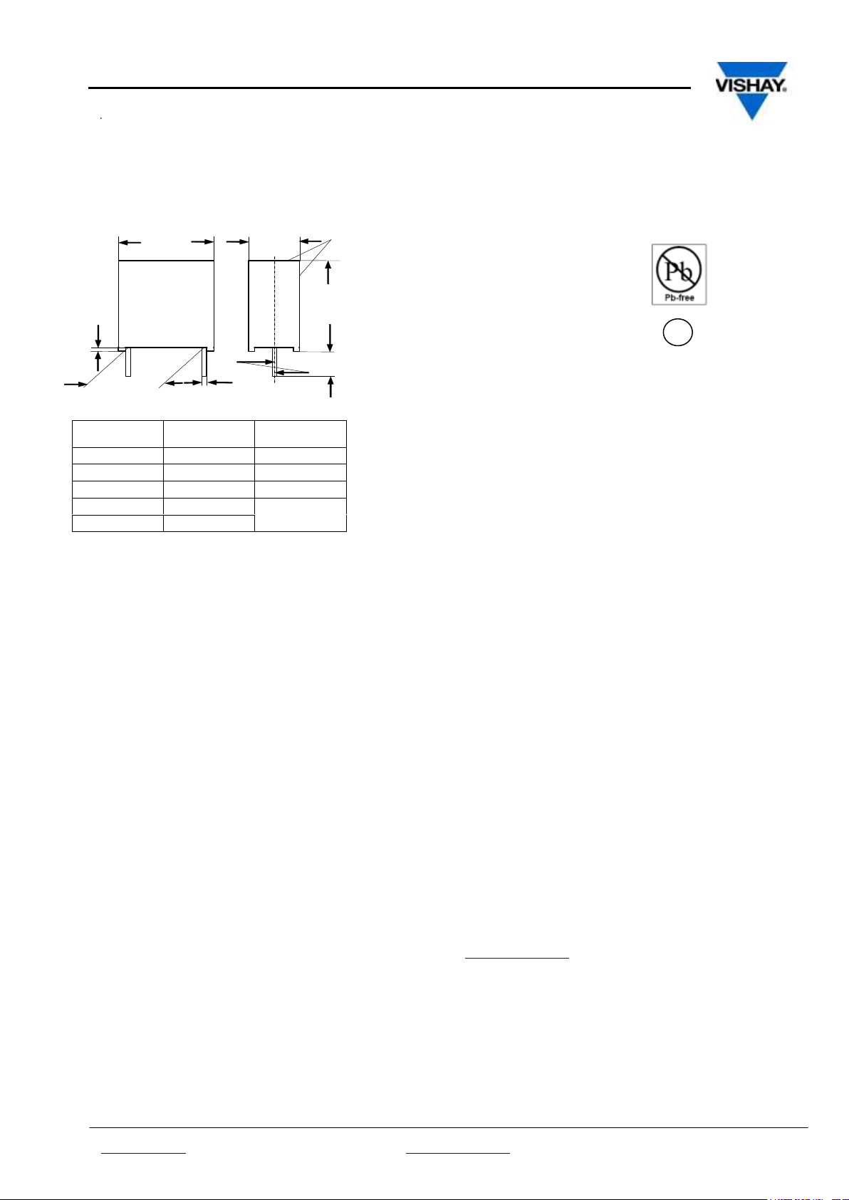
Lead diameter
dt (mm)
w
(mm)
Pitch
(mm)
0.5 ± 0.05
-
5
0.6 ± 0.06
-
7.5 - 10
0.8 ± 0.08
-
15 - 27.5
0.8 ± 0.08
< 16
37.5
1.0 ± 0.1
≥ 16
RoHS
Compliant
e3
Dimensions in millimeters
Marking
0.6
6 -1
± 0.4
Ø 0.8
Pitch
± 0.4
w
max.
l
max.
h
max.
Metallized Polypropylene Capacitor-Mini Version (M)
APPLICATIONS
High frequency and pulse operations. Deflection circuits in TVsets (S-correction). SMPS, loudspeaker crossover networks,
electronic ballast, storage, filter, timing and sample and hold
circuits
REFERENCE STANDARDS
IEC 60384-16
MARKING
C-value; tolerance; rated voltage; manufacturer’s type ; code for
dielectric material; manufacturer location; manufacturer’s logo;
year and week;
DIELECTRIC
Polypropylene film
ELECTRODES
Metallized
CONSTRUCTION
Mono and internal series contruction
RATED DC VOLTAGES :
250 V, 400 V, 630 V, 1000 V,
RATED AC VOLTAGES :
160 V, 220 V, 250 V/ 400 V,
500 V,
www.vishay.com for technical questions contact: dc-film@Vishay.com Document Number: 26018
Revision: 04 March 10
MKP Radial Potted Type
FEATURES
5 to 37.5 mm lead pitch.Supplied loose in box, taped on reel
and Ammopack
RoHS compliant
ENCAPSULATION
Plastic case, epoxy resin sealed, flame retardant
UL-class 94 V-0
CLIMATIC TESTING CLASS ACC.TO EN 60068-1
55/100/56
CAPACITANCE RANGE
1000 pF to 6.8 µF
CAPACITANCE TOLERANCE
±5%, ±2.5%, ± 2%
LEADS
Tinned wire
MAXIMUM APPLICATION TEMPERATURE
100°C
DETAIL SPECIFICATION
For more detailed data and test requirements contact:
dc-film@Vishay.com
Page 2
MKP 1840-M
Vishay Film Capacitors
p2 of 13
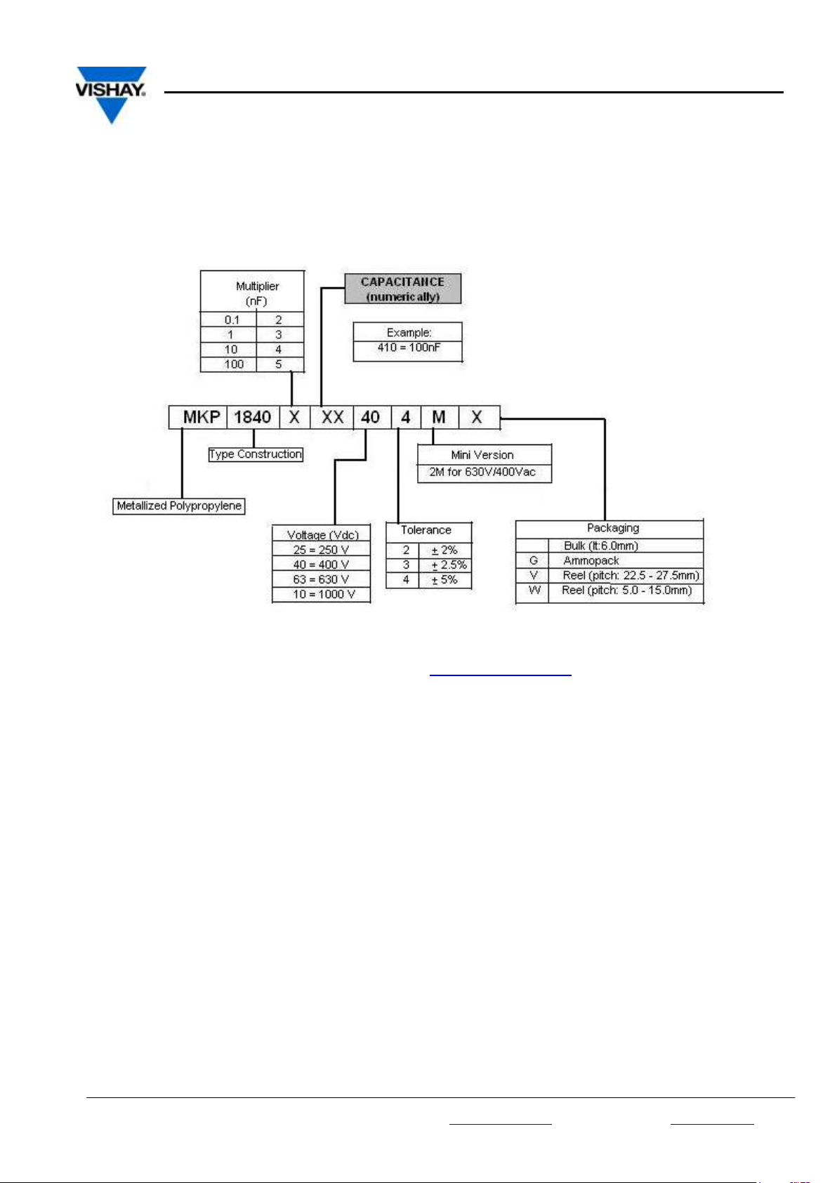
COMPOSITION OF CATALOGUE NUMBER
Notes
1. For detailed tape specifications refer to Packaging information” www.vishay.com/doc?28139
Document Number: 26018 for technical questions contact: dc-film@Vishay.com www.vishay.com
Revision: 04 March 10
Page 3
MKP 1840-M
Vishay Film Capacitors
p 3of 13
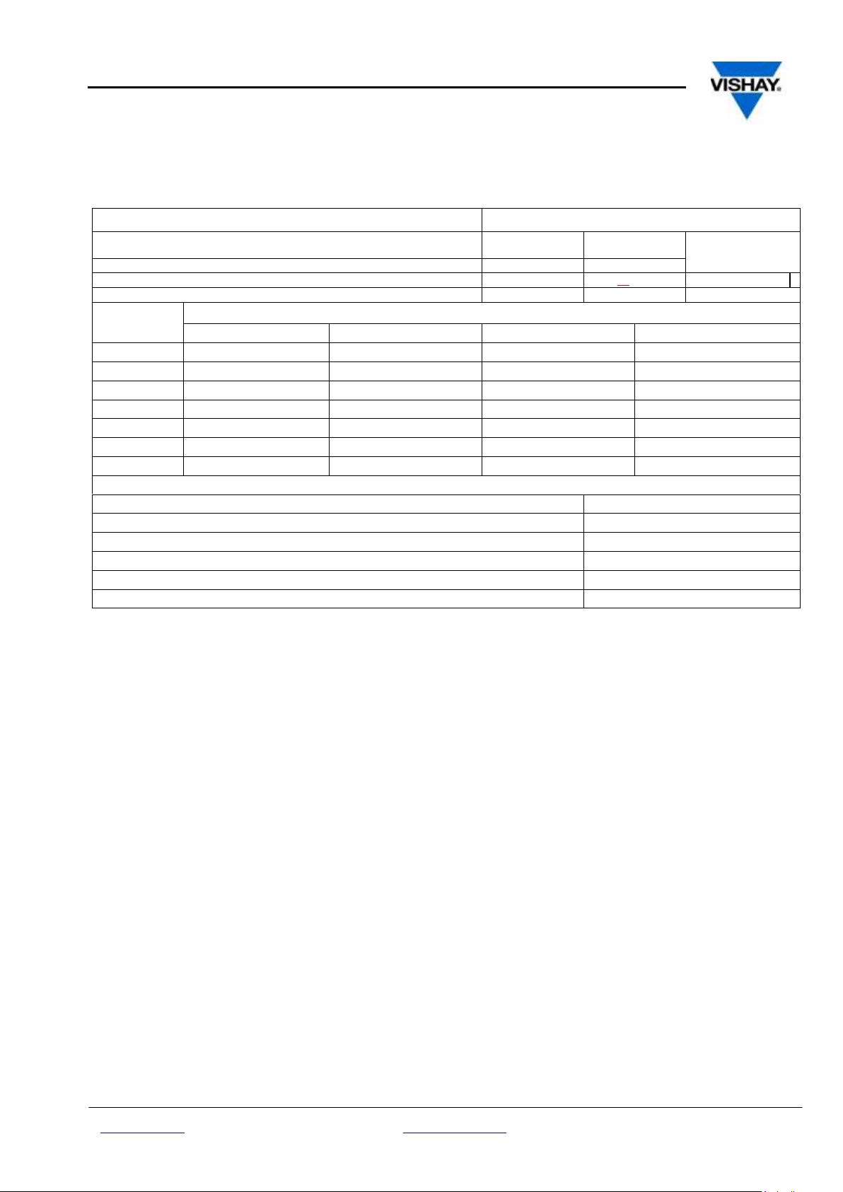
DESCRIPTION
VALUE
Tangent of loss angle:
at 1KHz
at 10KHz
at 100KHz
C ≤ 0.1 μF
≤ 4 X 10
-4
≤ 6 X 10
-4
≤ 40 X 10
-4
0.1 μF < C ≤ 1.0 μF
≤ 4 X 10
-4
≤ 10 X 10
-4
-
C > 1.0 μF
≤ 10 X 10
-4
-
-
Pitch ( mm)
Maximum pulse rise time (dU/dt)R [ V /µs]
250 V dc
400 V dc
630 V dc
1000 V dc
5
360
540
1080
-
7.5
215
325
510
-
10
150
240
340
1365
15
90
135
185
680
22.5
55
80
110
370
27.5
40
65
85
285
37.5
30
45
60
195
If the max. pulse voltage is less than the rated voltage higher dU/dt values can be permitted.
R between leads, for C ≤ 1.0 µF at 100 V; 1 minute
> 100000 MΩ
RC between leads, for C 1.0 µF at 100 V; 1 minute
> 100000 s
R between leads and case; 100 V; 1 minute
> 30000 MΩ
Withstanding (DC) voltage (Cut off current 10mA) rise time 100 V/S
1.6 X U
Rdc
, 1 Minute
Withstanding (DC) voltage between leads and case
500 V; 1 Minute
Maximum application temperature
100°C
SPECIFIC REFERENCE DATA
www.vishay.com for technical questions contact: dc-film@Vishay.com Document Number: 26018
Revision: 04 March 10
Page 4
MKP 1840-M
Vishay Film Capacitors
p4 of 13
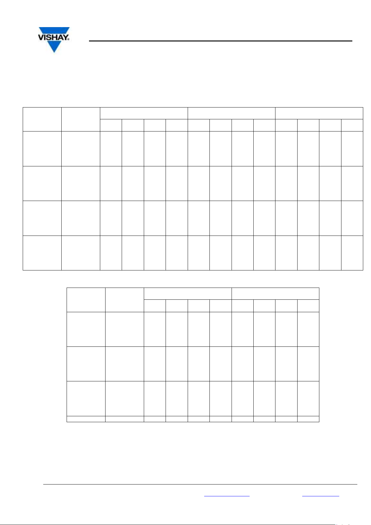
Capacitance
Capacitance
Code
VOLTAGE CODE 25
250 V dc/160 V ac
VOLTAGE CODE 40
400 Vdc /220 Vac **
VOLTAGE CODE 63
630 Vdc /250 Vac**
w
(mm)
h
(mm)
l
(mm)
Pitch
(mm)
w
(mm)
h
(mm)
l
(mm)
Pitch
(mm)
W
(mm)
h
(mm)
l
(mm)
Pitch
(mm)
1000 pF
-210
- - - - - - -
-
3.0
6.5
7.5
5.0
1500 pF
-215
- - - - - - -
-
3.0
6.5
7.5
5.0
2200 pF
-222
- - - - - - -
-
3.5
8.5
7.5
5.0
3300 pF
-233
- - - - - - -
-
3.0
8.5
10.0
7.5
4700 pF
-247
- - - - - - -
-
3.0
8.5
10.0
7.5
6800 pF
-268
- - -
-
3.0
6.5
7.5
5.0
3.0
8.5
10.0
7.5
0.01 µF
-310
3.0
6.5
7.5
5.0
3.5
8.5
7.5
5.0
4.0
9.0
10.0
7.5
0.015 µF
-315
3.0
6.5
7.5
5.0
3.0
8.5
10.0
7.5
4.5
9.5
10.3
7.5
0.022 µF
-322
3.5
8.5
7.5
5.0
4.0
9.0
10.0
7.5
4.5
9.5
13.0
10.0
0.033 µF
-333
3.5
8.5
7.5
5.0
4.5
9.5
10.3
7.5
5.5
10.5
13.0
10.0
0.047 µF
-347
4.0
9.0
10.0
7.5
5.0
10.5
10.3
7.5
6.5
11.5
13.0
10.0
0.068 µF
-368
4.0
9.0
10.0
7.5
5.7
11.5
10.3
7.5
6.0
12.0
18.0
15.0
0.10 µF
-410
5.0
10.5
10.3
7.5
5.5
10.5
18.0
15.0
6.0
12.0
18.0
15.0
0.15 µF
-415
5.5
10.5
13.0
10.0
6.0
12.0
18.0
15.0
8.5
14.5
18.0
15.0
0.22 µF
-422
6.5
11.5
13.0
10.0
7.5
13.5
18.0
15.0
8.5
17.5
18.0
15.0
0.33 µF
-433
6.5
12.5
18.0
15.0
8.5
17.5
18.0
15.0
9.0
17.0
26.5
22.5
0.47 µF
-447
7.5
13.5
18.0
15.0
7.5
15.5
26.5
22.5
10.5
18.5
26.5
22.5
0.68 µF
-468
8.5
14.5
18.0
15.0
10.5
18.5
26.5
22.5
11.5
20.5
31.5
27.5
1.0 µF
-510
8.5
16.5
16.5
22.5
11.0
21.0
26.5
22.5
13.5
23.5
31.5
27.5
1.5 µF
-515
10.5
18.5
26.5
22.5
13.5
23.5
31.5
27.5
16.5
29.5
31.5
27.5
2.2 µF
-522
11.0
21.0
26.5
22.5
15.0
24.5
31.5
27.5
18.0
33.0
31.5
27.5
3.3 µF
-533
13.5
23.5
31.5
27.5
18.0
28.0
31.5
27.5
20.0
40.0
42.5
37.5
4.7 µF
-547
15.0
24.5
31.5
27.5
18.0
32.5
41.5
37.5
20.0
40.0
42.5
37.5
6.8 µF
-568
14.5
24.5
41.5
37.5
20.0
40.0
42.5
37.5
- - -
-
Capacitance
Capacitance
Code
VOLTAGE CODE 63
630 Vdc /400 Vac**
VOLTAGE CODE 10
1000 Vdc /500 Vac **
w
(mm)
h
(mm)
l
(mm)
Pitch
(mm)
w
(mm)
h
(mm)
l
(mm)
Pitch
(mm)
1000 pF
-210
- - - - - - -
-
1500 pF
-215
- - - - - - - - 2200 pF
-222
- - - - - - -
-
3300 pF
-233
- - - - - - -
-
4700 pF
-247
- - -
-
4.0
9.0
13.0
10
6800 pF
-268
- - -
-
4.0
9.0
13.0
10
0.01 µF
-310
4.5
9.5
13.0
10*
5.5
10.5
13.0
10
0.015 µF
-315
5.5
10.5
13.0
10*
6.5
11.5
13.0
10
0.022 µF
-322
6.5
11.5
13.0
10*
5.5
10.5
18.0
15
0.033 µF
-333
5.5
10.5
18.0
15*
6.0
12.0
18.0
15
0.047 µF
-347
6.5
12.5
18.0
15*
7.5
13.5
18.0
15
0.068 µF
-368
7.5
13.5
18.0
15*
8.5
14.5
18.0
15
0.10 µF
-410
6.5
14.5
26.5
22.5*
7.5
15.5
26.5
22.5
0.15 µF
-415
7.5
15.5
26.5
22.5*
9.0
17.0
26.5
22.5
0.22 µF
-422
8.5
16.5
26.5
22.5*
10.5
18.5
26.5
22.5
0.33 µF
-433
11.0
21.0
26.5
22.5*
11.5
20.5
31.5
27.5
0.47 µF
-447
11.5
20.5
31.5
27.5*
13.5
23.5
31.5
27.5
0.68 µF
-468
13.5
23.5
31.5
27.5*
16.5
29.5
31.5
27.5
1.0 µF
-510
16.5
29.5
31.5
27.5*
18.0
33.0
31.5
27.5
Metalized Polypropylene Film capacitor ,Mini Version (-M )
* Ordering code –2M (e.g. MKP 1840 410 635-2M)
Further C-values upon request
Other PCM on request
**Not suitable for mains applications.
Please refer to X-capacitors in our catalog “RFI Suppression Components”.
Document Number: 26018 for technical questions contact: dc-film@Vishay.com www.vishay.com
Revision: 04 March 10
Page 5

MKP 1840-M
Vishay Film Capacitors
p 5of 13
Type
Capacitance Code
Voltage Code
Tolerance Code
Mini
Packaging Code
MKP 1840
447
63
4 M G
Tolerance codes: 4 = 5% (J); 3 = 2,5% (H)
Capacitance
Capacitance
Code
VOLTAGE CODE 25
250 V dc/160 V ac
VOLTAGE CODE 40
400 V dc/220 V ac*
VOLTAGE CODE 63
630 V dc/250 V ac*
w
(mm) h (mm)
l
(mm)
Pitch
(mm)
w
(m
h
(mm)
l
(mm
Pitch
(mm)
w
(mm)
h
(mm)
l
(mm)
Pitch
(mm)
dt= 0.5 ± 0.05
3300 pF
-233
- - - - - - -
-
3.5
8.5
7.5
5
4700 pF
-247
- - - - - - -
-
3.5
8.5
7.5
5
6800 pF
-268
- - - - - - -
-
4.5
9.5
7.5 5 0.01 µF
-310
- - - - - - -
-
4.5
9.5
7.5
5
0.015 µF
-315
- - -
-
4.5
9.5
7.5 5 5.5
11.5
7.5
5
0.022 µF
-322
- - -
-
4.5
9.5
7.5
5
- - -
-
0.033 µF
-333
- - -
-
5.5
11.5
7.5
5
- - -
-
0.047 µF
-347
4.5
9.5
7.5 5 5.5
11.5
7.5
5
- - - - 0.068 µF
-368
5.0
10.0
7.5
5
- - - - - - -
-
0.1 µF
-410
5.5
11.5
7.5
5
- - - - - - -
-
LETTER CODE
TYPE OF
PACKAGING
HEIGHT (H)
(MM)
REEL DIAMETER
(MM)
ORDERING CODE
EXAMPLE
Pitch 5
G
AMMO
18.5
S*
MKP 1840- 310 /404- 5MG
X
W
REEL
18.5
350
MKP 1840- 310 /404- 5MW
X - BULK - -
MKP 1840- 310 /404- 5M
X
Type
Capacitance Code
Voltage Code
Tolerance Code
Mini
Packaging Code
MKP 1840
347
25
4
5M
G
Tolerance codes: 4 = 5% (J); 3 = 2,5% (H)
LETTER TYPE OF HEIGHT REEL ORDERING CODE
Pitch 15
Pitch 22,5-27,5 Pitch 37,5
CODE PACKAGING (H) DIAMETER EXAMPLE
(MM) (MM)
G AMMO 18.5 S* MKP 1840- 410 /404- MG x - W REEL 18.5 350 MKP 1840- 410 /404- MW x - V REEL 18.5 500 MKP 1840- 510 /254- MV - x G AMMO 18.5 L* MKP 1840- 510 /254- MG - x -
- BULK - - MKP 1840- 510 /254- M x x x
*S = box size 55 x 210 x 340mm (W x H x L)
*L = box size 60 x 360 x 510mm (W x H x L)
RECOMMENDED PACKAGING:
*S = box size 55 x 210 x 340mm (W x H x L)
*L = box size 60 x 360 x 510mm (W x H x L)
Example of ordering code:
Metallized Polypropylene Film Capacitor, MKP 1840 PCM5, Mini-Version (-5M)
Further C-values upon request
*Not suitable for mains applications.
* S = box size 55 x 210 x 340mm (wx h x l)
Example of ordering code:
www.vishay.com for technical questions contact: dc-film@Vishay.com Document Number: 26018
Revision: 04 March 10
Page 6

MKP 1840-M
Vishay Film Capacitors
p6 of 13
MOUNTING
NORMAL USE
The capacitors are designed for mounting on printed-circuit boards. The capacitors packed in bandoliers are designed for mounting in
printed-circuit boards by means of automatic insertion machines.
For detailed tape specifications refer to Packaging information www.vishay.com/doc?28139
SPECIFIC METHOD OF MOUNTING TO WITHSTAND VIBRATION AND SHOCK
In order to withstand vibration and shock tests, it must be ensured that the stand-off pips are in good contact with the printed-circuit
board:
For pitches ≤ 15 mm capacitors shall be mechanically fixed by the leads
For larger pitches the capacitors shall be mounted in the same way and the body clamped.
SPACE REQUIREMENTS ON PRINTED-CIRCUIT BOARD
The maximum length and width of film capacitors is shown in the drawing:
Eccentricity as in drawing. The maximum eccentricity is smaller than or equal to the lead diameter of the product concerned.
Product height with seating plane as given by “IEC 60717” as reference: hmax ≤ h +0.4 mm or hmax ≤ h’ + 0.4 mm.
STORAGE TEMPERATURE
Storage temperature: Tstg = - 25 to +40 °C with RH maximum 80% without condensation
RATINGS AND CHARACTERISTICS REFERENCE CONDITIONS
Unless otherwise specified, all electrical values apply to an ambient temperature of 23 ± 1°C, an atmospheric pressure of 86 to 106
kPa and a relative humidity of 50 ± 2%.
For reference testing, a conditioning period shall be applied over 96 ± 4 hours by heating the products in a circulating air oven at the
rated temperature and a relative humidity not exceeding 20%.
Document Number: 26018 for technical questions contact: dc-film@Vishay.com www.vishay.com
Revision: 04 March 10
Page 7

MKP 1840-M
Vishay Film Capacitors
p 7of 13
CHARACTERISTICS
Max RMS voltage as a function of frequency
Max RMS voltage as a function of frequency
Max RMS voltage as a function of frequency
Max RMS voltage as a function of frequency
www.vishay.com for technical questions contact: dc-film@Vishay.com Document Number: 26018
Revision: 04 March 10
Page 8

MKP 1840-M
Vishay Film Capacitors
p8 of 13
Max RMS voltage as a function of frequency
Max RMS voltage as a function of frequency
Max RMS voltage as a function of frequency
Max RMS voltage as a function of frequency
Max RMS voltage as a function of frequency
Max RMS voltage as a function of frequency
Document Number: 26018 for technical questions contact: dc-film@Vishay.com www.vishay.com
Revision: 04 March 10
Page 9

MKP 1840-M
Vishay Film Capacitors
p 9of 13
w
max
Heat conductivity (mW/°C)
(mm)
Pitch 5 mm
Pitch 7.5 mm
Pitch 10 mm
Pitch 15 mm
Pitch 22.5 mm
Pitch 27.5 mm
Pitch 37.5 mm
3.0
2.5
4.0 - - - - - 3.5
3.5 - - - - - -
4.0 - 5.0
6.0 - - - -
4.5
4.5
5.5
6.5 - - - -
5.0
5.0
6.5 - - - -
-
5.5
6.5 - 7.5
9.0 - - - 5.7 - 7.5 - - - - - 6.0 - - - 10.5 - - - 6.5 - -
9.0
11.5
17.0 - -
7.5 - - - 13.5
19.0 - -
8.5 - - - 15.0
16.5 - -
9.0 - - - -
22.5 - -
10.5 - - - -
26.5 - -
11.0 - - - -
30.5 - -
11.5 - - - - - 33.5
-
13.5 - - - - - 41.0
-
14.5 - - - - - -
52.0
15.0 - - - - - 45.0
-
16.5 - - - - - 57.0
-
18.0 - - - - - 57.0
-
18.0 - - - - - 67.0
-
18.0 - - - - - -
75.5
20.0 - - - - - -
99.0
HEAT CONDUCTIVITY (G) AS A FUNCTION OF ORIGINAL PITCH AND CAPACITOR BODY THICKNESS IN mW/°C
POWER DISSIPATION AND MAXIMUM COMPONENT TEMPERATURE RISE
The power dissipation must be limited in order not to exceed the maximum allowed component temperature rise as a function of the free air
ambient temperature.
The power dissipation can be calculated according Type detail specification “HQN-384-01/101: Technical information film capacitors with
the typical tgd of the curves.
The component temperature rise (ΔT) can be measured (see Section “Measuring the component temperature” for more details) or
calculated by ΔT = P/G:
ΔT = component temperature rise (°C)
P = power dissipation of the component (mW)
G = heat conductivity of the component (mW/°C)
MEASURING THE COMPONENT TEMPERATURE
A thermocouple must be attached to the capacitor body as in:
CBA758
The temperature is measured in unloaded (T
The temperature rise is given by ΔT =Tc – T
To avoid radiation or convection, the capacitor should be tested in a wind-free box.
www.vishay.com for technical questions contact: dc-film@Vishay.com Document Number: 26018
Revision: 04 March 10
) and maximum loaded condition (Tc).
amb
.
amb
Page 10

MKP 1840-M
Vishay Film Capacitors
p10 of 13
rated
Rdc
T
dt
dU
Udt
dt
dU
2
0
2
ALLOWED VOLTAGES
T
amb
≤ 85 °C
85 °C <T
amb
≤ 100 °C
Maximum continuous RMS voltage
U
Rac
U
Rac
Maximum temperature RMS-over voltage (<24 hours)
1.25 x U
Rac
1.25 x U
Rac
Maximum peak voltage (V
o-p
) (<2s)
1.6 x U
Rdc
1.1 x U
Rdc
APPLICATION NOTE AND LIMITING CONDITIONS
These capacitors are not suitable for mains applications as across-the-line capacitors without additional protection, as described hereunder.
These mains applications are strictly regulated in safety standards and therefore electromagnetic interference suppression capacitors
conforming the standards must be used.
To select the capacitor for a certain application, the following conditions must be checked:
1. The peak voltage (Up) shall not be greater than the rated DC voltage (U
2. The peak-to-peak voltage (U
3. The voltage peak slope (dU/dt) shall not exceed the rated voltage pulse slope in an RC-circuit at rated voltage and without ringing. If
the pulse voltage is lower than the rated DC voltage, the rated voltage pulse slope may be multiplied by U
applied voltage.
For all other pulses following equation must be fulfilled:
T is the pulse duration
4. The maximum component surface temperature rise must be lower than the limits (see graph max allowed component temp rise)
5. Since in circuits used at voltages over 280V peak-to-peak the risk for an intrinsically active flammability after a capacitor breakdown
(short circuit) increases, it is recommended that the power to the component is limited to 100 times the values mentioned in the table:
“Heat conductivity”
6. When using these capacitors as across-the-line capacitor in the input filter for mains applications or as series connected with an
impedance to the mains the applicant must guarantee that the following conditions are fulfilled in any case (spikes and surge voltages
from the mains included).
VOLTAGE CONDITIONS FOR 6 ABOVE
) shall not be greater than the maximum (U
p-p
)
Rdc
) to avoid the ionisation inception level
p-p
and divided by the
Rdc
Document Number: 26018 for technical questions contact: dc-film@Vishay.com www.vishay.com
Revision: 04 March 10
Page 11

MKP 1840-M
Vishay Film Capacitors
p 11of 13
SUB-CLAUSE NUMBER AND
TEST
CONDITIONS
PERFORMANCE REQUIREMENTS
SUB-GROUP C1A PART OF
SAMPLE OF SUB-GROUP C1
4.1 Dimensions (detail)
4.3.1 Initial measurements
4.3 Robustness of
terminations
4.4 Resistance to soldering
heat
4.14 Component solvent
resistance
4.4.2 Final measurements
Capacitance
Tangent of loss angle at 10 kHz
Tensile and bending
Method: 1A
Solder bath: 280 °C ± 5 °C
Duration: 5 s
Isopropylalcohol at room temperature
Method: 2
Immersion time: 5 ± 0.5 min
Recovery time:
Min 1 hour, max 2 hours
Visual examination
Capacitance
Tangent of loss angle
As specified in Chapters “General data” of
this specification
No visible damage
No visible damage
Legible marking
│ΔC/C│≤ 2% of the value measured initially.
Increase of tan δ: ≤ 0.002
Compared to values measured in 4.3.1
SUB-GROUP C1B OTHER
PART OF SAMPLE OF SUBGROUP C1
4.6.1 Initial measurements
4.15 Solvent resistance of the
marking
4.6 Rapid change of temperature
4.7 Vibration
Capacitance
Tangent of loss angle at 100 kHz
Isopropylalcohol at room temperature
Method: 1
Rubbing material: cotton wool
Immersion time: 5 ± 0.5 min
θA= lower category temperature
θB= upper category temperature
5 cycles
Duration t = 30 min
Visual examination
Mounting: see Section “Mounting” for more
information
Procedure B4
Frequency range: 10 to 55 Hz.
Amplitude: 0.75 mm or
Acceleration 98 m/s²
(whichever is less severe)
Total duration 6 hours.
No visible damage
Legible marking
No visible damage
4.7.2 Final inspection
4.9 Shock
Visual examination
Mounting: see Section “Mounting” for more
information
Pulse shape: half sine
Acceleration: 490 m/s²
Duration of pulse: 11 ms.
No visible damage
INSPECTION REQUIREMENTS
General note:
Sub-clause numbers of tests and performance requirements refer to the “Sectional Specification, publication
IEC 60384-16 and specific reference data”.
Group C inspection requirements
www.vishay.com for technical questions contact: dc-film@Vishay.com Document Number: 26018
Revision: 04 March 10
Page 12

MKP 1840-M
Vishay Film Capacitors
p12 of 13
SUB-CLAUSE NUMBER AND
TEST
CONDITIONS
PERFORMANCE REQUIREMENTS
4.9.3 Final measurements
Visual examination
Capacitance
Tangent of loss angle
Insulation resistance
No visible damage
│ΔC/C│≤ 2% of the value measured in 4.6.1.
Increase of tan δ: ≤ 0.002
Compared to values measured in 4.6.1
As specified in Section “Insulation
Resistance” of this specification
SUB-GROUP C1
COMBINED SAMPLE OF
SPECIMENS OF SUB-GROUPS
C1A AND C1B
4.10 Climatic sequence
4.10.2 Dry heat
4.10.3 Damp heat cyclic
Test Db, first cycle
4.10.4 Cold
4.10.6 Damp heat cyclic
Test Db,
remaining cycles
4.10.6.2 Final measurements
Temperature: upper category temperature
Duration: 16 hours
Temperature: lower category temperature
Duration: 2 hours
Visual examination
Capacitance
Tangent of loss angle
Insulation resistance
No visible damage
Legible marking
│ΔC/C│≤ 3% of the value measured in 4.4.2
or 4.9.3
Increase of tan δ: ≤ 0.003
Compared to values measured in 4.3.1 or
4.6.1
≥ 50% of values specified in Section
“Insulation resistance” of this specification
SUB_GROUP C2
4.11 Damp heat steady state
4.11.1 Initial measurements
4.11.3 Final measurements
Capacitance
Tangent of loss angle at 1 kHz
Visual examination
Capacitance
Tangent of loss angle
Insulation resistance
No visible damage
Legible marking
│ΔC/C│≤ 3% of the value measured in
4.11.1.
Increase of tan δ: ≤ 0.002
Compared to values measured in 4.11.1.
≥ 50% of values specified in Section
“Insulation resistance” of this specification
SUB-GROUP C3A
4.12 Endurance DC
4.12.1 Initial measurements
4.12.5 Final measurements
Duration: 2000h
1.25 x U
Rdc
at 85 °C
0.875 x U
Rdc
at 100°C
Capacitance
Tangent of loss angle at 100 kHz
Visual examination
Capacitance
Tangent of loss angle
Insulation resistance
No visible damage
Legible marking
│ΔC/C│≤ 3% of the value measured in
4.12.1.
Increase of tan δ: ≤ 0.004
Compared to values measured in 4.12.1
≥ 50% of values specified in Section
“Insulation resistance” of this specification
SUB-GROUP C4
4.2.6 Temperature characteristics
Initial measurements
Intermediate
measurements
Capacitance
Capacitance at lower category temperature
Capacitance at 20 °C
For -55 °C to +20 °C:
0% ≤│ΔC/C│≤ 2% or
Document Number: 26018 for technical questions contact: dc-film@Vishay.com www.vishay.com
Revision: 04 March 10
Page 13

MKP 1840-M
Vishay Film Capacitors
p 13of 13
SUB-CLAUSE NUMBER AND
TEST
CONDITIONS
PERFORMANCE REQUIREMENTS
Final measurements
4.13 Charge and discharge
Capacitance at upper category temperature
Capacitance
Insulation resistance
10000 cycles
Charged to U
Rdc
Discharge resistance:
)(5.2 dtdUxC
U
R
Rdc
for 20 °C to 85 °C:
-3% ≤│ΔC/C│≤ 0%
As specified in Section “Capacitance” of this
specification
As specified in Section “Insulation
Resistance” of this specification
4.13.1 Initial measurements
4.13.3 Final measurements
Capacitance
Tangent of loss angle at 100 kHz
Capacitance
Tangent of loss angle
Insulation resistance
│ΔC/C│≤ 3% of the value measured in
4.13.1.
Increase of tan δ: ≤ 0.005
Compared to values measured in 4.13.1
≥ 50% of values specified in Section
“Insulation resistance” of this specification.
www.vishay.com for technical questions contact: dc-film@Vishay.com Document Number: 26018
Revision: 04 March 10
 Loading...