

Vishay MBR2045CT, MBRB2045CT, MBR2045CT-1 Data Sheet

PD-2.320 rev. B 06/99
MBR2045CT
MBRB2045CT
MBR2045CT-1
SCHOTTKY RECTIFIER 20 Amp
Major Ratings and Characteristics
Characteristics Values Units
I
Rectangular waveform 20 A
F(AV)
(Per Device)
@ TC = 135°C 20 A
I
FRM
(Per Leg)
V
RRM
@ tp = 5 µs sine 1060 A
I
FSM
VF@ 10 Apk, TJ = 125°C 0.57 V
TJrange - 65 to 150 °C
35/45 V
Case Styles
MBR2035CT MBRB2035CT MBR2035CT-1
MBR2045CT MBRB2045CT MBR2045CT-1
Description/Features
This center tap Schottky rectifier has been optimized for low
reverse leakage at high temperature. The proprietary barrier
technology allows for reliable operation up to 150° C junction
temperature. Typical applications are in switching power
supplies, converters, free-wheeling diodes, and reverse
battery protection.
150° C T
Center tap TO-220 and D
Low forward voltage drop
High purity, high temperature epoxy encapsulation for
enhanced mechanical strength and moisture resistance
High frequency operation
Guard ring for enhanced ruggedness and long term
reliability
operation
J
2
Pak packages
TO-220 D2PAK TO-262
1www.irf.com

MBR2045CT, MBRB2045CT, MBR2045CT-1
PD-2.320 rev. B 06/99
Voltage Ratings
MBR2035CT MBR2045CT
Parameters
VRMax. DC Reverse Voltage (V)
Max. Working Peak Reverse Voltage (V)
V
RWM
MBRB2035CT MBRB2045CT
MBR2035CT-1 MBR2045CT-1
35 45
Absolute Maximum Ratings
Parameters Values Units Conditions
I
Max. Average Forward (Per Leg) 10 A @ TC = 135° C, (Rated VR)
F(AV)
Current (Per Device) 20
I
Peak Repetitive Forward 20 A Rated VR, square wave, 20kHz
FRM
Current (Per Leg) TC = 135° C
I
Non Repetitive Peak 1060 5µs Sine or 3µs
FSM
Surge Current Rect. pulse
150
I
Peak Repetitive Reverse 1.0 A 2.0 µsec 1.0 KHz
RRM
Surge Current
A
Surge applied at rated load conditions halfwave,
single phase, 60Hz
Following any rated load condition
and with rated V
RRM
applied
Electrical Specifications
Parameters Values Units Conditions
VFMMax. Forward Voltage Drop 0.84 V @ 20A TJ = 25 °C
(1) 0.57 V @ 10A
0.72 V @ 20A
IRMMax. Instantaneus Reverse Current 0.1 mA TJ = 25 °C
(1) 15 mA TJ = 125 °C
V
Threshold Voltage 0.354 V T
F(TO)
= TJ max.
J
rtForward Slope Resistance 17.6 mΩ
CTMax. Junction Capacitance 600 pF VR = 5VDC, (test signal range 100Khz to 1Mhz) 25°C
LSTypical Series Inductance 8.0 nH Measured from top of terminal to mounting plane
dv/dt Max. Voltage Rate of Change 1000 V/ µs
(Rated V
)
R
Thermal-Mechanical Specifications
Parameters Values Units Conditions
TJMax. Junction Temperature Range -65 to 150 °C
Max. Storage Temperature Range -65 to 175 °C
T
stg
R
Max. Thermal Resistance 2.0 °C/W DC operation
thJC
Junction to Case (Per Leg)
Typical Thermal Resistance 0.50 °C/W Mounting surface, smooth and greased
R
thCS
Case to Heatsink Only for TO-220
wt Approximate Weight 2 (0.07) g (oz.)
T Mounting Torque Min. 6 (5) Non-lubricated threads
Max. 12 (10)
Kg-cm
(Ibf-in)
= 125 °C
T
J
Rated DC voltage
(1) Pulse Width < 300µs, Duty Cycle <2%
2
www.irf.com
MBR2045CT, MBRB2045CT, MBR2045CT-1
PD-2.320 rev. B 06/99
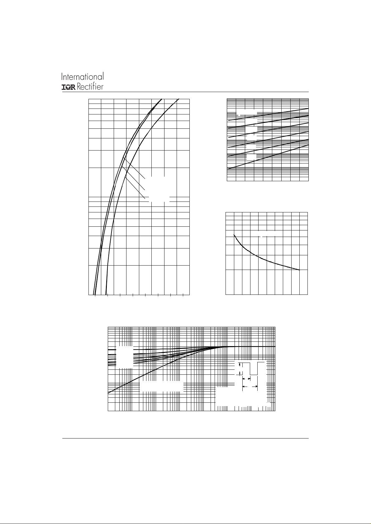
100
100
T = 150°C
10
J
125°C
R
1
0.1
100°C
75°C
50°C
0.01
F
T = 150°C
J
T = 125°C
10
J
T = 25°C
J
Reverse C urrent - I (m A )
0.001
0.0001
0 5 10 15 20 25 30 35 40 45
Fig. 2 - Typical Values Of Reverse Current
25°C
Re v er se Vo lta ge - V (V)
R
Vs. Reverse Voltage (Per Leg)
1000
Instanta neous Forward Current - I (A)
T
T = 25 °C
J
1
0.2 0.4 0.6 0.8 1 1.2 1.4 1.6 1.8
Fig. 1 - Max. Forward Voltage Drop Characteristics
www.irf.com
Jun ction Capacitance - C (pF)
100
0 1020304050
Forward Voltage Drop - V (V)
FM
Reverse Voltage - V (V)
Fig. 3 - Typical Junction Capacitance
(Per Leg)
Vs. Reverse Voltage (Per Leg)
10
D = 0.75
D = 0.50
1
thJC
Thermal Impedance Z (°C/W)
D = 0.33
D = 0.25
D = 0.20
0.1
Singl e Pulse
(Thermal Resistance)
Notes:
1. Duty factor D = t / t
2. Peak T = P x Z + T
0.01
0.00001 0.0001 0.001 0.01 0.1 1 10 100
t , Rectang ular Pulse Dura tion (Seconds)
Fig. 4 - Max. Thermal Impedance Z
1
Characteristics (Per Leg)
thJC
P
DM
t
1
t
2
1
J
DM
thJC
R
2
C
3
 Loading...