

Vishay MBR7..PbF Series Data Sheet
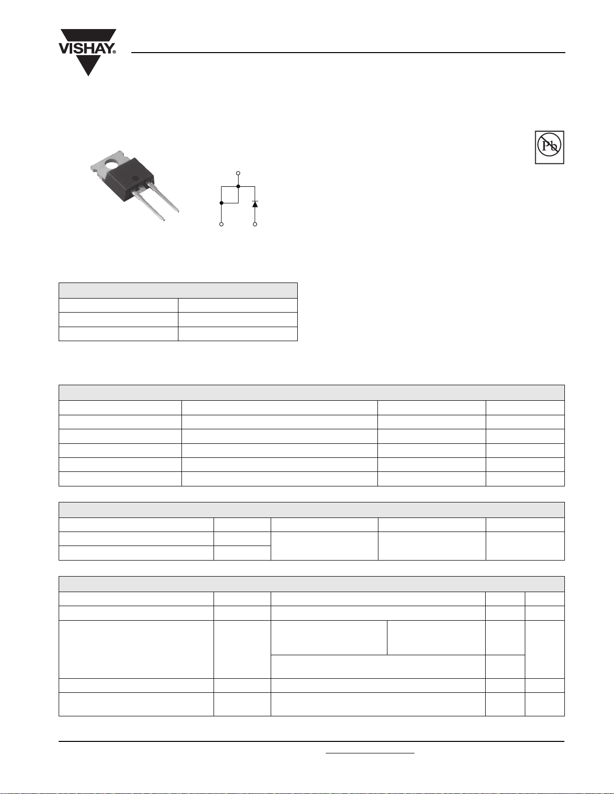
TO-220AC
Schottky Rectifier, 7.5 A
FEATURES
• 150 °C TJ operation
• High purity, high temperature epoxy
encapsulation for enhanced mechanical
strength and moisture resistance
• High frequency operation
• Low forward voltage drop
• Guard ring for enhanced ruggedness and long term
reliability
• Lead (Pb)-free (“PbF” suffix)
• Designed and qualified for industrial level
cathode
1
Cathode
Base
2
3
Anode
MBR7..PbF Series
Vishay High Power Products
Pb-free
Available
RoHS*
COMPLIANT
PRODUCT SUMMARY
I
F(AV)
V
R
I
RM
7.5 A
35 to 45 V
15 mA at 125 °C
DESCRIPTION
The MBR7..PbF Schottky rectifier has been optimized for low
reverse leakage at high temperature. The proprietary barrier
technology allows for reliable operation up to 150 °C junction
temperature. Typical applications are in switching power
supplies, converters, freewheeling diodes, and reverse
battery protection.
MAJOR RATINGS AND CHARACTERISTICS
SYMBOL CHARACTERISTICS VALUES UNITS
I
F(AV)
V
RRM
I
FSM
V
F
T
J
Rectangular waveform 7.5 A
35 to 45 V
tp = 5 µs sine 690 A
7.5 Apk, TJ = 125 °C 0.57 V
Range - 65 to 150 °C
VOLTAGE RATINGS
PARAMETER SYMBOL MBR735PbF MBR745PbF UNITS
Maximum DC reverse voltage V
Maximum working peak reverse voltage V
R
RWM
35 45 V
ABSOLUTE MAXIMUM RATINGS
PARAMETER SYMBOL TEST CONDITIONS VALUES UNITS
Maximum average forward current I
Non-repetitive peak surge current I
Non-repetitive avalanche energy E
Repetitive avalanche current I
* Pb containing terminations are not RoHS compliant, exemptions may apply
Document Number: 94299 For technical questions, contact: diodes-tech@vishay.com
Revision: 20-Aug-08 1
F(AV)
FSM
AS
AR
TC = 131 °C, rated V
5 µs sine or 3 µs rect. pulse
Surge applied at rated load condition half wave
single phase 60 Hz
TJ = 25 °C, IAS = 2 A, L = 3.5 mH 7 mJ
Current decaying linearly to zero in 1 µs
Frequency limited by T
R
Following any rated load
condition and with rated
V
applied
RRM
maximum VA = 1.5 x VR typical
J
7.5 A
690
150
2A
www.vishay.com
A
MBR7..PbF Series
Vishay High Power Products
Schottky Rectifier, 7.5 A
ELECTRICAL SPECIFICATIONS
PARAMETER SYMBOL TEST CONDITIONS VALUES UNITS
15 A TJ = 25 °C 0.84
Maximum forward voltage drop V
FM
(1)
15 A 0.72
Maximum instantaneous reverse current I
Maximum junction capacitance C
Typical series inductance L
RM
T
= 125 °C 15
J
VR = 5 VDC (test signal range 100 kHz to 1 MHz) 25 °C 400 pF
T
Measured from top of terminal to mounting plane 8.0 nH
S
TJ = 25 °C
(1)
Maximum voltage rate of change dV/dt Rated V
T
= 125 °C
J
Rated DC voltage
R
0.57
0.1
1000 V/µs
Note
(1)
Pulse width < 300 µs, duty cycle < 2 %
THERMAL - MECHANICAL SPECIFICATIONS
PARAMETER SYMBOL TEST CONDITIONS VALUES UNITS
Maximum junction temperature range T
Maximum storage temperature range T
Maximum thermal resistance,
junction to case
Typical thermal resistance,
case to heatsink
J
Stg
R
DC operation 3.0
thJC
R
thCS
Mounting surface, smooth and greased 0.50
Approximate weight
Mounting torque
minimum 6 (5)
maximum 12 (10)
Marking device Case style TO-220AC MBR745
- 65 to 150
- 65 to 175
2g
0.07 oz.
kgf · cm
(lbf · in)
V7.5 A
mA
°C
°C/W
www.vishay.com For technical questions, contact: diodes-tech@vishay.com
Document Number: 94299
2 Revision: 20-Aug-08
MBR7..PbF Series
Schottky Rectifier, 7.5 A
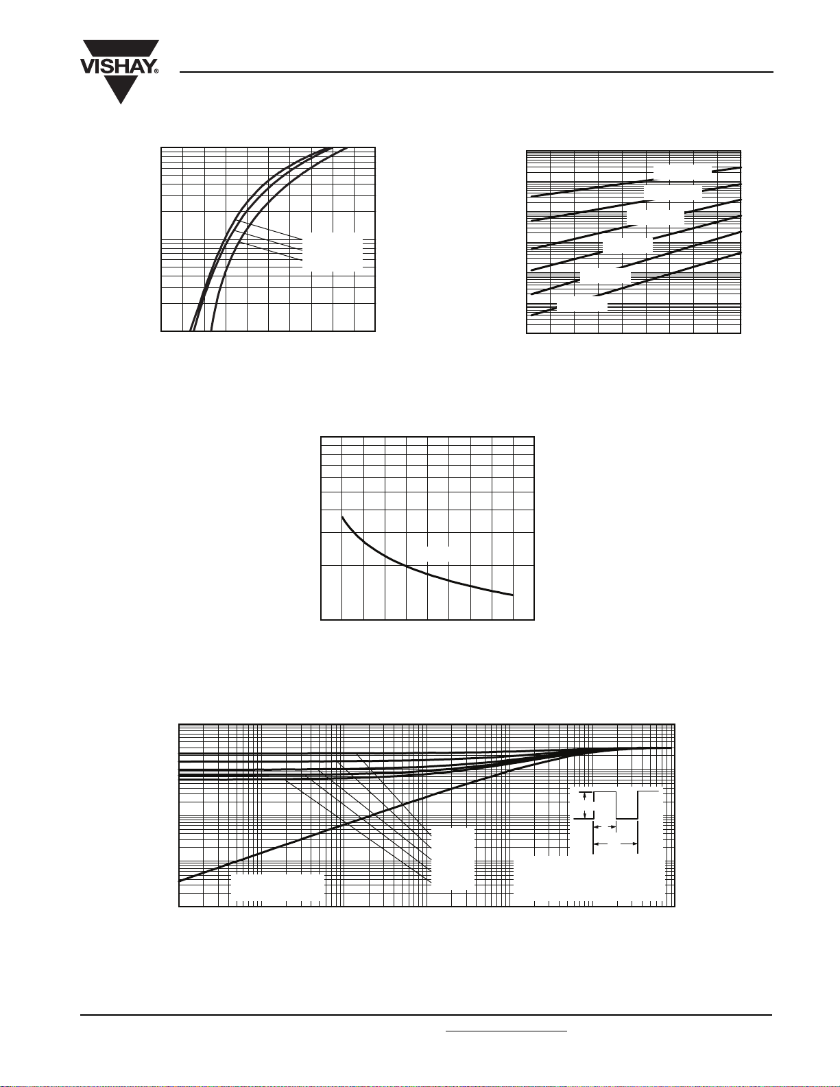
100
10
1
- Instantaneous Forward Current (A)
F
I
0 0.2 0.6 0.8 1.0
VFM - Forward Voltage Drop (V)
Fig. 1 - Maximum Forward Voltage Drop Characteristics
(Per Leg)
TJ = 150 °C
= 125 °C
T
J
= 25 °C
T
J
1.2 1.4 1.6 1.8
1000
Vishay High Power Products
100
10
1
0.1
0.01
- Reverse Current (mA)
R
0.001
I
2.00.4
0.0001
TJ = 25 °C
510 20 30 40
0
TJ = 75 °C
TJ = 50 °C
15 35 4525
VR - Reverse Voltage (V)
Fig. 2 - Typical Values of Reverse Current vs.
Reverse Voltage (Per Leg)
TJ = 150 °C
TJ = 125 °C
TJ = 100 °C
TJ = 25 °C
- Junction Capacitance (pF)
T
C
100
10 30 40
020 50
VR - Reverse Voltage (V)
Fig. 3 - Typical Junction Capacitance vs. Reverse Voltage (Per Leg)
10
1
0.1
D = 0.75
D = 0.50
0.01
- Thermal Impedance (°C/W)
thJC
Z
0.001
0.00001 0.0001 0.001 0.01 0.1
Single pulse
(thermal resistance)
D = 0.33
D = 0.25
D = 0.20
t1 - Rectangular Pulse Duration (s)
Fig. 4 - Maximum Thermal Impedance Z
Notes:
1. Duty factor D = t
2. Peak TJ = PDM x Z
Characteristics (Per Leg)
thJC
P
DM
t
1
t
2
.
1/t2
+ T
thJC
C
1 10
Document Number: 94299 For technical questions, contact: diodes-tech@vishay.com
www.vishay.com
Revision: 20-Aug-08 3
 Loading...