

Vishay MBR4060WT Data Sheet
Bulletin PD-20052 01/01
MBR4060WT
SCHOTTKY RECTIFIER
Major Ratings and Characteristics
Characteristics Values Units
I
Rectangular 40 A
F(AV)
waveform
V
RRM
I
@ tp = 5 µs sine 3200 A
FSM
VF@ 20 Apk, TJ=125°C 0.49 V
(per leg)
T
J
60 V
- 55 to 150 °C
40 Amp
I
= 40Amp
F(AV)
VR = 60V
Description/Features
The MBR... center tap Schottky rectifier has been optimized
for very low forward voltage drop, with moderate leakage. The
proprietary barrier technology allows for reliable operation up
to 150° C junction temperature. Typical applications are in
switching power supplies, converters, free-wheeling diodes,
and reverse battery protection.
150° C TJ operation
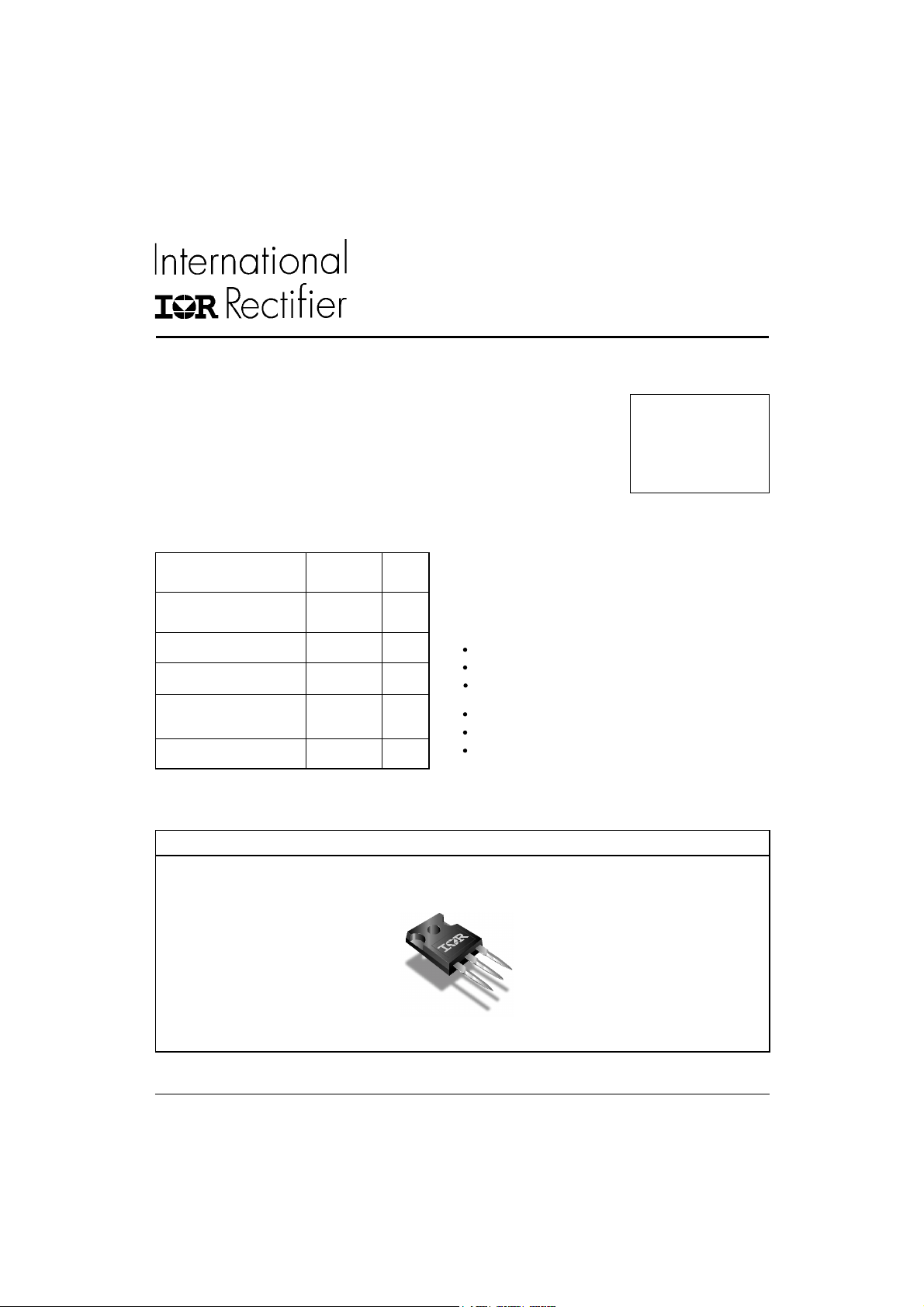
Center tap TO-247 package
High purity, high temperature epoxy encapsulation for
enhanced mechanical strength and moisture resistance
Very low forward voltage drop
High frequency operation
Guard ring for enhanced ruggedness and long term
reliability
www.irf.com
Case Styles
MBR4060WT
TO-247
1
MBR4060WT
Bulletin PD-20052 01/01
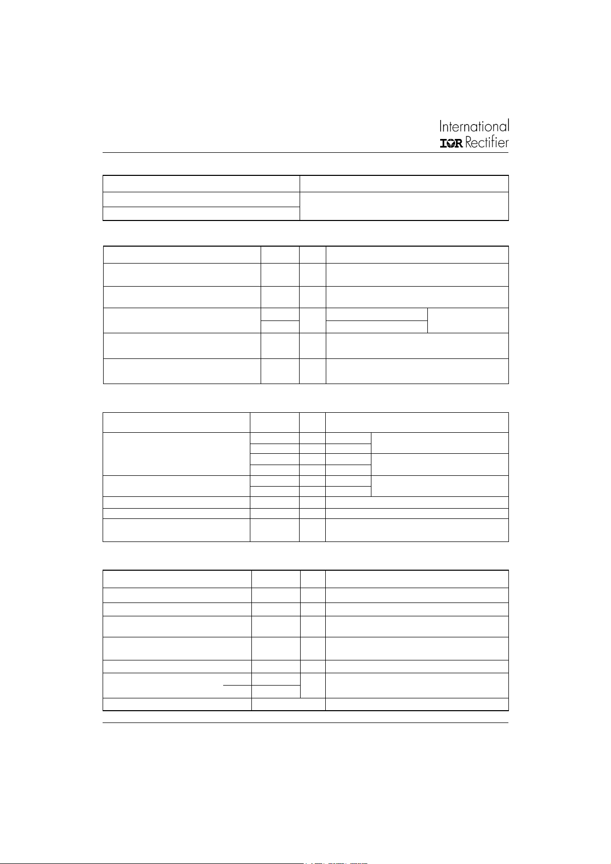
Voltage Ratings
Part number MBR4060WT
VRMax. DC Reverse Voltage (V)
V
Max. Working Peak Reverse Voltage (V)
RWM
60
Absolute Maximum Ratings
Parameters Values Units Conditions
I
Max. Average Forward 40 A @ TC = 120°C, 50% duty cycle, rectangular waveform
F(AV)
Current
I
Peak Repetitive Forward 40 A Rated VR , square wave, 20kHz
FRM
Current (Per Leg) TC = 125° C
I
Max.Peak One Cycle Non-Repetitive 3200 5µs Sine or 3µs Rect. pulse
FSM
Surge Current ( Per Leg) See fig.7 320 10ms Sine or 6ms Rect. pulse
EASNon-Repetitive Avalanche Energy 18 mJ TJ = 25 °C, I
A
= 3 Amps, L = 4.40 mH
AS
(Per Leg)
IARRepetitive Avalanche Current 2 A Current decaying linearly to zero in 1 µsec
(Per Leg) Frequency limited by T
Following any rated
load condition and with
rated V
max. VA = 1.5 x VR typical
J
RRM
applied
Electrical Specifications
Parameters Values Units Conditions
VFMMax. Forward Voltage Drop 0.53 V @ 20A
0.68 V @ 40A
(1) 0.49 V @ 20A
0.64 V @ 40A
IRMMax. Instantaneus Reverse Current 1.7 mA TJ = 25 °C Rated DC voltage
96 mA TJ = 125°C
CTMax. Junction Capacitance 900 pF VR = 5VDC, (test signal range 100Khz to 1Mhz) 25°C
LSTypical Series Inductance 7.5 nH Measured from top of terminal to mounting plane
dv/dt Max. Voltage Rate of Change 10000 V/ µs
(Rated VR)
TJ = 25 °C
TJ = 125 °C
(1) Pulse Width < 300µs, Duty Cycle <2%
Thermal-Mechanical Specifications
Parameters Values Units Conditions
TJMax. Junction Temperature Range -55 to 150 °C
T
Max. Storage Temperature Range -55 to 150 °C
stg
R
Max. Thermal Resistance 1.25 °C/W DC operation
thJC
Junction to Case (Per Package)
R
Typical Thermal Resistance 0.63 °C/W Mounting surface, smooth and greased
thCS
Case to Heatsink
wt Approximate Weight 6 (0.21) g (oz.)
T Mounting Torque Min. 6 (5)
Max. 12 (10)
Kg-cm
(Ibf-in)
Case Style TO-247AC (TO-3P) JEDEC
2
www.irf.com
 Loading...