

Vishay MBR4035PT, MBR4060PT Data Sheet
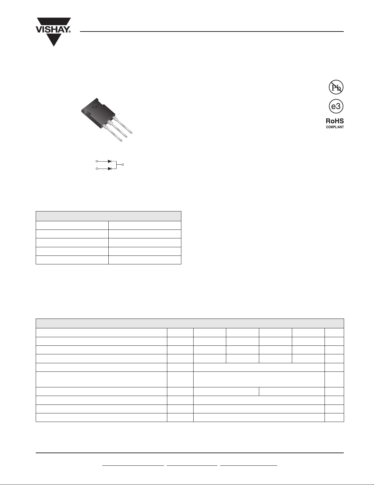
Dual Common-Cathode Schottky Rectifier
3
2
1
TO-247AD (TO-3P)
PIN 1
PIN 3
PRIMARY CHARACTERISTICS
I
F(AV)
V
RRM
I
FSM
V
F
T
max. 150 °C
J
PIN 2
CASE
35 V to 60 V
0.60 V, 0.62 V
40 A
400 A
MBR4035PT thru MBR4060PT
Vishay General Semiconductor
FEATURES
• Guardring for overvoltage protection
• Lower power losses, high efficiency
• Low forward voltage drop
• High forward surge capability
• High frequency operation
• Solder dip 260 °C, 40 s
• Component in accordance to RoHS 2002/95/EC
and WEEE 2002/96/EC
TYPICAL APPLICATIONS
For use in low voltage, high frequency rectifier of
switching mode power supplies, freewheeling diodes,
dc-to-dc converters or polarity protection application.
MECHANICAL DATA
Case: TO-247AD (TO-3P)
Epoxy meets UL 94V-0 flammability rating
Terminals: Matte tin plated leads, solderable per
J-STD-002 and JESD22-B102
E3 suffix for consumer grade, meets JESD 201 class
1A whisker test
Polarity: As marked
Mounting Torque: 10 in-lbs maximum
MAXIMUM RATINGS (TA = 25 °C unless otherwise noted)
PARAMETER SYMBOL MBR4035PT MBR4045PT MBR4050PT MBR4060PT UNIT
Maximum repetitive peak reverse voltage V
Maximum working peak reverse voltage V
Maximum DC blocking voltage V
Maximum average forward rectified current at T
Peak forward surge current, 8.3 ms single
half sine-wave superimposed on rated load per diode
Peak repetitive reverse surge current per diode
Voltage rate of change at (rated V
Operating junction temperature range T
Storage temperature range T
Note:
(1) 2.0 µs pulse width, f = 1.0 kHz
Document Number: 88679
Revision: 25-Mar-08
) dV/dt 10 000 V/µs
R
For technical questions within your region, please contact one of the following:
PDD-Americas@vishay.com
= 125 °C I
C
(1)
, PDD-Asia@vishay.com, PDD-Europe@vishay.com
35 45 50 60 V
RRM
35 45 50 60 V
RWM
35 45 50 60 V
DC
F(AV)
I
400 A
FSM
I
RRM
- 65 to + 150 °C
J
- 65 to + 175 °C
STG
2.0 1.0 A
40 A
www.vishay.com
1
MBR4035PT thru MBR4060PT
Vishay General Semiconductor
ELECTRICAL CHARACTERISTICS (TA = 25 °C unless otherwise noted)
PARAMETER TEST CONDITIONS SYMBOL MBR4035PT MBR4045PT MBR4050PT MBR4060PT UNIT
Maximum instantaneous
forward voltage per diode
Maximum instantaneous
reverse current at rated DC
blocking voltage per diode
(1)
(1)
IF = 20 A,
I
= 20 A,
F
I
= 40 A,
F
I
= 40 A,
F
T
= 25 °C
C
T
= 125 °C
C
T
= 25 °C
C
T
= 125 °C
C
TC = 25 °C
T
= 125 °C
C
V
F
I
R
0.70
0.60
0.80
0.75
1.0
100
Note:
(1) Pulse test: 300 µs pulse width, 1 % duty cycle
THERMAL CHARACTERISTICS (TA = 25 °C unless otherwise noted)
PARAMETER SYMBOL MBR4035PT MBR4045PT MBR4050PT MBR4060PT UNIT
Maximum thermal resistance from junction to case per diode R
1.2 °C/W
θJC
0.72
0.62
-
-
mA
V
ORDERING INFORMATION (Example)
PACKAGE PREFERRED P/N UNIT WEIGHT (g) PACKAGE CODE BASE QUANTITY DELIVERY MODE
TO-247AD MBR4045PT-E3/45 6.13 45 30/tube Tube
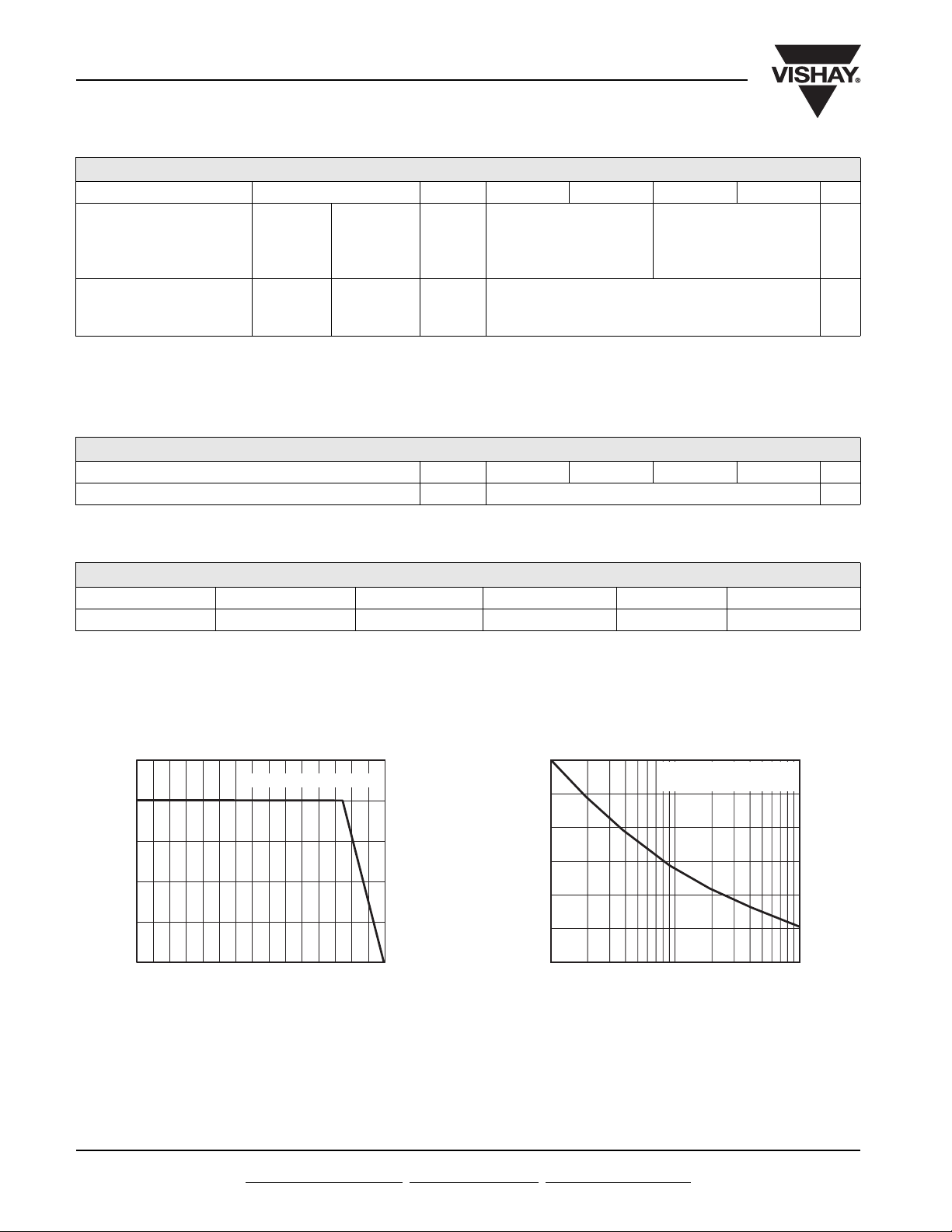
RATINGS AND CHARACTERISTICS CURVES
(T
= 25 °C unless otherwise noted)
A
50
Resistive or Inductive Load
40
30
20
10
Average Forward Current (A)
0
0
50
Case Temperature (°C)
Figure 1. Forward Current Derating Curve
100
150
400
300
200
Peak Fo rward Surge Current (A)
100
1
Number of Cycles at 60 Hz
TJ = TJ Max.
8.3 ms Single Half Sine-Wave
10
100
Figure 2. Maximum Non-Repetitive Peak Forward Surge
Current Per Diode
www.vishay.com For technical questions within your region, please contact one of the following:
2
PDD-Americas@vishay.com
, PDD-Asia@vishay.com, PDD-Europe@vishay.com
Document Number: 88679
Revision: 25-Mar-08
 Loading...