

KP 1830
Vishay Roederstein
AC and Pulse Film Foil Capacitors
KP Radial Potted Type
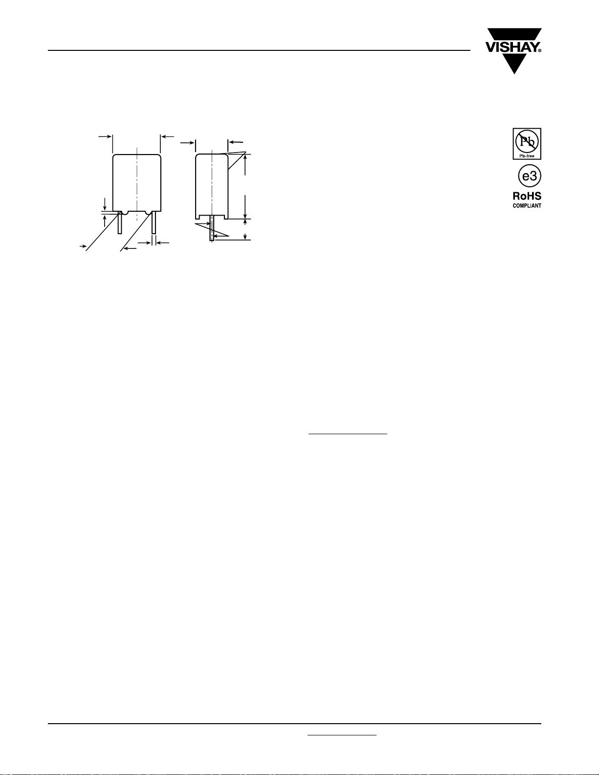
L max.
0.5
pcm
±
5.0 0.4
Dimensions in millimeters
Ø 0.5
W max.
±0.4
Marking
H
max.
-1
6.0
MAIN APPLICATIONS
Oscillator, timing and LC/RC filter circuits, high frequency
coupling of fast digital and analog IC’s.
REFERENCE STANDARDS
IEC 60384-13
MARKING
C-value; tolerance; rated voltage; sub-class; manufacturer’s
type; code for dielectric material; manufacturer’s location;
manufacturer’s logo; year and week
DIELECTRIC
Polypropylene film
FEATURES
5 mm lead pitch, supplied loose in box taped in
ammopack or reel
RoHS compliant
ENCAPSULATION
Plastic case, epoxy resin sealed, flame retardant
UL-class 94 V-0
CLIMATIC TESTING CLASS ACC. TO IEC 60068-1
55/100/56
CAPACITANCE RANGE
100 pF to 0.022 µF
CAPACITANCE TOLERANCE
± 10 % , ± 5 %, ± 2.5 %, ± 2 %, ± 1 %
LEADS
Tinned wire
MAXIMUM APLICATION TEMPERATURE
100 °C
DETAIL SPECIFICATION
For more detailed data and test requirements contact:
dc-film@vishay.com
ELECTRODES
Aluminum foil
CONSTRUCTION
Mono construction
RATED DC VOLTAGES
63 V, 250 V, 630 V
RATED AC VOLTAGES
40 V, 160 V, 250 V
www.vishay.com For technical questions, contact: dc-film@vishay.com
212 Revision: 16-Jan-09
Document Number: 26016
KP 1830
AC and Pulse Film Foil Capacitors
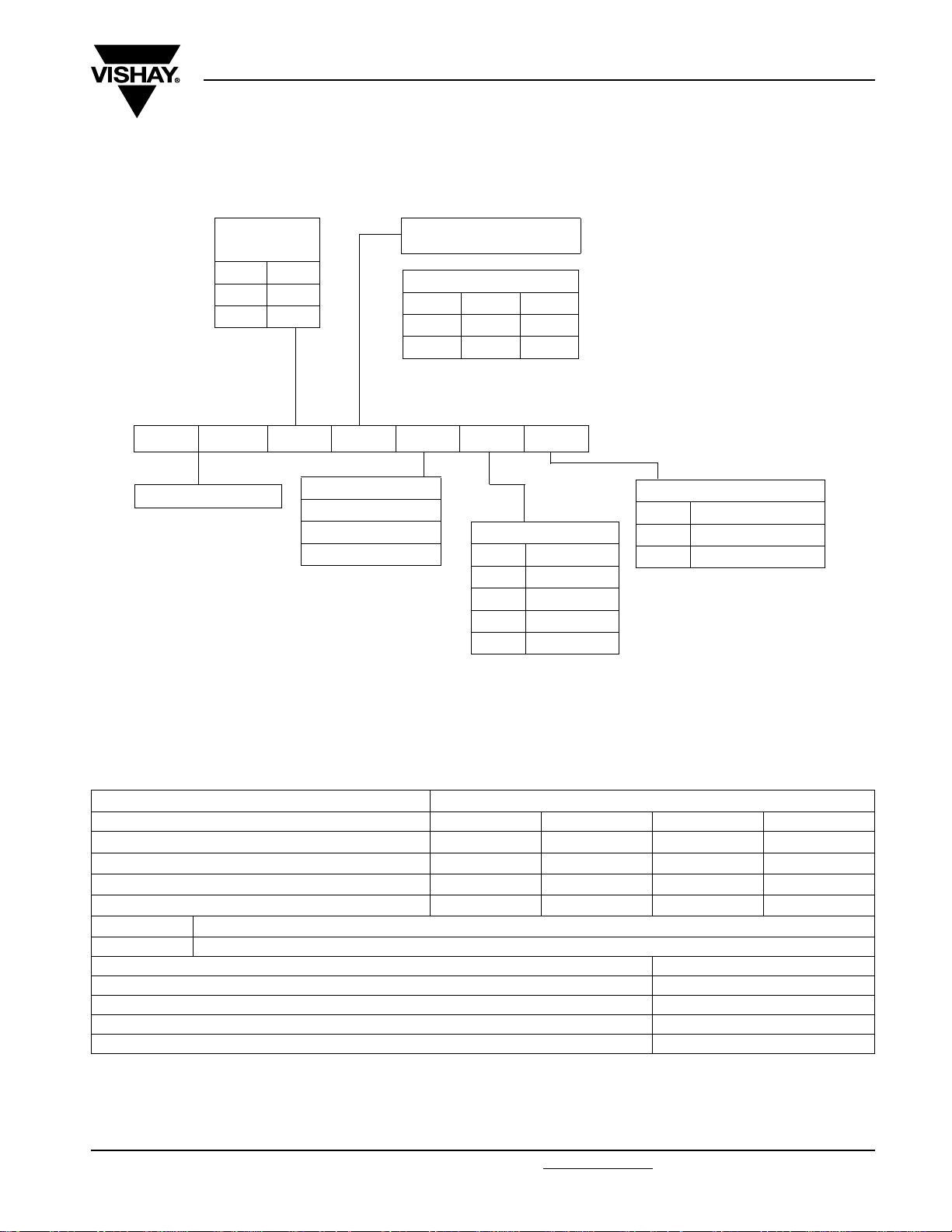
COMPOSITION OF CATALOG NUMBER
MULTIPLIER
(nF)
0.01 1
0.1 2
13
KP 1830 2 10 63 4 G
TYPE CONSTRUCTION
VOLTAGE CODE
06 = 63 Vdc
25 = 250 Vdc
63 = 630 Vdc
KP Radial Potted Type
CAPACITANCE
(numerically)
Example:
110 0.1 nF 100 pF
210 1.0 nF 1.0 nF
310 10 nF 10 nF
TOLERANCE CODE
1± 1 %
2± 2 %
3± 2.5 %
4± 5 %
5 ± 10 %
Vishay Roederstein
PACKAGING CODE
Bulk
G Ammo (H = 18.5)
W Reel (H = 18.5)
SPECIFIC REFERENCE DATA
DESCRIPTION VALUE
Tangent of loss angle: at 1 kHz at 10 kHz at 100 kHz at 1 MHz
C ≤ 1000 pF -
1000 pF < C ≤ 5000 pF
5000 pF < C ≤ 20 000 pF
20 000 pF < C < 33 000 pF
Pitch (mm)
5 > 10 000
R between leads, for C ≤ 0.33 µF at 100 V, 1 min > 500 000 MΩ
R between leads and case, 100 V, 1 min > 30 000 MΩ
Withstanding (DC) voltage (cut off current 10 mA), rise time 100 V/s 1.6 x U
Withstanding (DC) voltage between leads and case 2 x U
Maximum application temperature 100 °C
Document Number: 26016 For technical questions, contact: dc-film@vishay.com
Revision: 16-Jan-09 213
Maximum pulse rise time (dU/dt)
-
-
-
5 x 10
5 x 10
10 x 10
15 x 10
-4
-4
-4
-4
[V/µs]
R
-
10 x 10
15 x 10
25 x 10
-4
-4
-4
1 min
Rdc,
1 min
Rdc,
www.vishay.com
10 x 10
-
-
-
-4
KP 1830
Vishay Roederstein
AC and Pulse Film Foil Capacitors
KP Radial Potted Type
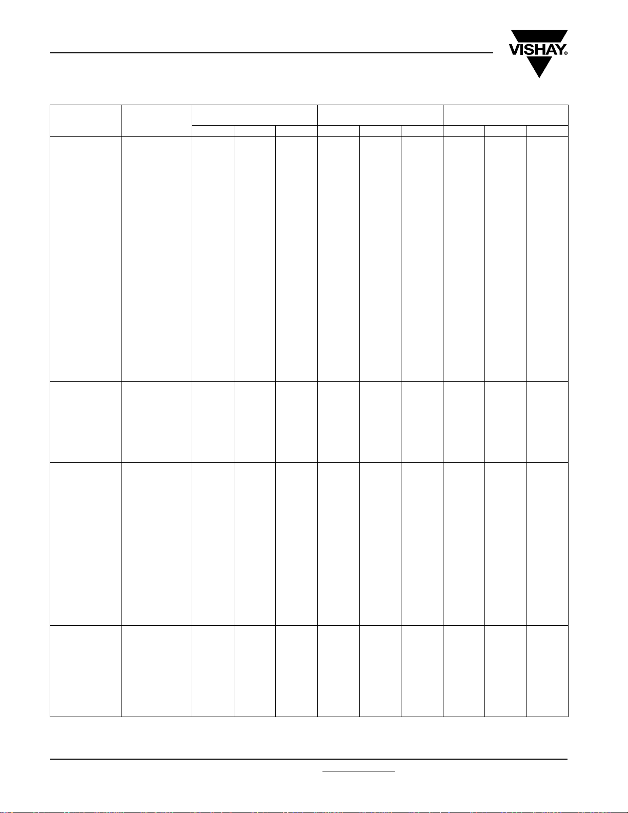
CAPACITANCE
100 pF -110 ------4.56.07.2
110 pF -111 ------4.56.07.2
120 pF -112 ------4.56.07.2
130 pF -113 ------4.56.07.2
150 pF -115 ------4.56.07.2
160 pF -116 ------4.56.07.2
180 pF -118 ------4.56.07.2
200 pF -120 ------4.56.07.2
220 pF -122 ------4.56.07.2
240 pF -124 ------4.56.07.2
270 pF -127 ------4.56.07.2
300 pF -130 ------4.56.07.2
330 pF -133 ------4.56.07.2
360 pF -136 ------4.56.07.2
390 pF -139 ------4.56.07.2
430 pF -143 ------4.56.07.2
470 pF -147 ------4.56.07.2
510 pF -151 ------4.56.07.2
560 pF -156 ------4.56.07.2
620 pF -162 ------4.56.07.2
680 pF -168 ------4.56.07.2
750 pF -175 ------4.56.07.2
820 pF -185 ------4.56.07.2
910 pF -191 ------4.56.07.2
1000 pF -210 ------4.56.07.2
1100 pF -211 ------4.56.07.2
1200 pF -212 ------4.56.07.2
1300 pF -213 ------4.56.07.2
1500 pF -215 ------4.56.07.2
1600 pF -216 ------4.56.07.2
1800 pF -218 ------4.56.07.2
2000 pF -220 - - - 4.5 6.0 7.2 5.5 7.0 7.2
2200 pF -222 - - - 4.5 6.0 7.2 5.5 7.0 7.2
2400 pF -224 4.5 6.0 7.2 4.5 6.0 7.2 5.5 7.0 7.2
2700 pF -227 4.5 6.0 7.2 4.5 6.0 7.2 5.5 7.0 7.2
3000 pF -230 4.5 6.0 7.2 5.5 7.0 7.2 5.5 7.0 7.2
3300 pF -233 4.5 6.0 7.2 5.5 7.0 7.2 5.5 7.0 7.2
3600 pF -236 4.5 6.0 7.2 5.5 7.0 7.2 7.5 7.0 7.2
3900 pF -239 4.5 6.0 7.2 5.5 7.0 7.2 7.5 9.0 7.2
4300 pF -243 4.5 6.0 7.2 5.5 7.0 7.2 7.5 9.0 7.2
4700 pF -247 4.5 6.0 7.2 5.5 7.0 7.2 7.5 9.0 7.2
5100 pF -251 4.5 6.0 7.2 7.5 9.0 7.2 7.5 9.0 7.2
5600 pF -256 4.5 6.0 7.2 7.5 9.0 7.2 7.5 9.0 7.2
6200 pF -262 4.5 6.0 7.2 7.5 9.0 7.2 7.5 9.0 7.2
6800 pF -268 4.5 6.0 7.2 7.5 9.0 7.2 7.5 9.0 7.2
7500 pF -275 5.5 7.0 7.2 7.5 9.0 7.2 9.0 10.0 7.2
8200 pF -282 5.5 7.0 7.2 7.5 9.0 7.2 9.0 10.0 7.2
9100 pF -291 5.5 7.0 7.2 7.5 9.0 7.2 9.0 10.0 7.2
0.01 µF -310 5.5 7.0 7.2 7.5 9.0 7.2 9.0 10.0 7.2
0.011 µF -311 5.5 7.0 7.2 9.0 10.0 7.2 - - -
0.012 µF -312 5.5 7.0 7.2 9.0 10.0 7.2 - - -
0.013 µF -313 5.5 7.0 7.2 9.0 10.0 7.2 - - -
0.015 µF -315 5.5 7.0 7.2 9.0 10.0 7.2 - - -
0.016 µF -316 9.0 10.0 7.2 - -----
0.018 µF -318 9.010.07.2------
0.020 µF -320 9.010.07.2------
0.022 µF -322 7.59.07.2------
Note
Further C-values upon request
CAPACITANCE
CODE
VOLTAGE CODE 06
63 Vdc/40 Vac
W H (mm) L (mm) W H (mm) L (mm) W H (mm) L (mm)
VOLTAGE CODE 25
250 Vdc/160 Vac
VOLTAGE CODE 63
630 Vdc/250 Vac
www.vishay.com For technical questions, contact: dc-film@vishay.com
214 Revision: 16-Jan-09
Document Number: 26016
KP 1830
AC and Pulse Film Foil Capacitors
Vishay Roederstein
KP Radial Potted Type
RECOMMENDED PACKAGING
LETTER
CODE
G Ammo 18.5 S
W Reel 18.5 350 KP 1830-310-065-W X
- Bulk - - KP 1830-310-065 X
Note
(1)
S = Box size 55 mm x 210 mm x 340 mm (W x H x L)
TYPE OF
PACKAGING
EXAMPLE OF ORDERING CODE
TYPE CAPACITANCE CODE VOLTAGE CODE TOLERANCE CODE PACKAGING CODE
KP 1830 210 63 1 G
Tolerance codes: 1 = 1 % (F); 2 = 2 % (G); 3 = 2.5 % (H); 4 = 5 % (J); 5 = 10 % (K)
Note
For detailed tape specifications refer to “Packaging Information” www.vishay.com/doc?28139
MOUNTING
Normal Use
The capacitors are designed for mounting on printed-circuit boards. The capacitors packed in bandoliers are designed for
mounting on printed-circuit boards by means of automatic insertion machines
For detailed tape specifications refer to “Packaging information” www.vishay.com/doc?28139 or end of catalog
HEIGHT (H)
(mm)
REEL DIAMETER
(mm)
(1)
.
ORDERING CODE
EXAMPLE
KP 1830-310-065-G X
or end of catalog
PITCH
5
Specific Method of Mounting of Withstand Vibration and Shock
In order to withstand vibration and shock tests, it must be ensured that the stand-off pips are in good contact with the
printed-circuit board.
• For pitches ≤ 15 mm the capacitors shall be mechanically fixed by the leads
• For larger pitches the capacitors shall be mounted in the same way and the body clamped
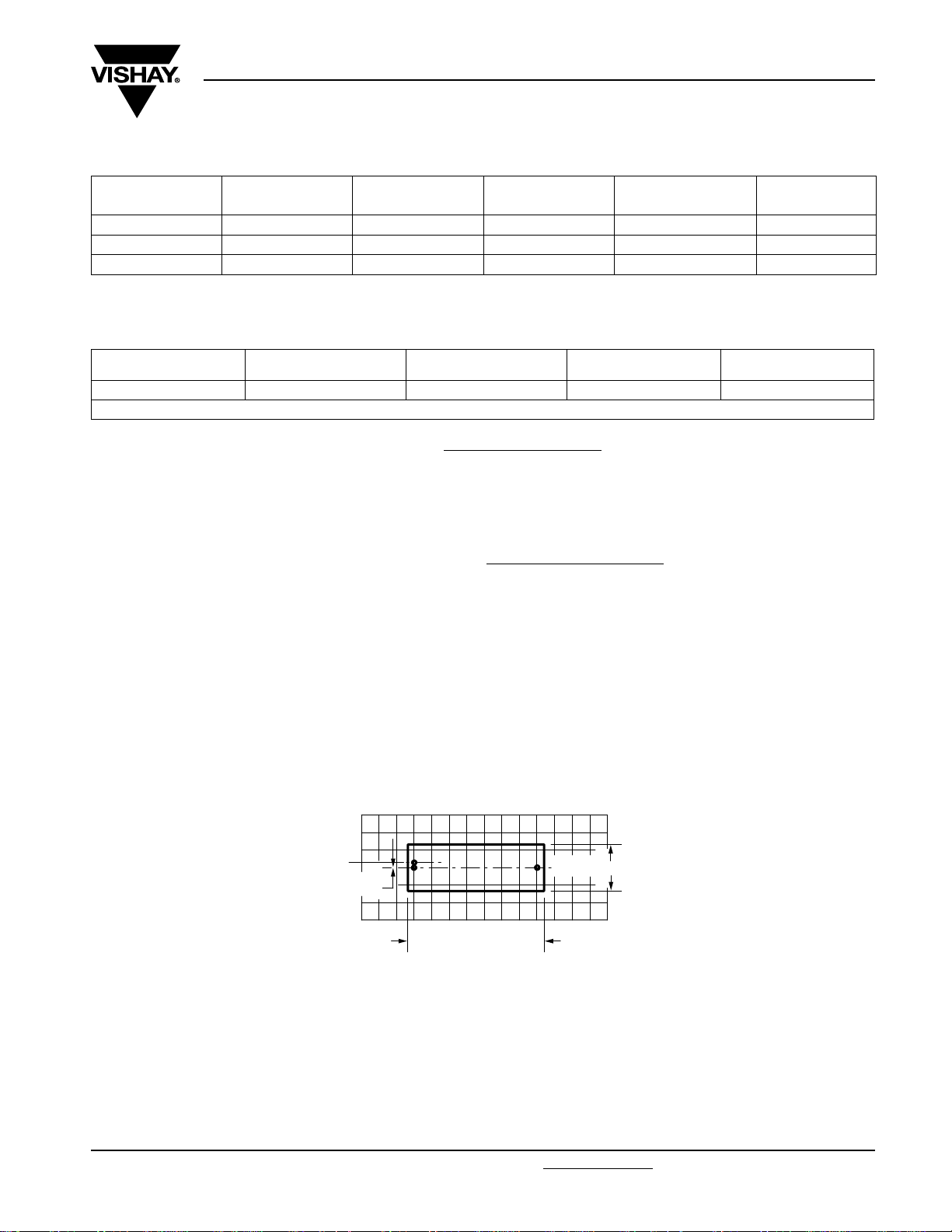
Space Requirements on Printed-Circuit Board
The maximum length and width of film capacitors is shown in the drawing:
• Eccentricity as in drawing. The maximum eccentricity is smaller than or equal to the lead diameter of the product concerned
• Product height with seating plane as given by “IEC 60717” as reference: h
Eccentricity
= I + 0.3 mm
I
max.
≤ h + 0.4 mm or h
max.
= b + 0.3 mm
b
max.
≤ h’ + 0.4 mm
max.
Storage Temperature
• Storage temperature: T
= - 25 °C to + 40 °C with RH maximum 80 % without condensation
stg
Ratings and Characteristics Reference Conditions
Unless otherwise specified, all electrical values apply to an ambient free temperature of 23 °C ± 1 °C, an atmospheric pressure
of 86 kPa to 106 kPa and a relative humidity of 50 % ± 2 %.
For reference testing, a conditioning period shall be applied over 96 h ± 4 h by heating the products in a circulating air oven at
the rated temperature and a relative humidity not exceeding 20 %.
Document Number: 26016 For technical questions, contact: dc-film@vishay.com
Revision: 16-Jan-09 215
www.vishay.com
KP 1830
Vishay Roederstein
AC and Pulse Film Foil Capacitors
KP Radial Potted Type
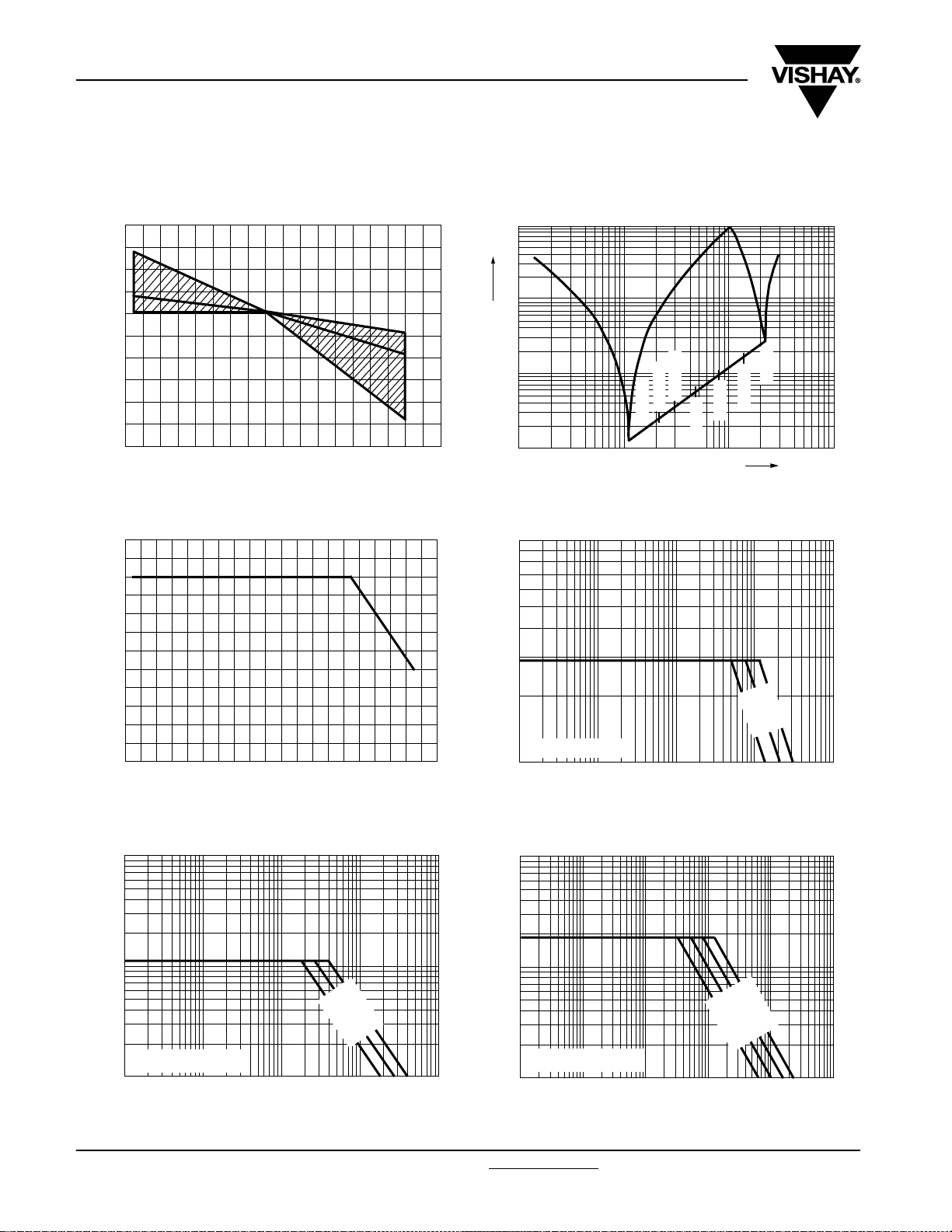
CHARACTERISTICS
Capacitance as a function of ambient temperature (typical curve) Impedance as a function of frequency (typical curve)
4
3
ΔC/C (%)
2
1
0
- 1
- 2
- 3
- 4
- 5
- 6
- 60 - 40 - 20
0
40 60 80
20
100 120
(°C)
T
amb
Max. DC and AC voltage as a function of temperature Max. RMS voltage as a function of frequency
1.2
10
Z (Ω)
1
0.1
4700 pF
0.001 µF
0.033 µF
0.01
1
10
Impedance versus Frequency Z = f (f) (Lead length 2.0 mm)
2
10
100
2200 pF
680 pF
220 pF
100 pF
f (MHz)
1000
1.0
factor
0.8
0.6
0.4
0.2
0.0
10
AC Voltage
10
(V)
AC Voltage
T
≤ 100 °C, 63 Vdc
amb
1
- 60
- 20 20 60 100
10
(°C)
T
amb
10
2
10
3
10
4
Max. RMS voltage as a function of frequency Max. RMS voltage as a function of frequency
3
(V)
2
2200 pF
4700 pF
0.01 µF
3
10
(V)
AC Voltage
2
10
0.015 µF
220 pF
470 pF
1000 pF
3300 pF
6800 p
F
5
10
100 pF
f (Hz)
T
10
10
≤ 100 °C, 250 Vdc
amb
1
2
10
3
10
4
5
f (Hz)
10
6
10
10
10
T
≤ 100 °C, 630 Vdc
amb
1
2
10
3
10
4
5
10
6
10
f (Hz)
7
10
www.vishay.com For technical questions, contact: dc-film@vishay.com
Document Number: 26016
216 Revision: 16-Jan-09
KP 1830
AC and Pulse Film Foil Capacitors
Vishay Roederstein
KP Radial Potted Type
HEAT CONDUCTIVITY (G) AS A FUNCTION OF ORIGINAL PITCH AND CAPACITOR BODY THICKNESS IN mW/°C
W
(mm)
max.
4.5 3
5.5 4
7.5 6
9.0 7
POWER DISSIPATION AND MAXIMUM COMPONENT TEMPERATURE RISE
The power dissipation must be limited in order not to exceed the maximum allowed component temperature rise as a function of
the free air ambient temperature.
The power dissipation can be calculated according type detail specification “HQN-384-01/101: Technical Information Film
Capacitors” with the typical tgd of the curves.
The component temperature rise (ΔT) can be measured (see section “Measuring the component temperature” for more details)
or calculated by ΔT = P/G:
ΔT = Component temperature rise (°C)
• P = Power dissipation of the component (mW)
• G = Heat conductivity of the component (mW/°C)
HEAT CONDUCTIVITY (mW/°C)
PITCH 5 mm
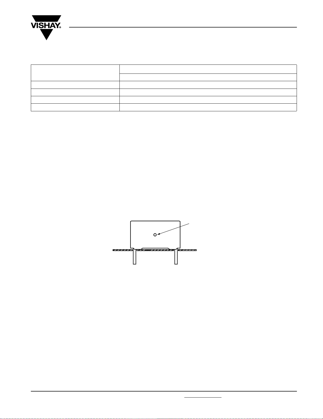
MEASURING THE COMPONENT TEMPERATURE
A thermocouple must be attached to the capacitor body as in:
Thermocouple
- T
) and maximum loaded condition (Tc).
amb
.
amb
The temperature is measured in unloaded (T
The temperature rise is given by ΔT = T
c
To avoid radiation or convection, the capacitor should be tested in a wind-free box.
APPLICATION NOTE AND LIMITING CONDITIONS
To select the capacitor for a certain application, the following conditions must be checked:
1. The peak voltage (U
2. The peak-to-peak voltage (U
3. The maximum component surface temperature rise must be lower than the limits
4. The maximum application temperature must be lower than 105 °C
5. There is no limit for the voltage pulse slope in the application
) shall not be greater than the rated DC voltage (U
p
) shall not be greater than the maximum (U
p-p
)
Rdc
) to avoid the ionisation inception level
p-p
Document Number: 26016 For technical questions, contact: dc-film@vishay.com
Revision: 16-Jan-09 217
www.vishay.com
KP 1830
Vishay Roederstein
AC and Pulse Film Foil Capacitors
KP Radial Potted Type
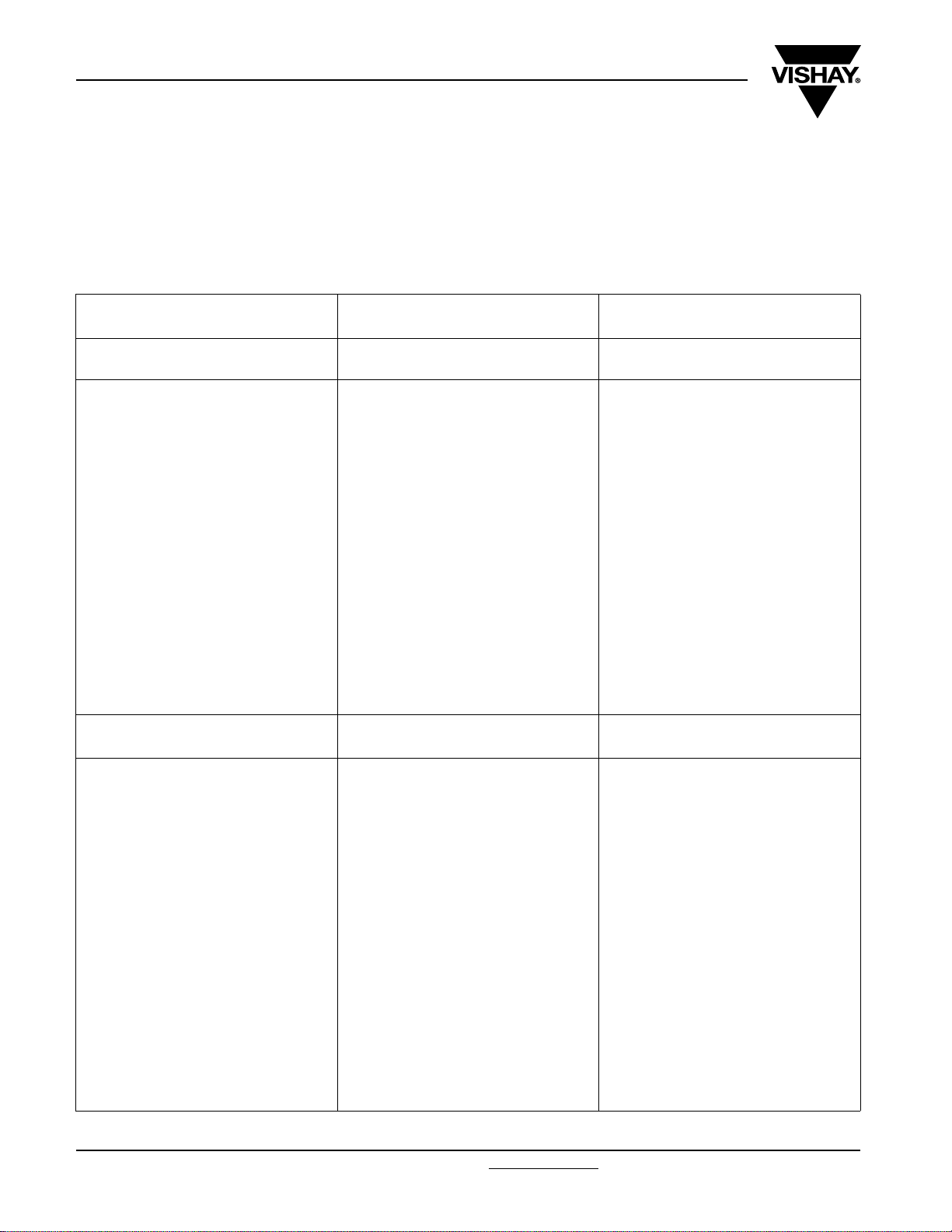
INSPECTION REQUIREMENTS
General Notes:
Sub-clause numbers of tests and performance requirements refer to the “Sectional Specification, Publication IEC 60384-13 and
Specific Reference Data”.
Group C Inspection Requirements
SUB-CLAUSE NUMBER AND TEST CONDITIONS PERFORMANCE REQUIREMENTS
SUB-GROUP C1A PART OF SAMPLE
OF SUB-GROUP C1
4.1 Dimensions (detail) As specified in chapters “General Data” of
this specification
4.3.1 Initial measurements Capacitance at 1 kHz
4.3 Robustness of terminations Tensile: Load 10 N; 10 s
4.4 Resistance to soldering heat No predrying
4.14 Component solvent resistance Isopropylalcohol at room temperature
4.4.2 Final measurements Visual examination No visible damage
Tangent of loss angle at 100 kHz
No visible damage
Bending: Load 5 N; 4 x 90°
Method: 1A
Solder bath: 280 °C ± 5 °C
Duration: 5 s
Method: 2
Immersion time: 5.0 min ± 0.5 min
Recovery time: Min. 1 h, max. 2 h
Legible marking
Capacitance |ΔC/C| ≤ 2 % of the value measured in 4.3.1
SUB-GROUP C1B PART OF SAMPLE
OF SUB-GROUP C1
4.6.1 Initial measurements Capacitance at 1 kHz
4.14 Solvent resistance of the marking
4.6 Rapid change of temperature θA = - 55 °C
4.7 Vibration Visual examination
www.vishay.com For technical questions, contact: dc-film@vishay.com
218 Revision: 16-Jan-09
Tangent of loss angle at 100 kHz
Isopropylalcohol at room temperature
Method: 1
Rubbing material: cotton wool
Immersion time: 5.0 min ± 0.5 min
θB = + 105 °C
5 cycles
Duration t = 30 min
Mounting:
See section “Mounting” of this specification
Procedure B4
Frequency range: 10 Hz to 55 Hz
Amplitude: 0.75 mm or
Acceleration 98 m/s²
(whichever is less severe)
Total duration 6 h
No visible damage
Legible marking
No visible damage
Document Number: 26016

KP 1830
AC and Pulse Film Foil Capacitors
Vishay Roederstein
KP Radial Potted Type
SUB-CLAUSE NUMBER AND TEST CONDITIONS PERFORMANCE REQUIREMENTS
4.7.2 Final inspection Visual examination
4.9 Shock Mounting:
4.9.3 Final measurements Visual examination No visible damage
SUB-GROUP C1 COMBINED SAMPLE
OF SPECIMENS OF SUB-GROUPS
C1A AND C1B
4.10 Climatic sequence
4.10.2 Dry heat Temperature: + 100 °C
4.10.3 Damp heat cyclic
Test Db, first cycle
4.10.4 Cold Temperature: - 55 °C
4.10.6 Damp heat cyclic
Test Db, remaining cycles
4.10.6.2 Final measurements Voltage proof = U
Capacitance
Tangent of loss angle As specified in section “Tangent of loss
See section “Mounting” of this specification
Pulse shape: Half sine
Acceleration: 490 m/s²
Duration of pulse: 11 ms
Capacitance |ΔC/C| ≤ 2 % of the value measured in 4.6.1.
Duration: 16 h
Duration: 2 h
Recovery 1 h to 2 h
for 1 min within 15 min
after removal from testchamber
Visual examination No visible damage
Capacitance |ΔC/C| ≤ 2 % of the value measured in
Tangent of loss angle As specified in section “Tangent of loss
Rdc
No visible damage
|ΔC/C| ≤ 2 % of the value measured in 4.6.1
angle” of this specification
No breakdown of flash-over
Legible marking
4.10.2
angle” of this specification or ≤ 1.4 times the
value measured in 4.3.1 whichever is greater
Insulation resistance
SUB-GROUP C2
4.11 Damp heat steady state
4.11.1 Initial measurements Capacitance at 1 kHz
4.11.3 Final measurements Visual examination No visible damage
Document Number: 26016 For technical questions, contact: dc-film@vishay.com
Revision: 16-Jan-09 219
Tangent of loss angle at 1 kHz
Voltage proof = U
after removal from testchamber
Capacitance |ΔC/C| ≤ 1 % of the value measured in
Tangent of loss angle
Insulation resistance ≥ 50 % of values specified in section
for 1 min within 15 min
Rdc
≥ 50 % of values specified in section
“Insulation resistance” of this specification
No breakdown of flash-over
Legible marking
4.11.1.
As specified in section “Tangent of loss
angle” of this specification or ≤ 1.4 times the
value measured in 4.11.1whichever is
greater
“Insulation resistance” of this specification
www.vishay.com
KP 1830
Vishay Roederstein
AC and Pulse Film Foil Capacitors
KP Radial Potted Type
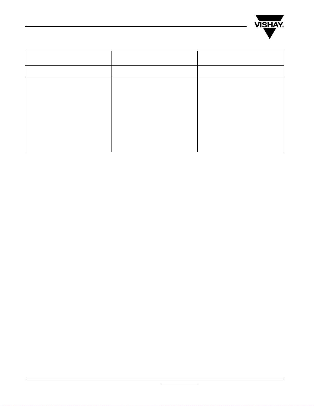
SUB-CLAUSE NUMBER AND TEST CONDITIONS PERFORMANCE REQUIREMENTS
SUB GROUP C3
4.12 Endurance Duration: 2000 h
4.12.1 Initial measurements Capacitance at 1 kHz
4.12.5 Final measurements Visual examination No visible damage
1.5 x U
1.05 x U
Tangent of loss angle at 100 kHz
Capacitance
Tangent of loss angle
Insulation resistance As specified in section “Insulation
at 85 °C
Rdc
Rdc
at 100 °C
Legible marking
|ΔC/C| ≤ 2 % of the value measured in 4.12.1
As specified in section “Tangent of loss
angle” of this specification or ≤ 1.4 times the
value measured in 4.12.1 whichever is
greater
resistance” of this specification
www.vishay.com For technical questions, contact: dc-film@vishay.com
220 Revision: 16-Jan-09
Document Number: 26016

Legal Disclaimer Notice
Vishay
Disclaimer
All product specifications and data are subject to change without notice.
Vishay Intertechnology, Inc., its affiliates, agents, and employees, and all persons acting on its or their behalf
(collectively, “Vishay”), disclaim any and all liability for any errors, inaccuracies or incompleteness contained herein
or in any other disclosure relating to any product.
Vishay disclaims any and all liability arising out of the use or application of any product described herein or of any
information provided herein to the maximum extent permitted by law. The product specifications do not expand or
otherwise modify Vishay’s terms and conditions of purchase, including but not limited to the warranty expressed
therein, which apply to these products.
No license, express or implied, by estoppel or otherwise, to any intellectual property rights is granted by this
document or by any conduct of Vishay.
The products shown herein are not designed for use in medical, life-saving, or life-sustaining applications unless
otherwise expressly indicated. Customers using or selling Vishay products not expressly indicated for use in such
applications do so entirely at their own risk and agree to fully indemnify Vishay for any damages arising or resulting
from such use or sale. Please contact authorized Vishay personnel to obtain written terms and conditions regarding
products designed for such applications.
Product names and markings noted herein may be trademarks of their respective owners.
Document Number: 91000 www.vishay.com
Revision: 18-Jul-08 1
 Loading...