

Page 1
www.DataSheet4U.com
PATENTED
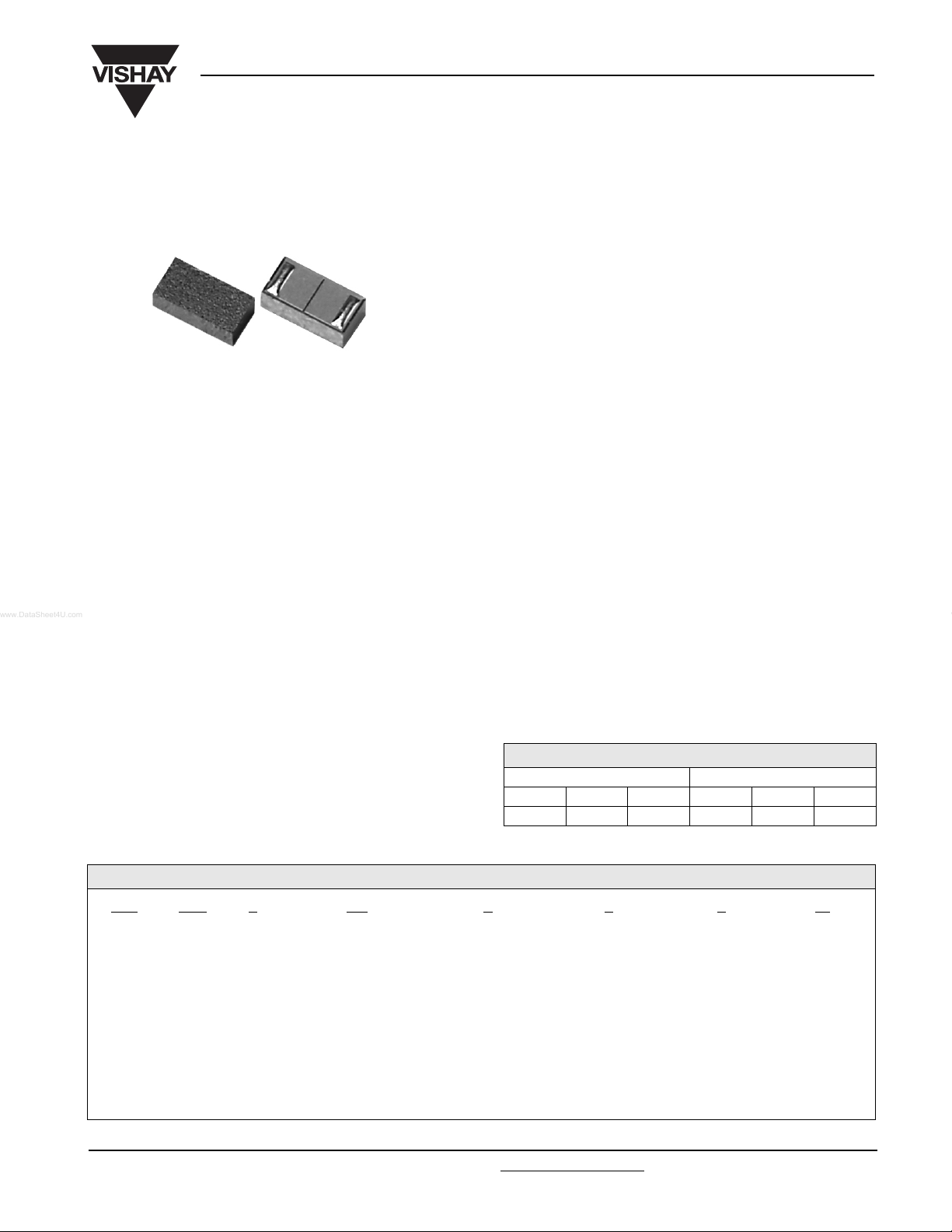
HPC0603A
Vishay
High Performance, High Precision
Surface Mount 0603 Capacitor
FEATURES
• New technology surface mount capacitor based on a
special semiconductor process
• Construction reduces the parasitic inductance and brings
the SRF values to ultra-high frequencies
• Capacitance is extremely stable in a wide range of
frequencies from 1 MHz to several GHz.
• High Q and low ESR
• Tight tolerance to ± 1 % or 0.05 pF
• Ultra high SRF
• Low parasitic inductance ( ~ 0.046 nH)
• Capacitance range : 0.8 pF to 560 pF
ELECTRICAL SPECIFICATIONS
Operating Temperature: - 55 °C to + 125 °C
Temperature Coefficient
of Capacitance (TCC): 0 ± 30 ppm/°C
Insulation Resistance: 10
Voltage: 2.5 x rated voltage for 5 seconds
Ageing: none
11
Ω min
APPLICATIONS
• Wireless communications
• Mobile phones
• Cordless phones
• GPS
• VCO
• Filter Networks
• Matching Networks
• Base station
ENVIRONMENTAL SPECIFICATIONS
Life Test: 1000 hours, + 125 °C at
• DC Blocking
• High speed circuitry
2 x rated voltage
Thermal Shock: 100 Cycles, - 55 °C/+ 125 °C
Moisture Resistance: 240 hours, 85 % RH, + 85 °C
CAPACITANCE TOLERANCE CODE
FOR LESS THAN 10 pF FOR 10 pF AND HIGHER
ABCFGJ
± 0.05 pF ± 0.10 pF ± 0.25 pF ± 1 % ± 2 % ± 5 %
ORDERING INFORMATION
HPC 0603 A 100 G X X T5
MODEL SIZE TYPE CAPACITANCE VALUE CAPACITANCE
TOLERANCE
TERMINATION VOLTAGE PACKAGING
The first two digits are
significant, the third is a
multiplier. An “R”
indicates a decimal point.
Examples: 101 = 100 pF
4R7 = 4.7 pF
Document Number: 10137 For technical questions, contact siliconRFcap@vishay.com
Revision: 22-Dec-04 15
see chart above X = Tin/Lead
termination
W = Lead (Pb)-free
termination
1 = 6 V
Z = 10 V
Y = 16 V
X = 25 V
M = 50 V
T5 = 5000 pcs
tape and reel
T1 = 1000 pcs
tape and reel
www.vishay.com
Page 2
HPC0603A
Vishay
High Performance, High Precision
Surface Mount 0603 Capacitor
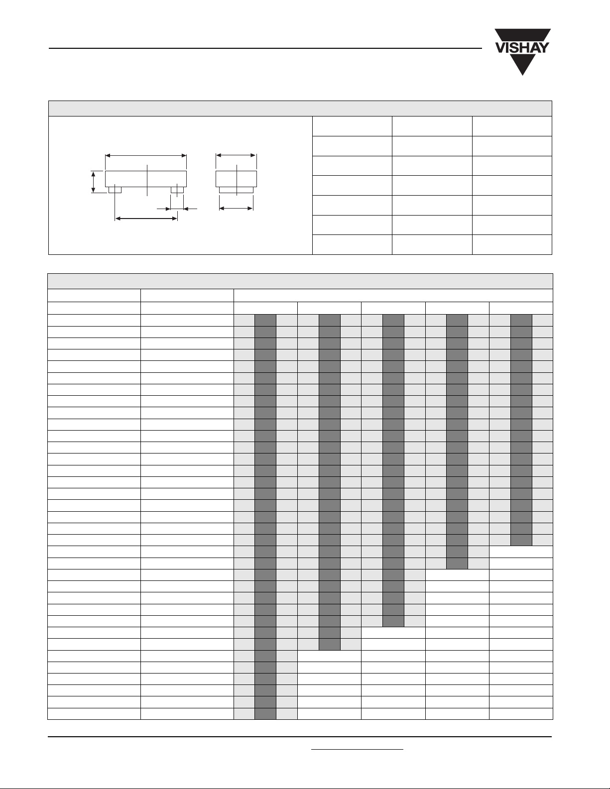
DIMENSIONS
DIMENSION INCHES MILLIMETERS
L
T
A
B
For PAD DESIGN, please see assembly/reflow recommendations page 21.
W
C
CAPACITANCE RANGE AND VOLTAGE
CAPACITANCE (pF) CAPACITANCE CODE VOLTAGE (V)
610162550
0.8 0R8
1.0 1RO
1.2 1R2
1.5 1R5
1.8 1R8
2.2 2R2
2.7 2R7
3.3 3R3
3.9 3R9
4.7 4R7
5.6 5R6
6.8 6R8
8.2 8R2
10 100
12 120
15 150
18 180
22 220
27 270
33 330
39 390
47 470
56 560
68 680
82 820
100 101
120 121
150 151
180 181
220 221
270 271
330 331
390 391
470 471
560 561
L 0.063 ± 0.002 1.60 ± 0.05
W 0.031 ± 0.002 0.80 ± 0.05
T 0.022 ± 0.002 0.56 ± 0.05
A 0.008 ± 0.002 0.20 ± 0.05
B 0.049 ± 0.002 1.24 ± 0.05
C 0.025 ± 0.002 0.64 ± 0.05
www.vishay.com For technical questions, contact siliconRFcap@vishay.com Document Number: 10137
16 Revision: 22-Dec-04
Page 3

HPC0603A
High Performance, High Precision
Vishay
Surface Mount 0603 Capacitor
ELECTRICAL SPECIFICATIONS*
CAPACITANCE (pF)
AT 1 M H z
0.8 A,B,C 26.4 0.80 6813 0.80 1491 0.80 519 0.80 174 0.81 124
1 A,B,C 23.6 1.00 5826 1.00 1275 1.00 443 1.01 148 1.01 105
1.2 A,B,C 21.5 1.20 5232 1.20 1145 1.20 398 1.21 133 1.22 95
1.5 A,B,C 19.2 1.50 4724 1.50 1033 1.50 359 1.52 120 1.53 85
1.8 A,B,C 17.6 1.80 4465 1.80 977 1.81 339 1.82 113 1.84 80
2.2 A,B,C 15.9 2.20 3947 2.20 863 2.21 300 2.24 100 2.26 70
2.7 A,B,C 14.3 2.70 3480 2.70 761 2.71 264 2.75 88 2.78 62
3.3 A,B,C 13.0 3.30 4157 3.30 909 3.32 315 3.38 104 3.43 73
3.6 A,B,C 12.4 3.60 3810 3.61 833 3.62 289 3.70 95 3.75 67
3.9 A,B,C 11.9 3.90 3517 3.91 769 3.93 266 4.01 88 4.08 62
4.3 A,B,C 11.4 4.30 3190 4.31 697 4.33 241 4.44 79 4.52 56
4.7 A,B,C 10.9 4.70 2918 4.71 638 4.74 221 4.86 72 4.96 51
5.1 A,B,C 10.4 5.10 2689 5.11 587 5.15 203 5.29 66 5.41 46
5.6 A,B,C 10.0 5.60 2449 5.61 535 5.66 185 5.84 60 5.98 42
6.2 B,C 9.5 6.20 2212 6.22 483 6.27 167 6.49 54 6.66 38
6.8 B,C 9.0 6.80 2017 6.82 440 6.88 152 7.15 49 7.36 34
7.5 B,C 8.6 7.50 1828 7.53 399 7.60 138 7.93 44 8.19 31
8.2 B,C 8.2 8.20 1672 8.23 365 8.32 126 8.71 40 9.03 28
9.1 B,C 7.8 9.11 1507 9.14 329 9.25 113 9.74 36 10.14 25
10 F,G,J 7.5 10.0 1371 10.0 299 10.2 103 10.8 33 11.3 22
11 F,G,J 7.1 11.0 1246 11.1 272 11.2 93 11.9 29 12.6 20
12 F,G,J 6.8 12.0 1142 12.1 249 12.3 85 13.1 27 13.9 18
13 F,G,J 6.5 13.0 1054 13.1 230 13.3 79 14.3 25 15.2 16
15 F,G,J 6.1 15.0 914 15.1 199 15.4 68 16.8 21 18.0 14
16 F,G,J 5.9 16.0 857 16.1 186 16.5 63 18.1 19 19.5 13
18 F,G,J 5.6 18.0 761 18.1 165 18.6 56 20.7 17 22.6 11
20 F,G,J 5.3 20.0 685 20.2 149 20.7 50 23.4 15 25.8 10
22 F,G,J 5.0 22.0 623 22.2 135 22.9 46 26.1 13 29.2 9
24 F,G,J 4.8 24.0 571 24.3 124 25.1 42 29.0 12 32.9 8
27 F,G,J 4.5 27.1 507 27.3 110 28.4 37 33.5 11 38.8 6
30 F,G,J 4.3 30.1 456 30.4 99 31.7 33 38.3 9 45.3 6
33 F,G,J 4.1 33.1 415 33.5 90 35.1 30 43.3 8 52.5 5
36 F,G,J 3.9 36.1 380 36.6 82 38.5 27 48.6 7 60.5 4
39 F,G,J 3.8 39.1 351 39.7 76 41.9 25 54.2 6 69.5 4
43 F,G,J 3.6 43.1 318 43.8 68 46.6 22 62.3 6 83.3 3
47 F,G,J 3.4 47.2 291 48.0 63 51.3 20 71.0 5 99.7 3
51 F,G,J 3.3 51.2 268 52.2 58 56.2 19 80.6 4 119.7 2
56 F,G,J 3.1 56.2 244 57.4 52 62.3 17 93.8 4 151.4 2
62 F,G,J 3.0 62.2 220 63.8 47 69.8 15 112.0 3 205.0 1
68 F,G,J 2.9 68.2 201 70.1 43 77.5 13 133.2 3 289.5 1
75 F,G,J 2.7 75.4 182 77.6 39 86.7 12 163.1 2 480.3 1
82 F,G,J 2.6 82.5 166 85.1 35 96.2 11 200.2 2
91 F,G,J 2.5 91.6 150 94.9 32 108.8 10 264.0 1
100 F,G,J 2.4 100.7 136 104.7 29 122.0 9 357.3 1
110 F,G,J 2.2 110.9 124 115.7 26 137.2 8 529.1 1
120 F,G,J 2.2 121.0 113 126.9 24 153.1 7
130 F,G,J 2.1 131.2 105 138.1 22 169.7 6
150 F,G,J 1.9 151.6 90 160.9 19 205.5 5
160 F,G,J 1.9 161.9 85 172.4 17 224.7 5
180 F,G,J 1.8 182.4 75 195.9 15 266.7 4
200 F,G,J 1.7 202.9 68 219.8 14 312.5 3
220 F,G,J 1.6 223.5 61 244.2 12 364.3 3
240 F,G,J 1.5 244.2 56 269.1 11 422.6 2
270 F,G,J 1.4 275.4 50 307.3 10 525.4 2
300 F,G,J 1.4 306.6 45 346.8 9 652.3 2
330 F,G,J 1.3 338.0 41 387.6 8 812.9 1
360 F,G,J 1.2 369.6 37 429.6 7 1022.9 1
390 F,G,J 1.2 401.3 34 473.0 6 1309.1 1
430 F,G,J 1.1 443.7 31 533.2 6 1903.4 1
470 F,G,J 1.1 486.5 28 596.1 5
510 F,G,J 1.0 529.4 26 661.9 5
560 F,G,J 1.0 583.5 24 748.7 4
Document Number: 10137 For technical questions, contact siliconRFcap@vishay.com
Revision: 22-Dec-04 17
TOLERANCE
CODE**
SRF (GHz)
TYP.
Ceff
TYP.
QCeff
TYP.
200 MHz 500 MHz 1000 MHz 2000 MHz 2500 MHz
QCeff
TYP.
QCeff
TYP.
QCeff
TYP.
www.vishay.com
Q
Page 4

HPC0603A
Vishay
High Performance, High Precision
SRF VS. CAPACITANCE (TYPICAL)
100
10
SRF (GHz)
1
0
0,1 1 10 100 1000
ESR VS. FREQUENCY (TYPICAL)
Surface Mount 0603 Capacitor
CAPACITANCE (pF)
1
1pF
2.2pF
10pF ; 100pF
0,1
ESR (ohm)
0,01
0 500 1000 1500 2000 2500 3000 3500
3.3pF
Q VS. FREQUENCY (TYPICAL)
10000
1000
100
Q factor
10
FREQUENCY (mHz)
1pF
10pF
100pF
1
0 500 1000 1500 2000 2500
FREQUENCY (MHz)
3000
www.vishay.com For technical questions, contact siliconRFcap@vishay.com Document Number: 10137
18 Revision: 22-Dec-04
Page 5

Legal Disclaimer Notice
Vishay
Notice
Specifications of the products displayed herein are subject to change without notice. Vishay Intertechnology, Inc.,
or anyone on its behalf, assumes no responsibility or liability for any errors or inaccuracies.
Information contained herein is intended to provide a product description only. No license, express or implied, by
estoppel or otherwise, to any intellectual property rights is granted by this document. Except as provided in Vishay's
terms and conditions of sale for such products, Vishay assumes no liability whatsoever, and disclaims any express
or implied warranty, relating to sale and/or use of Vishay products including liability or warranties relating to fitness
for a particular purpose, merchantability, or infringement of any patent, copyright, or other intellectual property right.
The products shown herein are not designed for use in medical, life-saving, or life-sustaining applications.
Customers using or selling these products for use in such applications do so at their own risk and agree to fully
indemnify Vishay for any damages resulting from such improper use or sale.
Document Number: 91000 www.vishay.com
Revision: 08-Apr-05 1
 Loading...