

PD -2.531
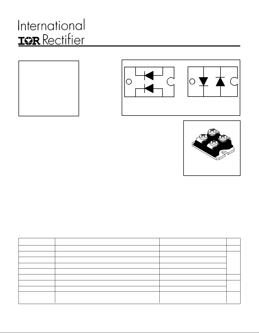
HFA120FA60, HFA120EA60
TM
Ultrafast, Soft Recovery DiodeHEXFRED
VR = 600V
K2
A2
VF(typ.)* = 1.4V
I
= 60A
F(AV)
Qrr (typ.) = 270nC
I
(typ.) = 7.0A
RRM
trr(typ.) = 65ns
di
/dt (typ.)* = 270A/µs
(rec)M
K1
HFA120FA60
A1
Features
• Fast Recovery time characteristic
• Eletrically isolated base plate
• Large creepage distance between terminal
• Simplified mechanical designs, rapid assembly
Description
This SOT-227 modules with FRED rectifier are available in two basic
configurations. They are the antiparallel and the parallel configurations.
The antiparallel configuration (HFA120EA60) is used for simple series
rectifier and high voltage application. The parallel configuration
(HFA120FA60) is used for simple parallel rectifier and high current application.
The semiconductor in the SOT-227 package is isolated from the copper
base plate, allowing for common heatsinks and compact assemblies to be
built.
These modules are intended for general applications such as power
supplies, battery chargers, electronic welders, motor control, DC chopper,
and inverters.
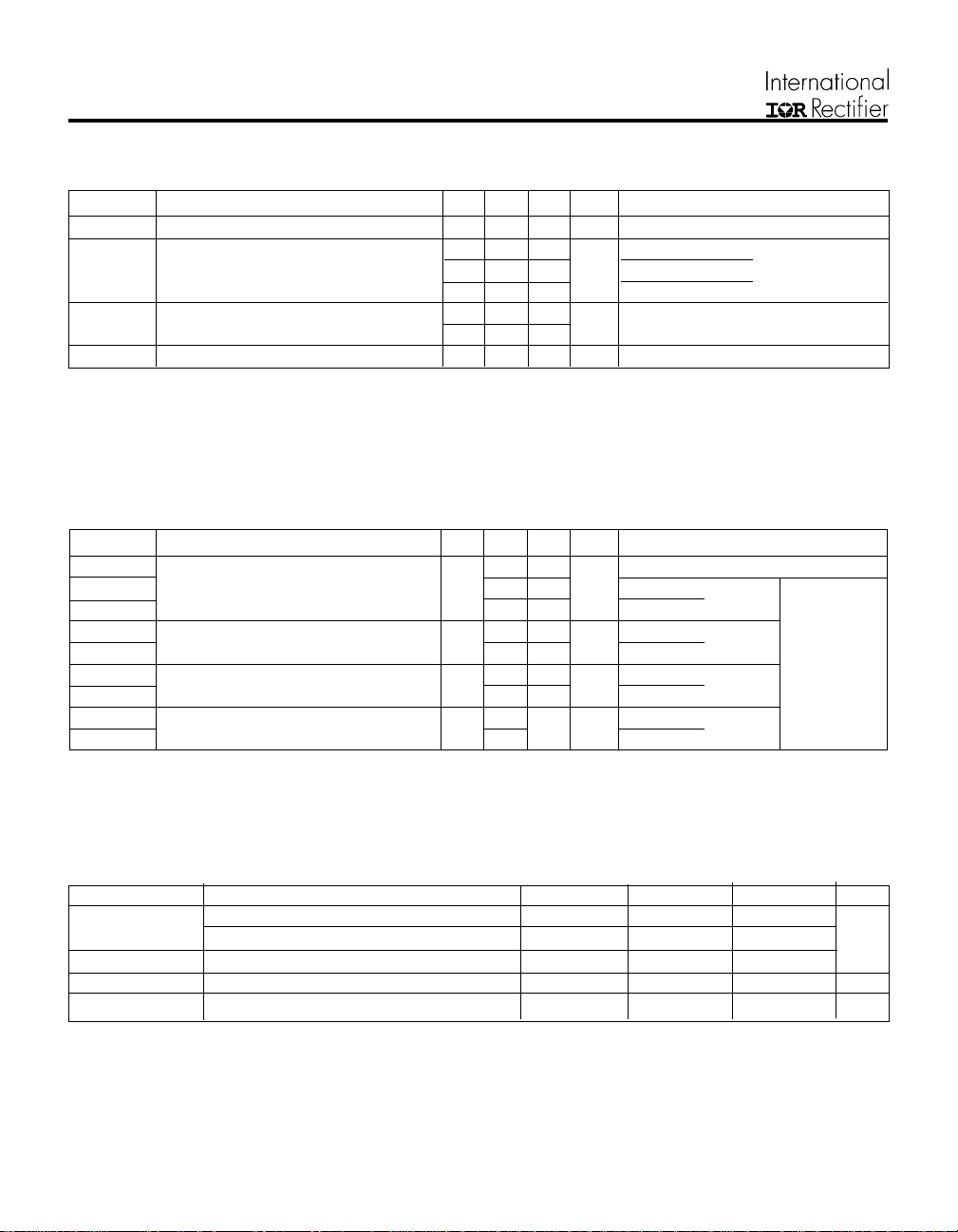
Absolute Maximum Ratings (per Leg)
Parameter Max. Units
V
R
@ TC = 25°C Continuous Forward Current 75
I
F
@ TC = 100°C Continuous Forward Current 40
I
F
I
FSM
I
FRM
V
ISOL
@ TC = 25°C Maximum Power Dissipation 180
P
D
PD @ TC = 100°C Maximum Power Dissipation 71
T
J
T
STG
*125 °C
Cathode-to-Anode Voltage 600 V
Single Pulse Forward Current TBD
Maximum Repetitive Forward Current 180
RMS Isolation Voltage, Any Terminal to Case, t=1 min 2500 V
Operating Junction and
Storage Temperature Range
-55 to +150
A2
K2
K1
A1
HFA120EA60
SOT-227
A
W
°C
10/09/97
HFA120FA60, HFA120EA60
Electrical Characteristics (per Leg) @ TJ = 25°C (unless otherwise specified)
Parameter Min. Typ. Max. Units Test Conditions
V
BR
V
FM
I
RM
C
T
Dynamic Recovery Characteristics (per Leg) @ TJ = 25°C (unless otherwise specified)
t
rr
t
rr1
t
rr2
I
RRM1
I
RRM2
Q
rr1
Q
rr2
di
(rec)M
di
(rec)M
Cathode Anode Breakdown Voltage 600 ––– ––– V IR = 100µA
Max Forward Voltage
Max Reverse Leakage Current
––– 1.5 1.7 I
––– 1.9 2.1 V IF = 120A
––– 1.4 1.6 I
––– 2.5 20 V
––– 130 2000 TJ = 125°C, VR = 0.8 x VR Rated
= 60A
F
= 60A, TJ = 125°C
F
R
µA
= VR Rated
Junction Capacitance ––– 120 170 pF VR = 200V
Parameter Min. Typ. Max. Units Test Conditions
Reverse Recovery Time ––– 3 4 ––– IF = 1.0A, dif/dt = 200A/µs, VR = 30V
See Fig. 5, 6 & 16
––– 65 98 ns TJ = 25°C
––– 130 200 TJ = 125°C IF = 60A
Peak Recovery Current ––– 7.0 13 TJ = 25°C
See Fig. 7& 8
––– 13 23 TJ = 125°C VR = 200V
Reverse Recovery Charge ––– 270 410 TJ = 25°C
See Fig. 9 & 10
––– 490 740 TJ = 125°C dif/dt = 200A/µs
/dt1 Peak Rate of Fall of Recovery Current – –– 350 ––– TJ = 25°C
/dt2 During t
b
See Fig. 11 & 12
––– 270 ––– TJ = 125°C
A
nC
A/µs
See Fig. 1
See Fig. 2
D Rated
See Fig. 3
Thermal - Mechanical Characteristics
Parameter Min. Typ. Max. Units
R
θJC
R
θCS
Wt Weight –––– 30 –––– gm
Junction-to-Case, Single Leg Conducting –––– –––– 0.70
Junction-to-Case, Both Legs Conducting –––– –––– 0.35
Case-to-Sink, Flat , Greased Surface –––– 0.05 ––––
°C/W
K/W
Mounting Torque –––– 1.3 –––– (N•m)

HFA120FA60, HFA120EA60
1000
(A)
F
100
T = 150°C
J
T = 125°C
J
T = 25°C
J
10
Instantaneous Forward Current - I
1
0.0 0.5 1.0 1.5 2.0 2.5 3.0
Forward Voltage Drop - V (V)
FM
Fig. 1 - Maximum Forward Voltage Drop
vs. Instantaneous Forward Current,
(per Leg)
1
10000
1000
(µA)
R
100
10
Reverse Current - I
1
0.1
T = 150°C
J
T = 125°C
J
T = 25°C
J
0 200 400 600
Reverse Voltage - VR ( V )
Reverse Voltage - V (V)
R
Fig. 2 - Typical Reverse Current vs. Reverse
A
10000
(pF)
T
1000
100
Junction Capacitance -C
10
1 10 100 1000
Voltage, (per Leg)
T = 25°C
J
Reverse Voltage - V (V)
R
Fig. 3 - Typical Junction Capacitance vs.
Reverse Voltage, (per Leg)
D = 0.50
thJC
0.20
0.1
0.10
P
1 2
DM
t
1
t
2
0.05
0.02
0.01
Thermal Response (Z )
0.01
0.00001 0.0001 0.001 0.01 0.1 1
Fig. 4 - Maximum Thermal Impedance Z
SINGLE PULSE
(THERMAL RESPONSE)
t , Rectangular Pulse Duration (sec)
1
Characteristics, (per Leg)
thjc
Notes:
1. Duty factor D = t / t
2. Peak T = P x Z + T
J DM thJC C

HFA120FA60, HFA120EA60
200
V = 200V
R
T = 125°C
J
T = 25°C
J
I = 12 0 A
160
120
trr- (ns)
80
40
100 1000
di /dt - (A/µs)
f
F
I = 60 A
F
I = 30 A
F
Fig. 5 - Typical Reverse Recovery vs. dif/dt,
(per Leg)
4000
V = 20 0V
R
T = 125°C
J
T = 25°C
J
100
V = 200V
R
T = 125°C
J
T = 25° C
J
I = 120A
F
I = 60 A
F
I = 30A
F
10
Irr- ( A)
1
100 1000
di /dt - (A/µs )
f
Fig. 6 - Typical Recovery Current vs. dif/dt,
(per Leg)
10000
V = 200 V
R
T = 125°C
J
T = 25°C
J
3000
2000
I = 120A
F
I = 60 A
F
I = 30 A
F
Qrr- (nC)
1000
0
100 1000
di /dt - (A/µs )
f
Fig. 7 - Typical Stored Charge vs. dif/dt,
(per Leg)
I = 120A
F
I = 60 A
F
I = 30A
1000
F
di (rec) M/dt- (A /µs)
100
100 1000
Fig. 8 - Typical di
di /dt - (A/µs )
f
/dt vs. dif/dt,
(rec)M
(per Leg)

REVERSE RECOVERY CIRCUIT
V = 200V
R
Ω
0.01
L = 70µH
D.U.T.
dif/dt
A DJU ST
G
D
IR FP250
S
HFA120FA60, HFA120EA60
3
t
RRM
rr
I
RRM
t
b
0.5
t
a
2
di(rec)M/dt
0.75 I
RRM
4. Qrr - Area under curve defined by t
and I
RRM
t
Qrr =
2
5. di
/dt - Peak rate of change of
(rec)M
current during t
4
Q
rr
I
RRM
X I
rr
portion of t
b
5
rr
RRM
rr
I
F
0
1
di /dt
f
1. dif/dt - Rate of change of current
through zero crossing
2. I
- Peak reverse recovery current
RRM
3. trr - Reverse recovery time measured
from zero crossing point of negative
going I
to point where a line passing
F
through 0.75 I
extrapolated to zero current
and 0.50 I
RRM
Fig. 9 - Reverse Recovery Parameter Test
Circuit
L = 100µ H
DUT
Rg = 25 ohm
FREE -W HEEL
DIODE
CURRE NT
MONITOR
Fig. 11 - Avalanche Test Circuit and Waveforms
HIGH -SPEED
SW ITCH
Vd = 50V
Fig. 10 - Reverse Recovery Waveform and
Definitions
I
L(PK)
+
DE C A Y
TIME
V
(AVAL)
V
R(RA TE D)

HFA120FA60, HFA120EA60
SOT-227 Package Details
Tube
LEAD ASSIGNMENTS
QUANTITIES PER TUBE IS 10
M4 SREW AND WASHER INCLUDED
WORLD HEADQUARTERS: 233 Kansas St., El Segundo, California 90245, Tel: (310) 322 3331
EUROPEAN HEADQUARTERS: Hurst Green, Oxted, Surrey RH8 9BB, UK Tel: ++ 44 1883 732020
IR CANADA: 7321 Victoria Park Ave., Suite 201, Markham, Ontario L3R 2Z8, Tel: (905) 475 1897
IR FAR EAST: K&H Bldg., 2F, 30-4 Nishi-Ikebukuro 3-Chome, Toshima-Ku, Tokyo Japan 171 Tel: 81 3 3983 0086
IR SOUTHEAST ASIA: 315 Outram Road, #10-02 Tan Boon Liat Building, Singapore 0316 Tel: 65 221 8371
http://www.irf.com/ Data and specifications subject to change without notice. 10/97
IR GERMANY: Saalburgstrasse 157, 61350 Bad Homburg Tel: ++ 49 6172 96590
IR ITALY: Via Liguria 49, 10071 Borgaro, Torino Tel: ++ 39 11 451 0111
 Loading...