

Page 1
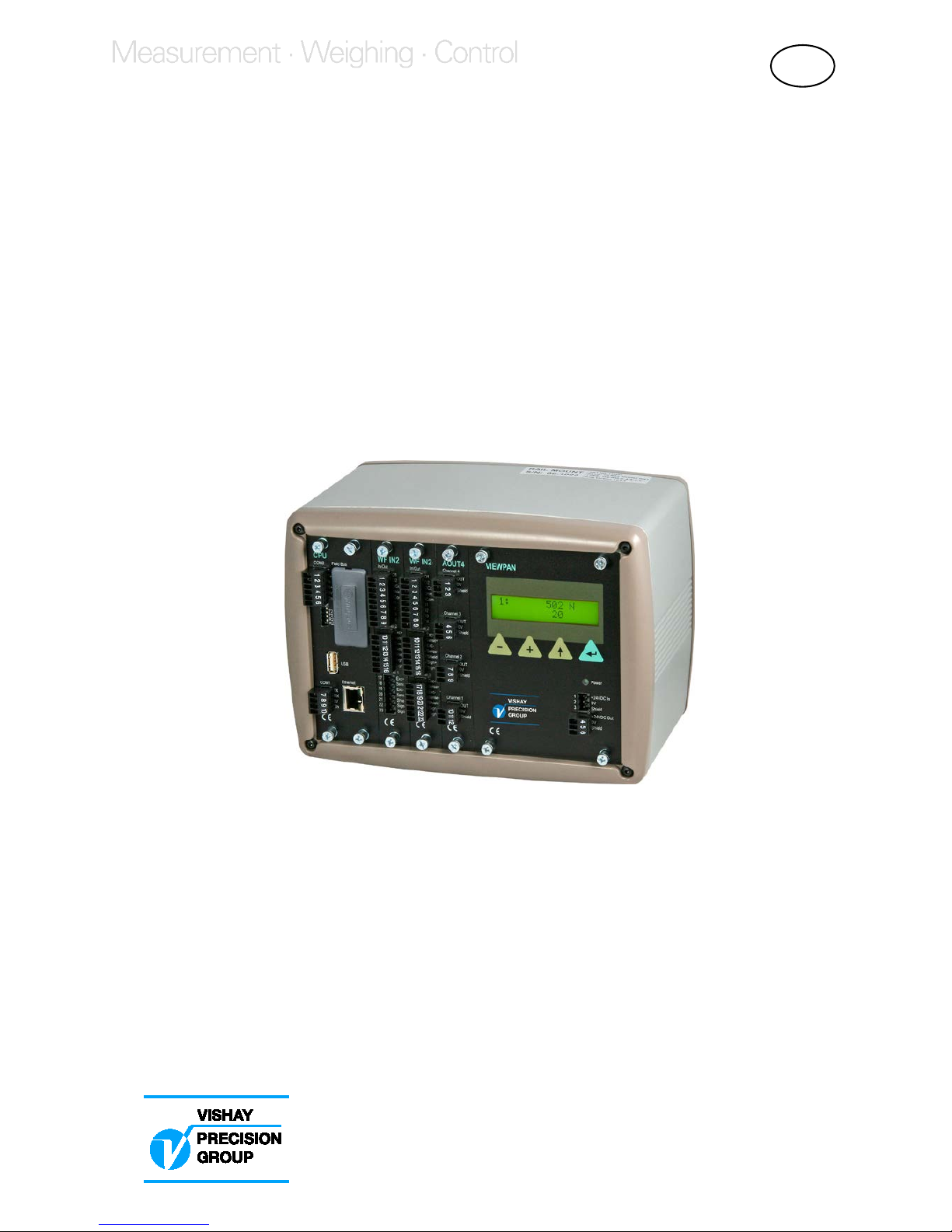
G4 Multi Channel
Force Instrument
Program version 101.1.0.0
Technical Manual
RM type
GB
Page 2

Page 3

G4 Multi Channel Force Instrument
1. Introduction
Manual updates ..................................... 1-1
General .................................................. 1-1
Functions ............................................... 1-2
Maintenance .......................................... 1-4
Safety information .................................. 1-4
Technical data ....................................... 1-5
Ordering information .............................. 1-12
2. Installation
Mechanical installation ........................... 2-1
Electrical installation .............................. 2-2
CPU unit ................................................. 2-3
VIEWPAN module ................................. 2-5
WF IN, WF IN2 and HS WF2 ................. 2-6
AOUT1 and AOUT4 ............................... 2-9
DIO8 ...................................................... 2-10
Profibus-DP Fieldbus Adaptor ................ 2-11
DeviceNet Fieldbus Adaptor .................. 2-13
3. Instrument Functionality
General ................................................... 3-1
Function Block ........................................ 3-1
4. Set-up
General .................................................. 4-1
Operators interface ................................ 4-2
Menu structure ....................................... 4-6
Parameters ............................................ 4-8
5. Calibration
General .................................................. 5-1
Common parameters ............................. 5-2
Calibration using datasheet ................... 5-3
Using parameters values from
a previous calibration ............................. 5-4
Calibration with known forces ................. 5-5
6. Operation
General .................................................. 6-1
Power supply ......................................... 6-1
Power-up sequence ............................... 6-1
Operating display ................................... 6-2
Security locks ........................................ 6-3
Zero setting ............................................ 6-3
Main menu ............................................. 6-4
Level supervision ................................... 6-5
Use of inputs and outputs ...................... 6-6
Filter function ......................................... 6-7
7. Communication
General .................................................. 7-1
Serial interface ........................................ 7-1
Modbus RTU Slave ................................ 7-1
Modbus TCP Slave ................................ 7-2
Modbus protocol .................................... 7-3
Fieldbus interface .................................... 7-28
8. Remote Access
General .................................................. 8-1
Browser requirements ............................. 8-1
Using the Remote Access ...................... 8-2
Security ................................................... 8-2
Remote Access Login and Logout .......... 8-3
Remote / Local Access ........................... 8-6
Remote Set-up ........................................ 8-7
Remote Access Maintenance ................. 8-10
9. Maintenance
General .................................................. 9-1
Diagnostics ............................................. 9-1
File handling ........................................... 9-4
Create Backup ....................................... 9-5
Restore Backup ..................................... 9-5
Set Default .............................................. 9-5
Program Upgrade ................................... 9-5
Instrument Restart .................................. 9-6
10. Troubleshooting
General ................................................... 10-1
Error codes ............................................ 10-1
Appendix
Declaration of Conformity ........................ App.1
Contents
Page 4

Technical Manual
PRECAUTIONS
READ this manual BEFORE operating or servicing this instrument.
FOLLOW these instructions carefully.
SAVE this manual for future reference.
DO NOT allow untrained personnel to operate,
clean, inspect, maintain, service, or tamper with
this instrument.
WARNING
Only permit qualified personnel to install and service this instrument.
Exercise care when making checks, tests and adjustments
that must be made with power on.
Failing to observe these precautions can result in bodily harm.
!
Page 5
G4 Multi Channel Force Instrument
1-1
1. Introduction
Manual updates
This manual is updated for the 101.1.0.0 program version. In this program is a web
server added which enables for the user to access the instrument using a PC running a
web browser. This manual can also be used for the previous program version
(101.0.0.0) where the only differences are the ‘Network Config.’ menu, the Instrument
restart functionality and the remote access part.
General
The G4 Instrument is a high performance multi channel force indicator intended for
industrial systems.
Its basic function is to convert the signals from strain gauge transducers to useful force
information. Transducer excitation is included as well as parameter controlled signal
processing, indication of output levels, error supervision and operation of optional
external equipment. The instrument can be equipped with up to 6 synchronized force
channels.
The instrument is modular and can be equipped with different types of I/O units to
match the demands in the specific applications. There are strain gauge transducer
interface modules, a digital input/output module, analog output modules.
Internal solid-state outputs in the instrument can be used for output functions from level
supervision or ‘In process’ indication, reporting the operating status of the G4
Instrument.
The CPU unit in the instrument has several communication interfaces. It has two serial
communication ports, an Ethernet port, an USB port and a fieldbus slot.
Several G4 Instruments can be controlled from a master computer or PLC.
Serial communication interfaces are RS-485 and RS-232 using Modbus RTU protocol.
The Ethernet interface is using Modbus TCP and the optional fieldbus interface uses
Profibus or DeviceNet.
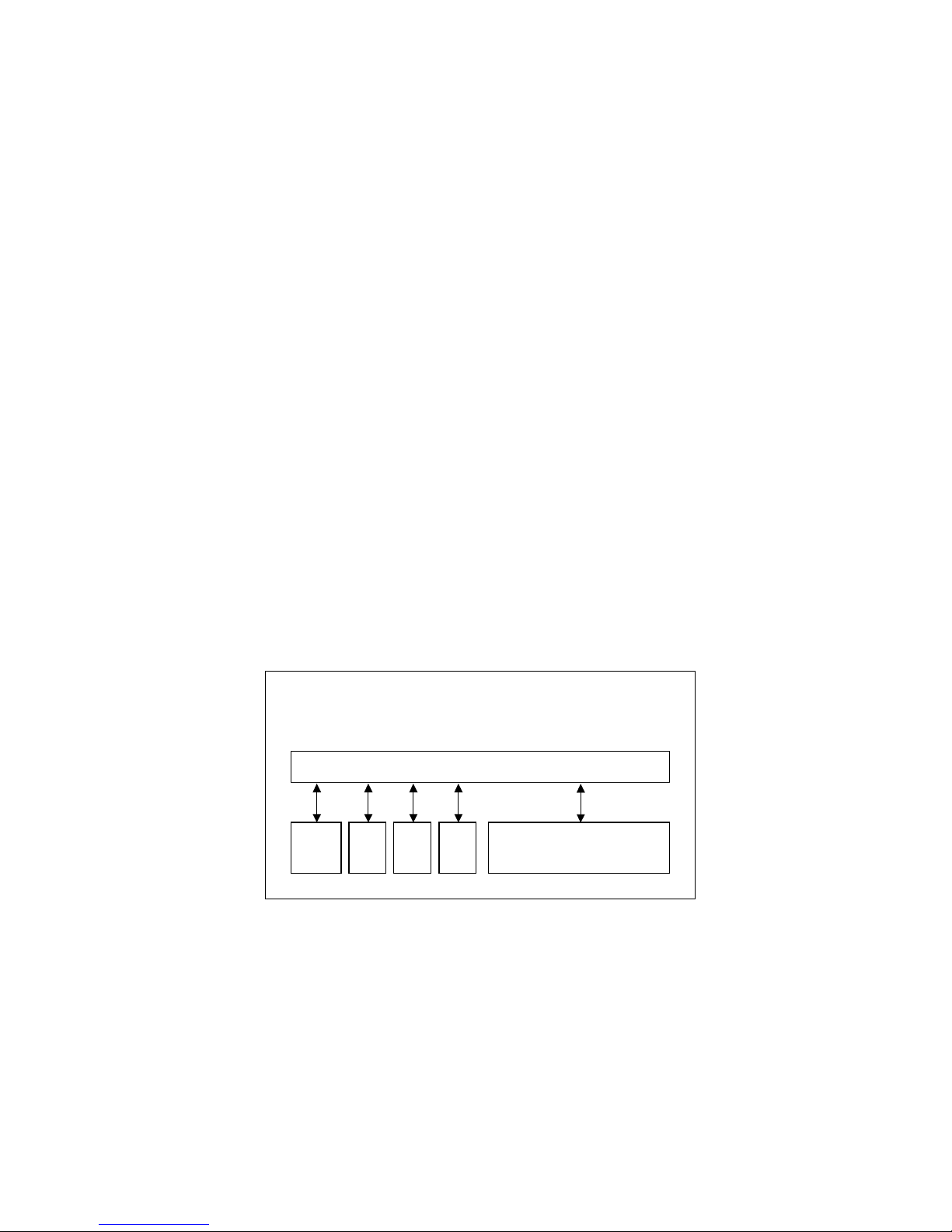
CPU
unit
I/O
unit
1
I/O
unit
2
I/O
unit
3
Service panel with
Power supply unit
Backplane
DIN rail mount version
Enclosure & mounting accessories
Block structure of a G4 Instrument
Page 6

Technical Manual
1-2
It is possible to load new software into the instrument using the USB port.
All functions in the G4 Instrument are controlled by set-up parameters. Setting of
parameter values can be performed via a service panel with display and 4 keys
(VIEWPAN module).
The Rail mount instrument type is powered with 24 V DC. All input and output signals
are galvanically isolated from the power supply by operational insulation.
Functions
Measurement with strain gauge transducers.
Both excitation voltage and output signal are measured at the transducer to avoid
influence from voltage drop in the connection cable. Excitation to the transducer, from
the G4 Instrument is provided over separate wires.
A shielded 6-wire cable must be used to connect a distant transducer to the instrument.
A/D conversion.
The analog signals from the transducer are converted to digital form and filtered
to give an internal transducer signal with high resolution.
Calculation.
The transducer excitation and signal values are combined to form an internal
transducer signal, representing the load on the transducer. Influenced by calibration
data, this signal is converted to a digital measurement value, the force value, which
can be presented at the local display window and at external equipment.
Error supervision.
As long as the error supervision detects no error, the signal ‘In process’ is present
but if an error is detected, ‘In process’ will be off and a specific error message will be
displayed. ‘In process’ can be set to control any digital output. Note that there are
force channel specific and instrument specific error detection.
Levels.
32 level comparators in the instrument can be set to switch at defined signal levels with
any selected hysteresis added, meaning that the switch level can be different for
increasing and decreasing signal. It’s possible to set level switching delays. Output
signals from these comparators are available on the serial communication. The level
comparator outputs can also be set to control digital outputs from the instrument.
Communication.
The G4 Instrument utilizes the serial interface, Ethernet and a fieldbus interface for
communication with control computer. The serial interface consists of a RS-232
(COM1) connection and a RS-485/RS-422 (COM2) connection. COM2 can be used
with 2- or 4-wire connection.
Force values, web tension values, level status, error status etc. can be collected and
commands given through the communication interfaces. Modbus RTU protocol is used
for the serial interfaces and Modbus TCP for the Ethernet connection. For the optional
fieldbus interface Profibus or DeviceNet can be used.
Page 7

G4 Multi Channel Force Instrument
1-3
Instrument modes.
In normal operation mode the G4 Instrument is presenting the measurement values on
the front panel (VIEWPAN) alphanumerical display. Values for one Function Block at a
time can be shown. During parameter set-up the instrument will continue normal
operation. However if hardware set-up parameters have been changed the instrument
will be restarted.
The operator will always be notified before the instrument is restarted.
Parameter setting.
In the instrument all operating functions are controlled by set-up parameters with
numerical values, string values, or pre-selected values from a list of alternatives.
Parameter set-up is performed by the keys at the service panel (VIEWPAN).
Presentation.
The instrument can present measured or calculated values, parameter settings etc.
at the front panel. An extensive system of menus gives the possibility to present
various information about the instrument. The VIEWPAN module can present one or
two values at a time.
Measured or calculated values, status of levels and so on, can be transferred to
external equipment via the different communication interfaces (some are optional).
Page 8

Technical Manual
1-4
Maintenance
The G4 instrument needs no maintenance, performed by the end-user. Any service
or repair work must be performed by qualified personnel.
Contact your supplier.
Cleaning
Before cleaning the G4, break the power connection to the instrument.
Use a soft cloth to clean the exterior of the instrument.
Safety information
Utilization.
Before connecting power to the instrument, check that all fixation screws
at the modules are tightened so that the instruments functional grounding
by the housing is maintained.
The instrument may only be utilized for the measurement and control functions,
described in this Technical Manual. It is especially important to adhere to the load limits
of the input/output connectors. We accept no responsibility for any damage arising from
improper operation.
Any changes to the instrument, which causes any function changes, may only be
carried out by the manufacturer, or after discussion with and permission by the
manufacturer.
Meaning of symbols, used in this manual
Direct current.
!
Caution, risk of danger. Documentation needs to be consulted.
Page 9
G4 Multi Channel Force Instrument
1-5
Technical data
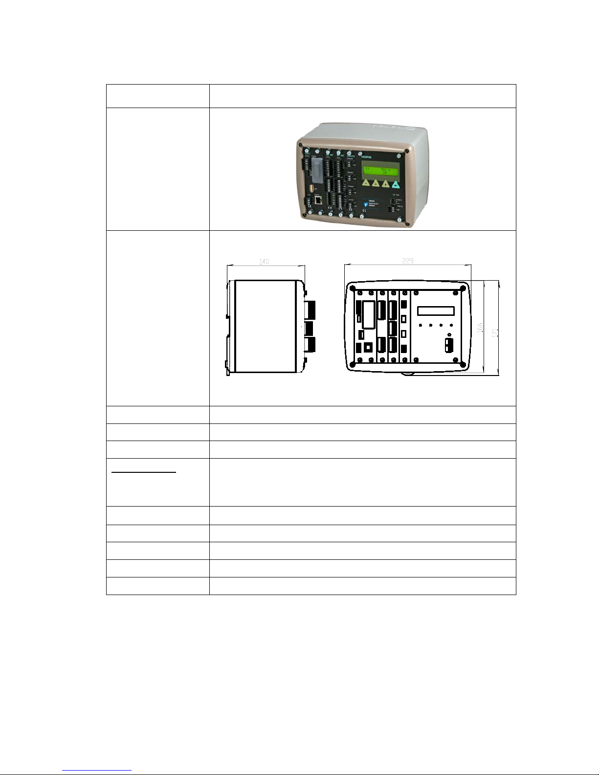
Enclosure type RM – Rail Mount enclosure
Dimensions
Enclosure design Aluminium housing with plastic frames
Rail mount DIN 46 277/3 and DIN EN 50022 (w=35 mm, h=7.5 mm)
Display, keyboard See VIEWPAN module
Environmental
Temperature range
Rated performance: -10 to +50 °C
Storage: -25 to +85 °C
Relative humidity
Max. 85% up to 40 °C, decreasing linear to 50% at 50 °C
Rated pollution Pollution degree 2
Protection IP20. For indoor use.
Altitude Up to 2000 m
EMC, RF CE (Industrial), OIML
Page 10
Technical Manual
1-6
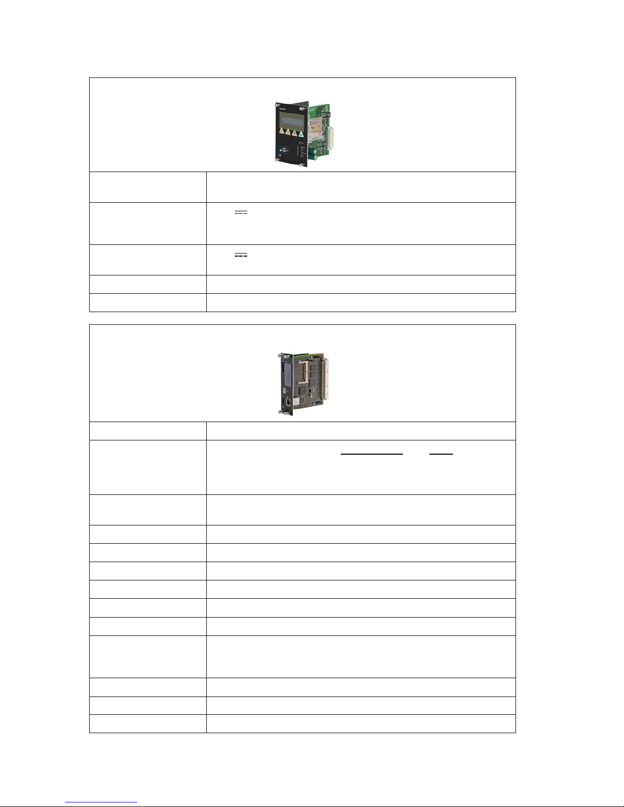
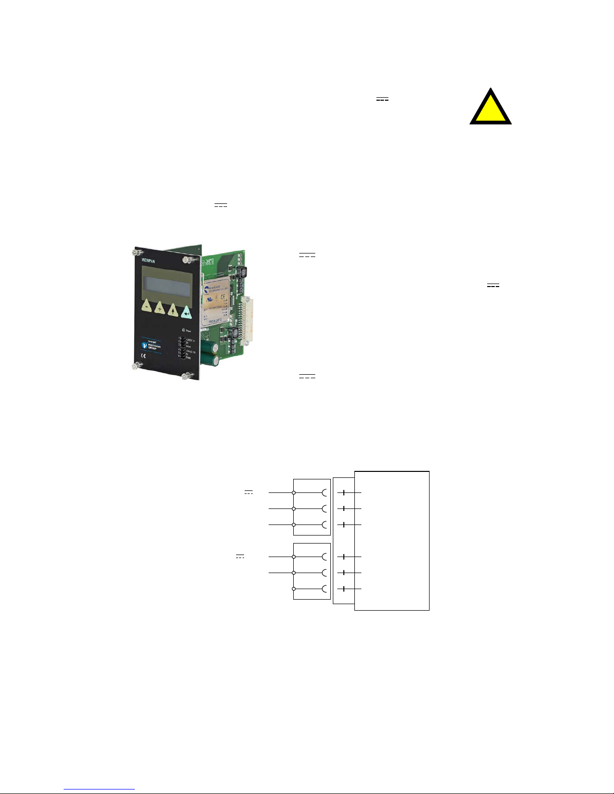
VIEWPAN
Module type Display/keypad interface with integrated power supply for the
complete instrument.
Input voltage 24 V ±15% including fluctuations, 40W
Impulse withstand (overvoltage)
category I of IEC 60364-4-443
Output voltage 24 V output 0.1 A
The same voltage as input voltage
Display
2 x 16 character LCD with backlight
Keyboard 4 keys
CPU
Module type CPU module
RTC backup battery
Manufacturer Type
Lithium battery Panasonic-BSG CR2032
CR2032 3V GP Batteries CR2032
Varta CR2032 (V)
COM1 (RS232) and
COM2 (RS485)
For process data and control
Isolated by operational insulation
Protocol Modbus RTU
Baud rate Up to 115 kbaud
Fieldbus
For process data and control (optional)
Types Profibus or DeviceNet
USB
Version 1
Keyboard USB keyboard for PC
USB Memory USB type for PC
For backup and restore of set-up parameters
For change to a new program version
Ethernet
10/100BASE-T. For process data and control
Protocols Modbus TCP, ftp, http
RJ45 Indications Green LED: Transmitting. Yellow LED: Receiving.
Page 11
G4 Multi Channel Force Instrument
1-7
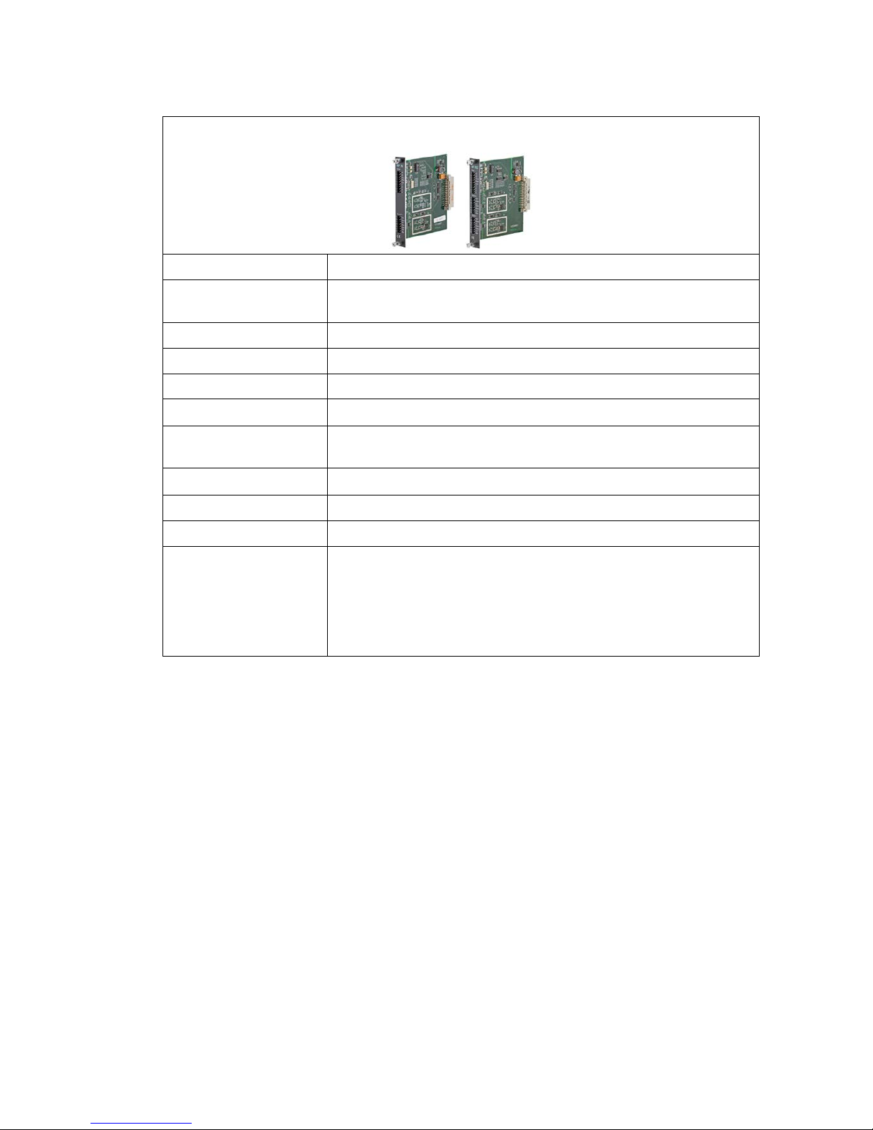
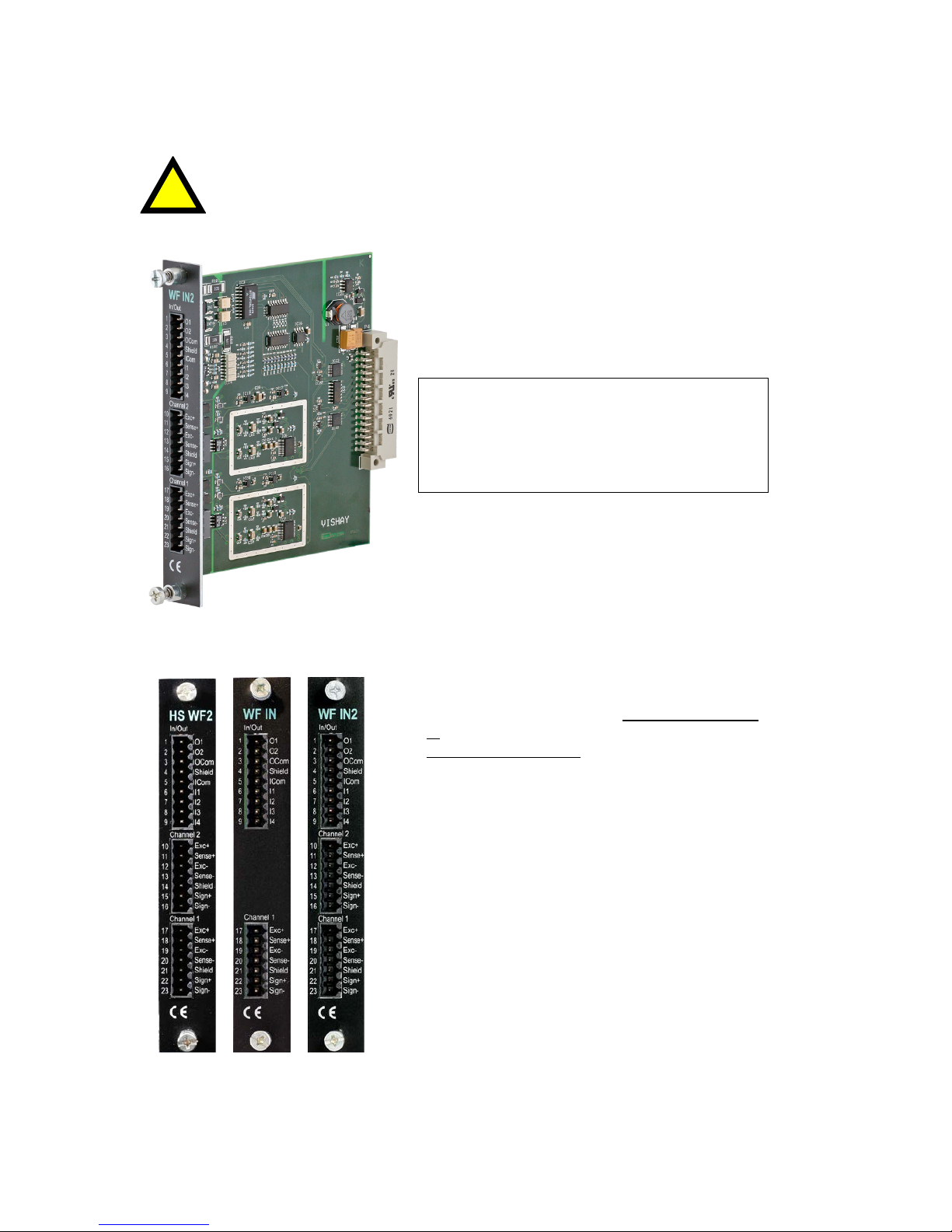
WF IN / WF IN2
Module type Weight/Force input module
Max. # of transducers 8 (350 ohm) per channel
Maximum 48 transducers per instrument
Excitation voltage: 5 VDC
A/D conversion: 3.9 kHz, 16 000000 units (24 bits)
Input range +/- 7 mV/V
Update rate:
9.3 − 300 readings per second
No. of channels: WF IN has 1 Weight/Force channel
WF IN2 has 2 Weight/Force channels
Sensitivity:
0.1 µV
Zero drift: <10 nV/V/K
Span drift: <2 ppm/K
Digital I/O 4 inputs, 24 V ±15%, 5 mA from external power supply,
isolated by operational insulation
and with common return
2 outputs, 24 V ±15%, max 100 mA from external power supply,
isolated by operational insulation
and with common return
Page 12

Technical Manual
1-8
HS WF2
Module type High Speed Weight/Force input module
Max. # of transducers 4 (350 ohm) per channel
Excitation voltage: 10 VDC
A/D conversion: 20 kHz, 16 000000 units (24 bits)
Input range +/- 4.5 mV/V
Update rate:
25 − 800 readings per second
No. of channels: HS WF2 has 2 Weight/Force channels,
separately isolated by operational insulation
Sensitivity:
0.1 µV
Zero drift: <10 nV/V/K
Span drift: <2 ppm/K
Digital I/O 4 inputs, 24 V ±15%, 5 mA from external power supply,
isolated by operational insulation
and with common return
2 outputs, 24 V ±15%, max 100 mA from external power supply,
isolated by operational insulation
and with common return
Page 13
G4 Multi Channel Force Instrument
1-9
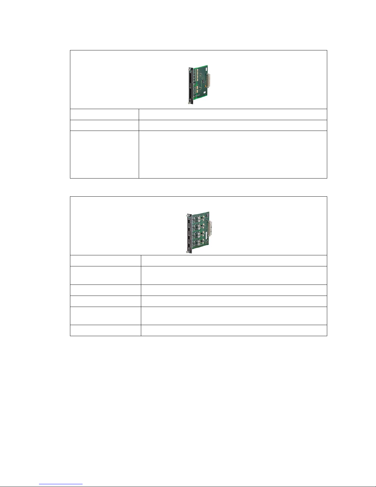
DIO8
Module type Digital input/output module
Separate I/O module 2 units can be used
Digital I/O 8 inputs, 24 V ±15%, 5 mA from external power supply,
isolated by operational insulation
and with common return
8 outputs, 24 V ±15%, max 100 mA from external power supply,
isolated by operational insulation
and with common return
AOUT1 / AOUT4
Module type Analog output module
Number of channels 1 or 4 channels,
separately isolated by operational insulation
Resolution 65000 units, 16 bits
Voltage output 0 – 10 V, -10 – 10 V, > 1 kohm load
Current output 4 – 20 mA, 0 – 20 mA, -12 – 20 mA, -20 – 20 mA,
< 500 ohm load
Update rate Function Block update rate, adjustable smoothing filter
Page 14

Technical Manual
1-10
Profibus-DP
Module type Profibus-DP fieldbus adaptor
Connector Profibus 9-pin, female D-sub (DB9F)
Baudrate Auto setting 9.6 kbps – 12 Mbps
Address 1 – 125, set by parameter
Fieldbus data 16 bytes from fieldbus to instrument.
32 – 244 bytes from instrument to fieldbus (may be limited by
the master).
See chapter ‘7 Communication’ section
‘Fieldbus communication interface’ for details on fieldbus data
mapping.
Mounting The fieldbus adaptor is mounted through the front of
the CPU module with LED’s and connector accessible through
the CPU front panel.
Remove the plastic cover from the fieldbus slot in the CPU
module front panel. Insert the adaptor very carefully and make
absolutely sure that the adaptor slides correctly into the guides
in the connector on the CPU PCB. Tighten
the two fastening screws at the adaptor front and check
that the two securing hooks locks into the CPU PCB.
Settings All fieldbus settings are done with setup parameters in
the instrument. No settings are done on the module itself.
Page 15
G4 Multi Channel Force Instrument
1-11
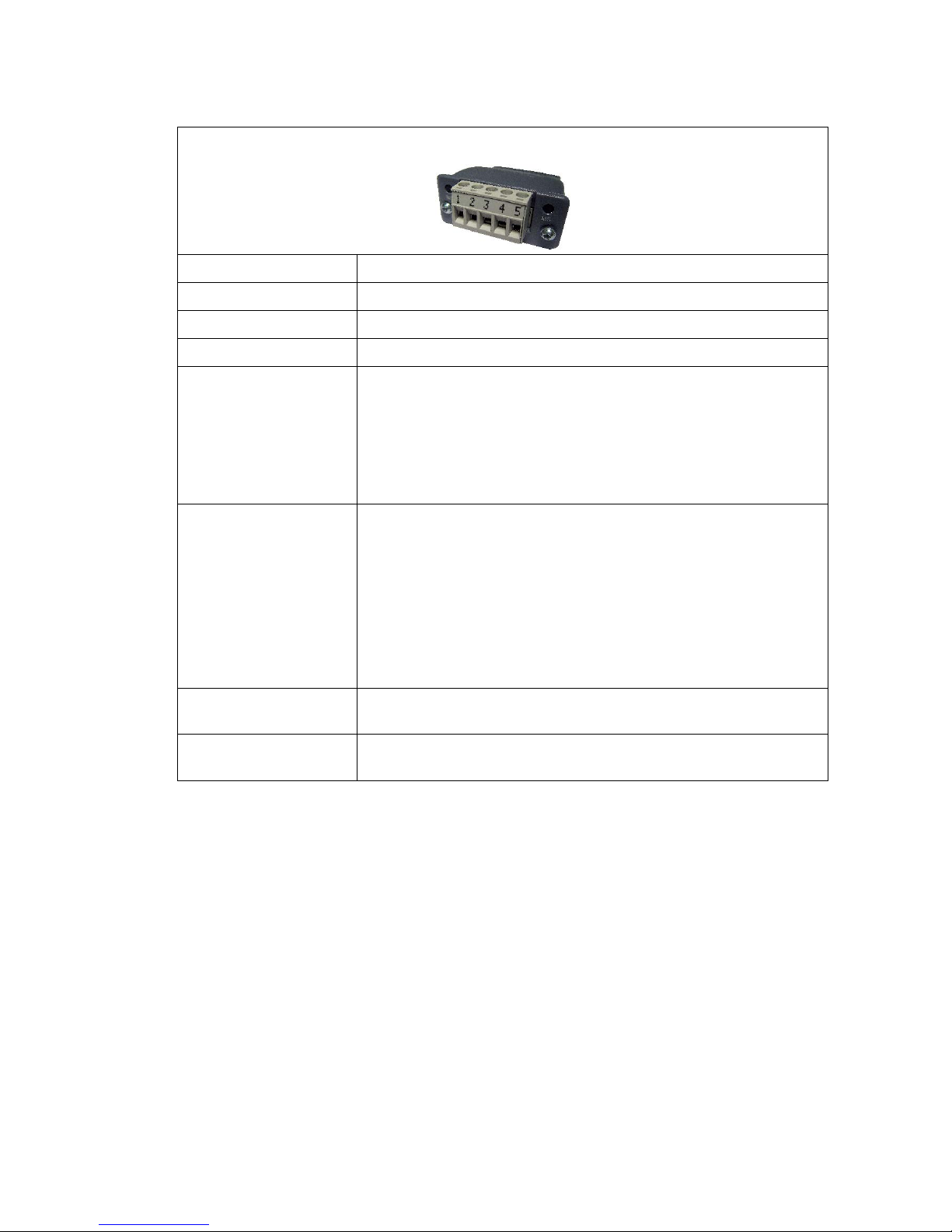
DeviceNet
Module type DeviceNet fieldbus adaptor
Connector 5 pin male connector.
Baudrate 125, 250, 500 kbps or Auto. Set by parameter.
Address 0 – 63, set by parameter
Fieldbus data 16 bytes from fieldbus to instrument.
32 – 244 bytes from instrument to fieldbus (may be limited by
the master).
See chapter ‘7 Communication’ section
‘Fieldbus communication interface’ for details on fieldbus data
mapping.
Mounting The fieldbus adaptor is mounted through the front of
the CPU module with LED’s and connector accessible through
the CPU front panel.
Remove the plastic cover from the fieldbus slot in the CPU
module front panel. Insert the adaptor very carefully and make
absolutely sure that the adaptor slides correctly into the guides
in the connector on the CPU PCB. Tighten
the two fastening screws at the adaptor front and check
that the two securing hooks locks into the CPU PCB.
Settings All fieldbus settings are done with setup parameters in
the instrument. No settings are done on the module itself.
Bus Supply Voltage According to the DeviceNet (Node) Specification:
nominal 24 VDC, range 11 – 25 VDC.
Page 16

Technical Manual
1-12
Ordering information
For Rail mount (RM) instruments
G4-RM-FB-S1-S2-S3-V-SW
G4 Instrument type G4
RM Enclosure type RM Rail mount
FB Fieldbus interface 0
P
D
None
Profibus
DeviceNet
Si Slot 1 to 3 type 0
2
3
4
6
7
8
Blank
HS WF2 High speed weight/force input module, 2 ch.
WF IN Weight/force input module, 1 channel.
WF IN2 Weight/force input module, 2 channels.
AOUT1 Analog Output module, 1 channel
AOUT4 Analog Output module, 4 channels
DIO8 Digital Input and output module
V User interface and
power
V VIEWPAN, 24VDC
SW Software (note 1)
W
F
S
(No code specified) Standard Weighing Program
Standard Weighing Program
Standard Force Program
Special Program (note 2)
Example: G4-RM-0-4-8-0-V-F
• G4 instrument (G4)
• Rail mount (RM)
• No field bus (0)
• Slot 1 = WF IN2 (4)
• Slot 2 = DIO8 (8)
• Slot 3 = Blank (0)
• Power =VIEWPAN unit (V)
• Software = Force program (F)
Note 1: The Software (SW) code specifies the program function that should be installed
in the instrument. If no code is specified the standard Weighing program will be
supplied.
Note 2: If a special program option is desired, the number of the special program must
be specified when ordering.
Page 17

G4 Multi Channel Force Instrument
1-13
Separate modules
Spec.no
Module type Module name
110 544 CPU CPU unit
110 546 HS WF2 High speed dual Weight/Force input module
110 547 WF IN Single Weight/Force input module
110 548 WF IN2 Dual Weight/Force input module
110 549 AOUT1 Single channel analog output module
110 550 AOUT4 Four channel analog output module
110 551 DIO8 Digital input/output module
110 552 BLANK Blank panel
110 554 VIEWPAN Rail mount service panel
110 559 PROFIBUS-DP Profibus DP fieldbus adaptor
110 560 DEVICENET DeviceNet fieldbus adaptor
Module selection rules
Every system needs 1 VIEWPAN module and 1 CPU module (can be equipped with
one fieldbus adaptor).
Limitations on number of I/O modules that can be used in one instrument:
• Maximum 3 modules (not counting the VIEWPAN module).
• Maximum 3 WF IN / WF IN2 or 2 HS WF2 modules.
• HS WF2 and WF IN(2) cannot be mixed in the same system
• Maximum 1 AOUT1 or 1 AOUT4 module.
• Maximum 2 DIO8 modules.
Page 18

Technical Manual
1-14
Page 19

G4 Multi Channel Force Instrument
2-1
2. Installation
Mechanical installation
See section ‘1. Introduction – Technical data’ for references to RM mechanical
measures.
G4, RM type, should be used in a dry, clean environment or it must be mounted
in a cabinet, protecting from water, dust etc. The instrument is prepared for
mounting on a flat surface by DIN rail according to Technical data.
The instrument needs minimum 200 mm space above this surface.
To remove the instrument from the rail, the black lever at the lower bottom side of
the instrument must be engaged.
Each instrument should have a free space of minimum 30 mm to the left
and to right, 100 mm above and below the instrument.
Cable ducts may be mounted in this free space.
All electrical connections to the instrument modules are made to terminals
at the front side so enough room for these terminals should be arranged.
CABLE DUCT
LOCK LEVER
TERMINALS
100
100
200
RM instrument.
Recommended free space at the instrument.
Page 20

Technical Manual
2-2
Electrical installation
The field wiring of the instrument shall be suitable to the environment
(e.g. chemically) in the end-user application.
Field wiring installation shall comply with any national regulations, hereunder National
Electrical Code (NEC) for US and/or Canadian Electrical Code for Canada.
• A switch or circuit-breaker shall be included in the building installation.
• The switch shall be in close proximity to the equipment and
within easy reach of the operator.
• The switch shall be marked as the disconnecting device for the equipment.
• The equipment switch or circuit-breaker employed as disconnecting device shall
comply with relevant requirements of IEC 60947-1 and IEC 60947-3.
For electrical installation with an external dc supply, see page 2-5.
WARNING
Make sure that that the power to the instrument is turned off before:
- any modules are removed from or inserted in the instrument.
- any connections are connected to or disconnected from the instrument.
All modules should be regarded as ESD sensitive. Make sure that an ESD safe
environment is maintained when inserting modules, removing modules and when
handling modules separately from the instrument. Modules must be kept in
metallised ESD bag when not mounted in the instrument.
!
Page 21
G4 Multi Channel Force Instrument
2-3
!
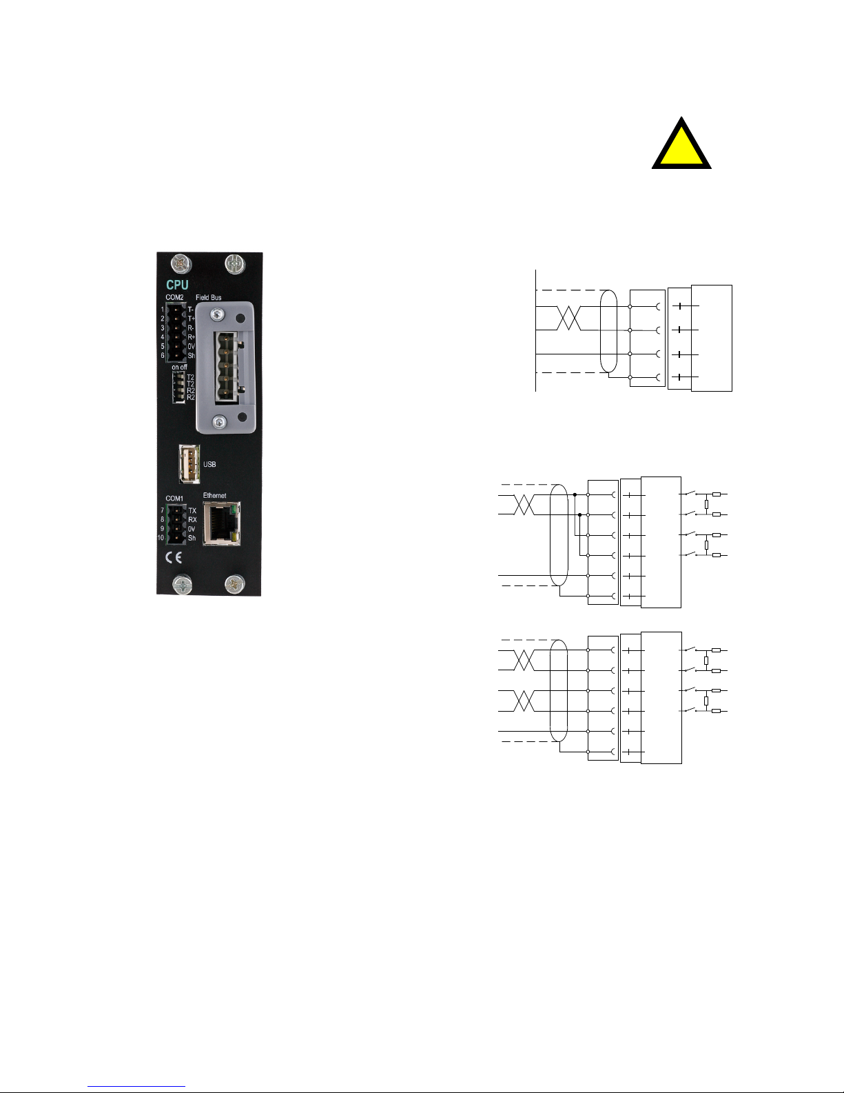
CPU unit
External computing devices connected to the CPU communication
interfaces of the instrument have to comply with the standard, UL 60950.
The internal battery in the CPU module is to be used only in the equipment
where servicing of the battery circuit and replacement of the lithium battery
will be done by a trained technician.
COM1
RS232 Serial communication.
This is a SELV/SELV-E circuit.
COM1 can be used for serial
communication with
computer/PLC (Modbus RTU).
Point to point communication,
only one G4 unit connected
to the computer/PLC.
Connections are made
to terminals 7 – 9.
Shielded cable must be used.
Connect shield to terminal 10.
COM2
RS485 Serial communication
for 2-wire or 4-wire with
common 0 V.
This is a SELV/SELV-E circuit.
COM2 can be used for serial
communication to
computer/PLC (Modbus RTU).
Connections are made
to terminals 1 – 5.
Shielded cable must be used.
Connect shield to terminal 6.
The communication lines must be terminated in
both ends. If G4 is connected at the end of the
communication line switches must be set as:
2-wire termination: Both T2 ON, both R2 OFF.
4-wire termination: Both T2 ON, both R2 ON.
TX
RX
0V
Shield
COM1 RS-232
10
9
8
7
(DTE)
RS-232
9p 25p
2 3
3 2
5 7
RS485 2-wire
1
TT+
RR+
0 V
Shield
COM2
6
2
3
4
5
+5
T2
T2
0
+5
R2
R2
0
RS485 4-wire
1
TT+
RR+
0 V
Shield
COM2
6
2
3
4
5
+5
R2
R2
0
+5
T2
T2
0
Page 22

Technical Manual
2-4
Field Bus
Slot for optional Fieldbus interface.
Profibus DP-V1 and DeviceNet are available.
See section Profibus-DP Fieldbus Adaptor or DeviceNet Fieldbus Adaptor later in this
chapter for details.
USB
Connector for USB device(s).
This port has no operational insulation and should be considered as a
SELV/SELV-E circuit.
Allows connection of following devices:
1 - USB Memory
2 - USB Keyboard
An USB hub can be used to allow connection of more than one device.
Ethernet
This is a SELV circuit. Uses crossover category 5 cable from RJ-45 Ethernet port
on the CPU front panel to PC (point to point connection) or standard cable to connect
to other equipment through a switch, hub or router which is isolating the circuit from the
public network.
Page 23
G4 Multi Channel Force Instrument
2-5
VIEWPAN module
The output of the external dc supply must be rated 24 V , ±15%
including fluctuations, min. 40 W. The supply must provide Double
Insulation between Mains parts and 24 V SELV or SELV-E Circuit, and a
limited-energy circuit (maximum available current of 8 A).
For the US market this energy limit can be achieved with an
ANSI/UL248-14 fuse rated 5A.
For other markets an IEC 60127 T type fuse rated 4A may also be used.
With integrated 24 V
power supply unit.
The integrated power supply is used to supply the complete instrument.
24 V input
Terminals 1, 2 and 3.
The G4 instrument should be powered by 24 V
,
connected according to the diagram below.
To achieve functional grounding, terminal 3
should be connected to ground.
See Technical data for input voltage ratings.
24 V output
Terminals 4 and 5 can be used to supply
max. 100 mA to digital inputs and outputs.
Connection should be according to
the diagram below.
See Technical data for ratings.
1
DC SUPPLY
2
0 V
3
Shield
4
5
0 V
6
Shield
0 V
Ground
0 V
+24 V In
+24 VDC In
+24 VDC Out+24 V Out
!
Page 24
Technical Manual
2-6
WF IN, WF IN2 and HS WF2
The voltage levels on connectors of I/O modules shall not exceed
hazardous voltage levels of 30 Vrms, 42.4 Vpeak or 60 Vdc under normal
conditions. In wet locations these voltage levels shall not exceed
16 Vrms, 22.6 Vpeak or 35 Vdc.
Transducer inputs
Terminals 17 – 23 (channel 1),
10 – 16 (channel 2).
Transducer connection should be handled with
great care to achieve good measuring data.
Transducer integrated cables may not be
shortened.
NOTE! Transducer cables must be routed at
least 200 mm away from 230/400 V, 50/60 Hz
power cables.
By cables with other frequencies or
high power, an even wider distance is
preferable.
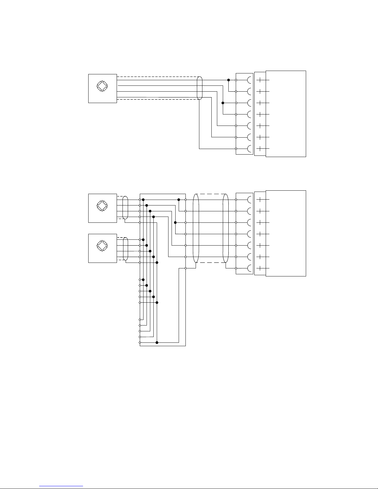
4-wire connection can be used if the transducer
integrated cable is long enough to be
connected directly to a transducer input. At
4-wire connection, some terminals must be
interconnected as shown in figure on next
page.
6-wire connection should be used if the
integrated cable must be lengthened or if
several transducers should be connected to
one transducer input.
The channel 1 cable shield must be connected
to terminal 21 and the channel 2 cable shield
must be connected to terminal 14.
In WF IN and WF IN2 the shield terminals are
internally connected to the G4 housing, which
is internally connected to earth via the power
supply connector pin 3 (shield). The shield
shall not be connected at any other point.
In HS WF2 the transducer input channels are
separately insulated by operational insulation
and the shields can be connected to the most
convenient ground/earth point. This can be the
junction box when using multiple transducers or
at the barrier ground when using Ex zener
barriers.
In the junction box SL-4 from Nobel Weighing
Systems, see figure, all necessary terminals
and interconnections are provided.
!
Page 25
G4 Multi Channel Force Instrument
2-7
10
15
13
12
11
14
16
Exc.-
Exc.+
Sign.+
Sign.-
4-wire connection
Transducer
Transducer input, ch. 2
Exc+
Sense+
ExcSenseSign+
SignShield
Junction box
17
22
20
19
18
21
23
Transducer input, ch. 1
Exc.-
Exc.+
Sign.+
Sign.-
Transducer
Transducer
Exc.-
Exc.+
Sign.+
Sign.-
6-wire connection
Exc+
Sense+
ExcSenseSign+
SignShield
A transducer may be connected directly to terminals at the transducer input.
For several transducers or long distance, a junction box
and lengthening cable is needed.
For a HS WF2 channel, the shield can be connected to
ground/earth at any point
Page 26
Technical Manual
2-8
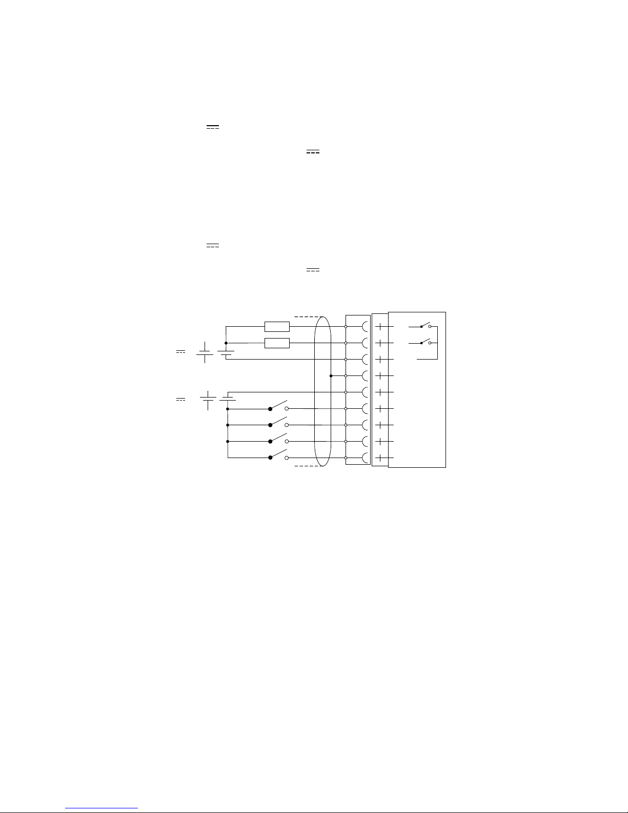
Digital inputs
Terminals 6 – 9 and terminal 5 (ICom) as a common connection.
Four digital inputs are provided, with functions that can be set in the G4 set-up.
External sourcing (24 V
) from the instrument power supply (max. 100 mA)
or from a separate DC supply must be used. Note that either the positive or
the negative pole of the voltage source (24 V
) can be connected to ICom (5).
Shielded cable/cables must be used, with the shield connected to terminal 4.
Solid state relay outputs
Terminals 1 and 2 with terminal 3 (OCom) as a common connection.
Two digital (relay) outputs are provided with contact rating given in Technical data.
External sourcing (24 V
) from the instrument power supply (max. 100 mA)
or from a separate DC supply should be used. Note that either the positive or
the negative pole of the voltage source (24 V
) can be connected to OCom (3).
Shielded cable/cables must be used, with the shield connected to terminal 4.
O1
O2
OCom
Shield
ICom
I1
I2
I3
I4
1
8
5
4
3
2
9
7
6
Load
Load
+
-
-
+
-
+
-
+
24 V
24 V
Page 27
G4 Multi Channel Force Instrument
2-9
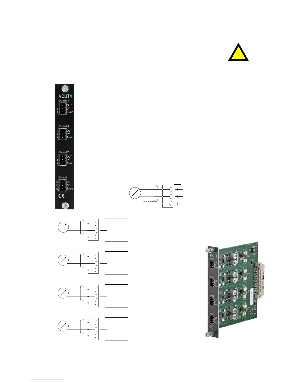
AOUT1 and AOUT4
The voltage levels on connectors of I/O modules shall not exceed
hazardous voltage levels of 30 Vrms, 42.4 Vpeak or 60 Vdc under normal
conditions. In wet locations these voltage levels shall not exceed 16 Vrms,
22.6 Vpeak or 35 Vdc.
Analog output unit
The AOUT4 unit has 4 analog output channels, independently
isolated by operational insulation.
The AOUT1 has 1 output channel, isolated by operational insulation.
The analog output signal will be connected to terminals
10, 11 (channel 1)
7, 8 (channel 2)
4, 5 (channel 3)
1, 2 (channel 4).
Shielded cable/cables must be used and the shield(s) must be connected
to the shield terminal(s) 12, 9, 6 and 3.
The shields can be connected to the most convenient ground/earth point.
OUT
0V
Shield
AOUT1 Channel 1
10
11
12
+
OUT
0V
Shield
Channel 1
10
11
12
OUT
0V
Shield
Channel 2
7
8
9
OUT
0V
Shield
Channel 3
4
5
6
OUT
0V
Shield
AOUT4 Channel 4
1
2
3
+
+
+
+
!
Page 28
Technical Manual
2-10
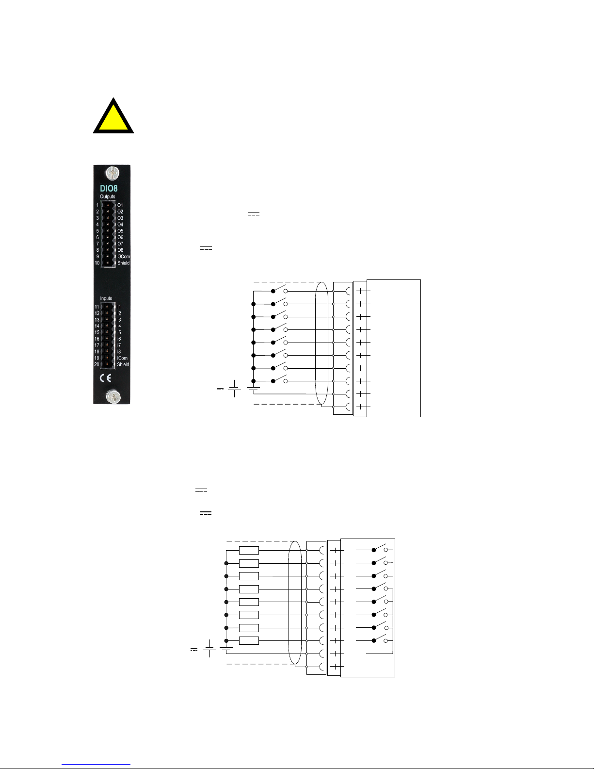
DIO8
The voltage levels on connectors of I/O modules shall not exceed
hazardous voltage levels of 30 Vrms, 42.4 Vpeak or 60 Vdc under
normal conditions. In wet locations these voltage levels shall not exceed
16 Vrms, 22.6 Vpeak or 35 Vdc.
Digital inputs
Terminals 11 – 18 and terminal 19 (ICom) as a common connection.
Eight digital inputs are provided, with functions that can be set
in the G4 set-up.
External sourcing (24 V
) from the instrument power supply
(max. 100 mA) or from a separate DC supply must be used.
Note that either the positive or the negative pole of the voltage
source (24 V
) can be connected to ICom (19).
Shielded cable/cables must be used, with the shield connected
to terminal 20.
I1
I2
I3
I4
I5
I6
I7
I8
ICom
Shield
-
+
+
11
12
13
14
15
16
17
18
19
20
24 V
Solid state relay outputs
Terminals 1 - 8 with terminal 9 (OCom) as a common connection.
Eight digital (relay) outputs are provided with contact rating given in Technical data.
External sourcing (24 V
) from the instrument power supply (max. 100 mA) or from a
separate DC supply must be used. Note that either the positive or the negative pole of
the voltage source (24 V
) can be connected to OCom (9).
Shielded cable/cables must be used, with the shield connected to terminal 10.
O1
O2
O3
O4
O5
O6
O7
O8
OCom
Shield
Load
Load
Load
Load
Load
Load
Load
Load
+
-
+
-
1
2
4
3
5
6
7
8
9
10
24 V
!
Page 29
G4 Multi Channel Force Instrument
2-11
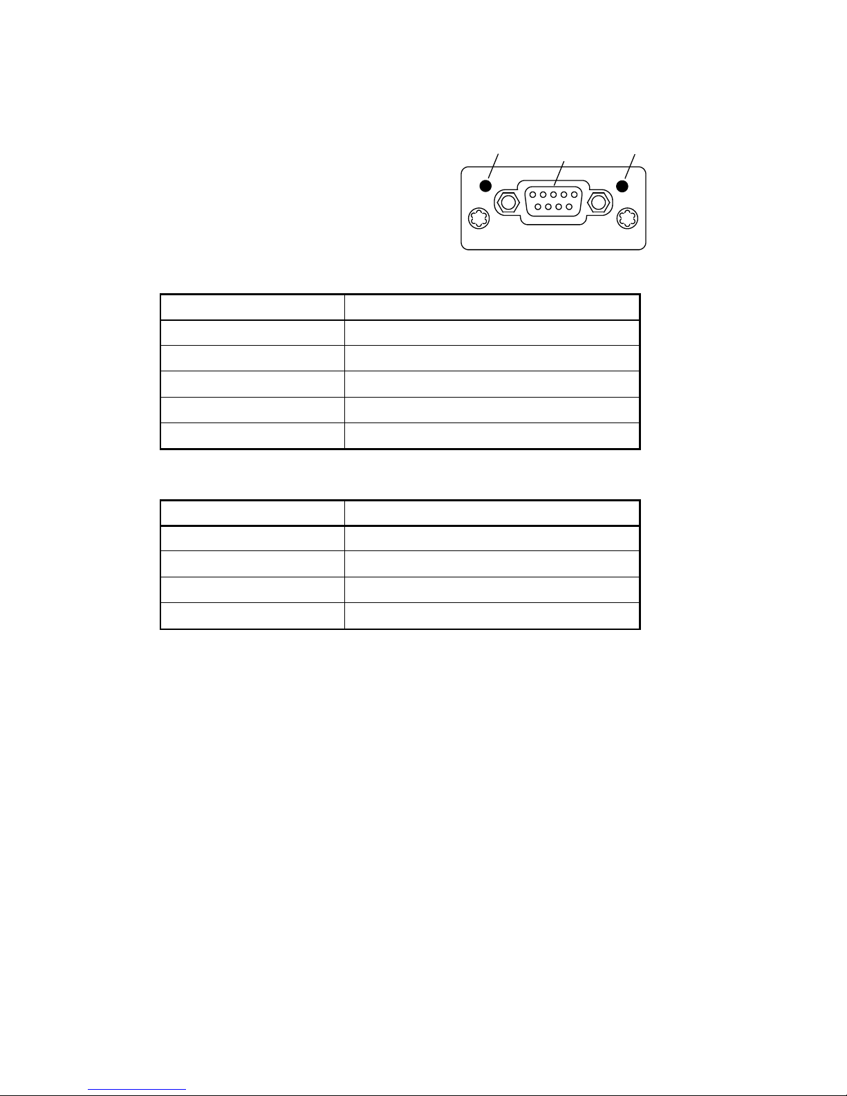
Profibus-DP Fieldbus Adaptor
Profibus module front view
(1) Operation mode LED.
(2) Status LED.
(3) Profibus connector.
Operation mode LED
State Indication
Off Not online / No power
Green On-line, data exchange
Flashing Green On-line, clear
Flashing Red (1 flash) Parameterization error
Flashing Red (2 flashes) Profibus configuration error
Status LED
State Indication
Off No power or not initialised
Green Initialised
Flashing Green Initialised, diagnostic event(s) present
Red Exception error
OP ST
PROFIBUS DP-V1
(1)
(2)
(3)
Page 30
Technical Manual
2-12
Profibus connector (DB9F)
Pin Signal Description
1 - -
2 - 3 B line Positive RxD/TxD, RS485 level
4 RTS Request to send
5 GND Bus Ground (isolated)
6 + 5V Bus Output +5V termination power (isolated)
7 - 8 A line Negative RxD/TxD, RS485 level
9 - Housing Cable shield Internally connected to the Anybus protective
earth via cable shield filters according to the
Profibus standard.
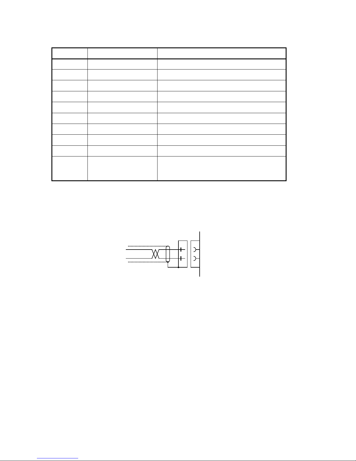
For connection of the adaptor to the Profibus master, use a Profibus standard cable
and connector according to the diagram below.
For reliable fieldbus function, line termination must be arranged in both ends of the
transmission line. For a G4 instrument, at the end of the cable, a connector with line
termination should be used. For all other G4 Instruments connection without line
termination should be used.
For configuration of the adaptor, a GSD file (VISH0AB3.GSD) is available and should
be installed in the master.
G4 Modular
Instrument
D-sub
A-line
B-line
8
3
shield
Page 31

G4 Multi Channel Force Instrument
2-13
DeviceNet Fieldbus Adaptor
DeviceNet module front view
(1) Network Status LED.
(2) Module Status LED.
(3) DeviceNet connector.
Network Status LED
State Indication
Off Not online / No power
Green On-line, one or more connections are established
Flashing Green (1 Hz) On-line, no connections established
Red Critical link failure
Flashing Red (1 Hz) One or more connections time out
Alternating Red/Green Self test
Module Status LED
State Indication
Off No power
Green Operating in normal condition
Flashing Green (1 Hz) Missing or incomplete configuration
Red Unrecoverable fault(s)
Flashing Red (1 Hz) Recoverable fault(s)
Alternating Red/Green Self test
NS MS
DeviceNet
(1)
(2)
(3)
(Pin 1)
Page 32

Technical Manual
2-14
DeviceNet connector
Pin Signal Description
1 V- Negative bus supply voltage
2 CAN L CAN low bus line
3 Shield Cable shield
4 CAN H CAN high bus line
5 V+ Positive bus supply voltage
For connection of the adaptor to the DeviceNet master, use a standard cable for
DeviceNet, or similar shielded cable with twisted pairs and a connector according to
the diagram below.
G4 Modular
Instrument
CAN L
2
4
shield
1
5
3
CAN H
V-
V+
For reliable fieldbus function, line termination must be arranged in both ends of the
transmission line. For a G4 instrument placed at the end of the line, terminate line by
placing a 121-ohm resistor between CAN L (pin 2) and CAN H (pin 4).
For configuration of the adaptor an EDS file is supplied with the instrument that should
be installed in the master. Note that the EDS file is a generic type supplied by the
module manufacturer. The file doesn’t contain any reference to the G4 Instrument or to
Nobel Weighing Systems.
Page 33

G4 Multi Channel Force Instrument
3-1
3. Instrument Functionality
General
This chapter describes the functionality of the different parts of the force instrument.
Function Block
All measuring functions in the instrument are based on configurable function blocks.
A Function Block is used to calculate the force or web tension of one to four inputs and
the sums and differences if more than one input is used. With a four channel Function
Block there are intermediate sum of force/web tension values calculated (A + B and
C + D).
The Function Block type is selected with parameter ‘Func.BlockX Type’ (Hardware
Configuration menu) and the value of the parameter can be set to ‘Not In Use’,
‘1 Channel’, ‘2 Channel’ or ‘4 Channel’. The type is selected individually for each used
Function Block.
A measuring channel, i.e. a connection on a WF IN / WF IN2 or HS WF2 module,
should be assigned to each Function Block input. The inputs of a Function Block are
named Input A to input D. Note that each measuring channel can only be assigned to
one Function Block input. Inputs cannot be shared between Function Blocks. The
maximum number of measuring channels in an instrument is 8 if WF IN2 modules are
used and 4 if HS WF2 modules are used.
A Function Block input can also be set to ‘Not In Use’ which means that the actual
input value used is always 0. This can be useful when using three transducers in a
4 channel Function Block or for testing purposes.
In the menu Param. Set-up – Calibration –
Function Block 1 (- 8) are parameters for configuration and
calibration located. Only used Function Blocks are displayed in
the menu.
The calibration parameters shown in the figure is for Function
Block 1.
There are sets of calibration parameters for each force input.
Parameters named ‘1:A …..’ belongs to input A, parameters
named ‘1:B …..’ belongs to input B and so on.
Calibration must be done for separately for each input.
All other parameters (‘1: …..’) are common for the whole
Function Block.
In the instrument and throughout this manual are outputs from
Function Blocks used for Display, Analog Outputs, Levels,
Communication, etc. These Output Signals are explained in the
tables below. The actual value for each “Output” is depending
on the Function Block type. E.g. if the sum of inputs C and D, on
a 4 channel Function Block, should be monitored on an analog
output, Output 2 should be chosen as the source for the analog
1:HSWF Update R.
800 Hz
1:Calibr. Type
Table
1:A ValueCal.P1
0 N
1:A T.Signal P1
0.00000 mV/V
1:A ValueCal.P2
1000 N
1:A T.Signal P2
2.00000 mV/V
1:A Set Zero
0.0 N
1:A Zero Offset
0.0 mV/V
1:B ValueCal.P1
0 N
1:B T.Signal P1
0.00000 mV/V
Page 34

Technical Manual
3-2
output. Also the input forces are available for monitoring etc, see ‘Common values’
later in this chapter.
Force Mode
The following table and figures explains the function and the values from a Function
Block in force mode (set-up parameter ‘X:Web T. Mode’ = Off).
A ‘(F)’ in the table below indicates a force value.
Value
1 Channel
Func. Block
2 Channel
Func. Block
4 Channel
Func. Block
Sum
Input A (F)
Input A+B (F)
Input A+B+C+D (F)
Difference
-
Input A-B (F)
Input (A+B) – (C+D) (F)
Output 1
Input A (F)
Input A (F)
Input A+B (F)
Output 2
-
Input B (F)
Input C+D (F)
Output 3
- - Input A (F)
Output 4
- - Input B (F)
Output 5
- - Input C (F)
Output 6
- - Input D (F)
Input A
Output 1
Sum
One Channel Function block, Force mode
Sum
Input A
Output 1
Input B Output 2
Difference
+
+
+
-
Two Channel Function block, Force mode
Input A
Sum
Output 3
Input B
Output 4
Output 1
Input C
Output 5
Input D Output 6
Output 2
Difference
+
+
+
+
+
+
+
-
Four Channel Function block, Force mode
Page 35

G4 Multi Channel Force Instrument
3-3
Web Tension Mode
A Function Block can be configured for web tension measuring by setting set-up
parameter ‘X:Web T. Mode’ to On. In this case some of the force values will be
recalculated to a web tension value using the ‘X:Web T. Factor’ as shown below.
Web Tension Value = Force Value / Web Tension Factor
If the Force Values are correctly calibrated in the desired measuring direction then the
‘Web T. Factor’ shall be set to the length of the roller (machine width) to get correct
Web Tension values, e.g. N/m. In other cases the ‘Web T. Factor’ must be calculated
based on calibration direction, web tension measuring direction, roller length, etc.
The following table and figures explains the function and the values from a Function
Block in web tension mode.
A ‘(F)’ in the table below indicates a force value and a ‘(WT)’ a web tension value.
Value
1 Channel
Func. Block
2 Channel
Func. Block
4 Channel
Func. Block
Sum
Input A (WT)
Input (A+B) / 2 (WT)
Input (A+B+C+D) / 2 (WT)
Difference
-
Input A-B (WT)
Input (A+B) – (C+D) (WT)
Output 1
Input A (WT)
Input A (WT)
Input A+B (WT)
Output 2
Input A (F)
Input B (WT)
Input C+D (WT)
Output 3
-
Input A (F)
Input A (F)
Output 4
-
Input B (F)
Input B (F)
Output 5
- - Input C (F)
Output 6
- - Input D (F)
Output 7
- - Input A+B (F)
Output 8
- - Input C+D (F)
Sum
Input A
1 / WTF
Output 2
Output 1
WTF = Web Tension Factor
One Channel Function block, Web Tension mode
Sum
Input A
1 / WTF
Output 3
Output 1
Input B
1 / WTF
Output 2
Output 4
Difference
1/2
+
+
+
-
WTF = Web Tension Factor
Two Channel Function block, Web Tension mode
Page 36

Technical Manual
3-4
Input A
Sum
Output 3
Input B
Output 4
1 / WTF
Output 7
Output 1
Input C
Output 5
Input D
Output 6
1 / WTF
Output 2
Output 8
Difference
1/2
+
+
+
+
+
+
+
-
WTF = Web Tension Factor
Four Channel Function block, Web Tension mode
Common values
The following table explains the available input values to a Function Block. These
values are the same for a Function Block both in force mode and tension mode.
Value
1 Channel
Func. Block
2 Channel
Func. Block
4 Channel
Func. Block
Input A Force
Inp. A Force
Inp. A Force
Inp. A Force
Input B Force
-
Inp. B Force
Inp. B Force
Input C Force
- - Inp. C Force
Input D Force
- - Inp. D Force
Input A Signal (mV/V)
Inp. A Signal
Inp. A Signal
Inp. A Signal
Input B Signal (mV/V)
-
Inp. B Signal
Inp. B Signal
Input C Signal (mV/V)
- - Inp. C Signal
Input D Signal (mV/V)
- - Inp. D Signal
Page 37

G4 Multi Channel Force Instrument
4-1
4. Set-up
General
All operating functions in the G4 Instrument are controlled by parameters. The
parameter values are permanently stored in the instrument and will not be lost when
the unit is switched off. At delivery the parameters are factory-set to default values,
giving the instrument an initial standard function.
The actual setting of the parameter values can be read and edited during normal
measuring operation in sub menu ‘Parameter Set-up’.
Editing of parameter values can be performed using the alphanumeric display and keys
on the front panel of the VIEWPAN module. After editing hardware parameters the
instrument will be restarted.
In the instrument there are two levels of security locks provided to protect from
unauthorized access to instrument functions and editing of parameters and values. The
locks are opened by four-digit codes.
Warning: Changes done during editing of set-up parameters will affect the behavior of
the instrument immediately. The user must take all necessary precautions to prevent
any undesired effects in the process monitored or controlled by the G4 instrument or a
connected control system.
It is strongly recommended to activate the set-up lock in the instrument to prevent any
unauthorized changes of set-up parameters.
It’s a good practice to make a backup of the set-up after changes have been done. See
chapter ‘8 Maintenance’ for more information on backup and restore.
The ‘Parameter Set-up’ menu contain the following sub menus:
General: This parameter group controls the general functionality of the instrument.
Such as display language, display contrast, security, key functions and so on.
Hardware Configuration: Parameters used for configuring the instrument hardware.
Here parameters that are used for basic configuration, of the Function blocks, found.
Note that when the instrument is starting up it will check that the installed hardware is
compatible with the settings. If not an alarm will be issued.
Calibration: Parameters that affect the behavior of the eight possible Function Blocks
in the instrument. There are parameters for calibration type, calibration values, filter
settings etc. All Function Blocks are individually settable.
Communication: Sub menus are Serial Com, Ethernet and Fieldbus.
Serial Com sub menu content is parameters used to set-up COM1 (RS232) and COM2
(RS485) on the CPU module. Parameters are among others: com. port mode, baud
rate and data format. Ethernet sub menu content is parameters for Modbus TCP
configuration. Fieldbus sub menu content is configuration parameters related to
fieldbus communication such as address, baud rate and transmitted data setup.
Level Supervision: The instrument has 32 level supervisors that are configured from
this sub menu. Settings for each level are which Function Block that the individual level
is to monitor and which signal that shall be monitored from the selected Function Block.
Signals that can be monitored are Sum value, Difference value, Output 1 and so on.
The output function e.g. if the output shall be active above or below the set level is
Page 38

Technical Manual
4-2
configured here. There are parameters for hystereses setting and level switching
delays.
Inputs: The use of the instruments digital inputs is set in this menu. Note that the
inputs are numbered 11 to 38. Inputs 11 to 18 corresponds to inputs on slot 1 I/O
module, 21 to 28 correspond to inputs on slot 2 I/O and so on. The actual number of
inputs depends on what type of I/O-module that is installed in the respective slots. A
DIO8 module has 8 inputs a WF IN2 module has 4 inputs while an AOUT1 or AOUT4
has no inputs. Inputs can be used for zeroing of Function Blocks.
Outputs: The outputs menu contains the settings controlling the function of each
output. Numbering is 11 to 38 for the I/O module outputs. See section ‘Inputs’ above on
how individual output numbers correspond to each I/O slot. Each output can be
assigned an output function: Level output status or ‘In Process’ status.
Analog Outputs: This menu controls the behavior of an AOUT4 or an AOUT1 Analog
output module. The output signal source (Function Block No and signal type) can be
selected. Also output type and range high/low is settable.
Operators interface
The DIN-rail type of instrument uses the service
panel (VIEWPAN) located in the I/O slot system of
the instrument as operator interface. It also
includes a 24 VDC power supply that supports the
complete instrument with power. The VIEWPAN
module occupies slots 4 to 6.
It is also possible to connect a standard USB
keyboard for PC to the USB connector
at the CPU module. The keyboard will work in
parallel with the keys on VIEWPAN and will make
it easier to handle the configuration of the
instrument, as it can be used as an input for digits
and characters.
The keyboard keys ' + ', ' - ', ' ↑ ' or 'Esc', and
'Enter' will correspond the VIEWPAN keys ' + ',
' - ', ' ↑ ' , and ' ↵ '.
Function key 'F11' on the keyboard can be used
to access the 'Main Menu'.
ViewPan module
Page 39

G4 Multi Channel Force Instrument
4-3
From any of the operating display views, displaying the main menu is done by pressing
‘+’ and ‘↑’ keys simultaneously for 1 second.
The ViewPan ‘+’ and ‘−’ keys are used to scroll the available menu items and the ‘↵’
key is used to enter the selected sub menu. Pressing the ‘↑’ key when in the main
menu will make the instrument display the operating menu.
To move one step back in the menu structure press the ‘↑’ key. The ‘↑’ key is also used
to cancel any parameter editing.
1: 385 N
20
Main Menu
Levels
Main Menu
Clock Set-up
+
-
+
+ 1 second
+
Levels Menu
Clock Set-up
Menu
Main Menu
Param. Set-up
-
+
Parameter Set-
up Menu
Main Menu
System Info.
-
+
System Info
Menu
Main Menu
Maintenance
-
Maintenance Menu
+
Main Menu
Network Config
-
Network Config
Menu
ViewPan main menu
Page 40

Technical Manual
4-4
Parameter Set-up menu
To enter a Parameter Set-up sub menu the
desired one is selected by scrolling with ‘+’ or ‘−’
keys until it’s shown. Then the sub menu is
entered by pressing ‘↵’. Returning to ‘Main
Menu’ from ‘Parameter Set-up’ menu is done by
pressing the ‘↑’ key.
Main Menu
Param. Set-up
Param. Set-up
General
Param. Set-up
Hardware Config.
+
-
Param. Set-up
Calibration
+
-
+
Param. Set-up
Communication
-
+
Param. Set-up
Level Superv.
-
+
Param. Set-up
Inputs
-
+
Param. Set-up
Outputs
-
+
Param. Set-up
Analog Outputs
-
Parameter set-up menu
Page 41

G4 Multi Channel Force Instrument
4-5
Parameter editing procedure
This example shows the ‘General’
parameter menu but editing is done similar
throughout the menu system.
The desired menu is selected by scrolling
with ‘+’ or ‘−’ keys until it is shown. Then the
sub menu is entered by pressing ‘↵’.
Returning to previous menu from a sub
menu is done by pressing the ‘↑’ key.
The desired parameter is selected by
scrolling with ‘+’ or ‘−’ keys until it is shown.
As the wanted set-up parameter is
displayed, press ‘↵’ to start the editing
procedure. This will place a flashing cursor
to the left on the lower line, and a numerical
parameter value will get leading zeros. The
cursor indicates that editing can be
performed and that the panel key functions
are different.
+ Key function:
Increment the cursor digit, or go to next
alternative in case of a choice parameter.
−
Key function:
Decrement the cursor digit, or go to
previous alternative in case of a choice
parameter.
↵ Key function (short press):
Accept the value of the cursor digit and go
to next digit.
↵ Key function (1 sec press):
Accept the actual parameter value and
finish editing. If a value outside the range for
a numeric parameter is entered, an error
message is displayed. Then press any key
to remove the message and make
continued editing possible.
↑
Key function:
Cancel the edited value, and interrupt the
editing.
Parameter set-up
General
Language
English
Instrument Name
+
-
Start Mode
Auto
+
-
+
Display Contrast
6
-
+
Date Format
YYYY-MM-DD
-
+
Time Format
24 h
-
+
Zero key
Off
-
+
Operator Lock
On
-
+
Operator Code
****
-
+
Set-up Lock
On
-
+
Set-up Code
****
-
Edit
parameter
Edit
parameter
Edit
parameter
Edit
parameter
Edit
parameter
Edit
parameter
Edit
parameter
Edit
parameter
Edit
parameter
Edit
parameter
Edit
parameter
’General’ parameters menu
Page 42

Technical Manual
4-6
Menu structure
(Cont. on next
page)
Main Menu
*Levels
*Clock Set-up
*Param. Set-up
*System Info.
*Maintenance
*Network Config
Param. Set-up
*General
*Hardware Config.
*Calibration
*Communication
*Level Superv.
*Inputs
*Outputs
*Analog Outputs
General
Language
Instrument Name
Start Mode
Display Contrast
Date Format
Time Format
Zero Key
Operator Lock
Operator Code
Set-up Lock
Set-up Code
Hardware Config.
Fieldbus
Slot 1 Module
Slot 2 Module
Slot 3 Module
Func.Block1 Type
F.Block 1 Inp.A
F.Block 1 Inp.B
F.Block 1 Inp.C
F.Block 1 Inp.D
Func.Block2 Type
F.Block 2 Inp.A
F.Block 2 Inp.B
F.Block 2 Inp.C
F.Block 2 Inp.D
Func.Block3 Type
F.Block 3 Inp.A
F.Block 3 Inp.B
F.Block 3 Inp.C
F.Block 3 Inp.D
Func.Block4 Type
F.Block 4 Inp.A
F.Block 4 Inp.B
F.Block 4 Inp.C
F.Block 4 Inp.D
Func.Block5 Type
F.Block 5 Inp.A
F.Block 5 Inp.B
F.Block 5 Inp.C
F.Block 5 Inp.D
Func.Block6 Type
F.Block 6 Inp.A
F.Block 6 Inp.B
F.Block 6 Inp.C
F.Block 6 Inp.D
Func.Block7 Type
F.Block 7 Inp.A
F.Block 7 Inp.B
F.Block 7 Inp.C
F.Block 7 Inp.D
Func.Block8 Type
F.Block 8 Inp.A
F.Block 8 Inp.B
F.Block 8 Inp.C
F.Block 8 Inp.D
Calibration
*Function Block 1
*Function Block 2
*Function Block 3
*Function Block 4
*Function Block 5
*Function Block 6
*Function Block 7
*Function Block 8
Function Block 1..8
1:Func.BlockName
1:Web T. Mode
1:Measurem. Unit
1:Resolution
1:Web T.Unit
1:Web T.Resol.
1:Web T.Factor
1:HSWF Update R.
1:WFIN Update R.
1:Calibr. Type
1:A ValueCal.P1
1:A T. Signal P1
1:A ValueCal.P2
1:A T. Signal P2
1:A Set Zero
1:A Zero Offset
1:B ValueCal.P1
1:B T. Signal P1
1:B ValueCal.P2
1:B T. Signal P2
1:B Set Zero
1:B Zero Offset
1:C ValueCal.P1
1:C T. Signal P1
1:C ValueCal.P2
1:C T. Signal P2
1:C Set Zero
1:C Zero Offset
1:D ValueCal.P1
1:D T. Signal P1
1:D ValueCal.P2
1:D T. Signal P2
1:D Set Zero
1:D Zero Offset
*sub menu
Levels
Level values for
configured levels
Clock Set-up
Date and time set-up
(Cont. on next page)
Menu structure (continued)
Page 43

G4 Multi Channel Force Instrument
4-7
Inputs
*Inputs Slot 1
*Inputs Slot 2
*Inputs Slot 3
Outputs
*Outputs Slot 1
*Outputs Slot 2
*Outputs Slot 3
Analog Outputs
AOUT1 Source
AOUT1 F.Block
AOUT1 Outp.Type
AOUT1 Range Low
AOUT1 Range High
AOUT1 Bandwidth
AOUT1 Low Adj.
AOUT1 High Adj.
AOUT2 Source
AOUT2 F.Block
AOUT2 Outp.Type
AOUT2 Range Low
AOUT2 Range High
AOUT2 Bandwidth
AOUT2 Low Adj.
AOUT2 High Adj
AOUT3 Source
AOUT3 F.Block
AOUT3 Outp.Type
AOUT3 Range Low
AOUT3 Range High
AOUT3 Bandwidth
AOUT3 Low Adj.
AOUT3 High Adj.
AOUT4 Source
AOUT4 F.Block
AOUT4 Outp.Type
AOUT4 Range Low
AOUT4 Range High
AOUT4 Bandwidth
AOUT4 Low Adj.
AOUT4 High Adj.
(from previous page)
Inputs Slot 1..3
Input 11 Use
Input 11 F.Block
Input 12 Use
Input 12 F.Block
…….
Input 18 Use
Input 18 F.Block
Outputs Slot 1..3
Outp. 11 Source
Output 11 Level
Outp. 12 Source
Output 12 Level
…….
Outp. 18 Source
Output 18 Level
(from previous page)
System Info.
Information on serial
numbers, program
versions, network
status and installed
I/O modules.
Maintenance
*Diagnostics
*File Handling
*Create Backup
*Restore Backup
*Set Default
*Program Upgrade
Network Config
*IP Config.
*Server Config.
Level Superv.
*Level 1
*Level 2
*Level 3
…….
*Level 31
*Level 32
Level 1..32
Level 1 Source
Level 1 Mode
Level 1 F.Block
Level 1 Output
Level 1 Hyst.
Level 1 Up Del.
Level 1 Dn.Del.
Communication
Modbus Address
COM1:Mode
COM1:Baudrate
COM1:Data Format
COM1:Min Reply T
COM1:Float Form.
COM2:Mode
COM2:Baudrate
COM2:Data Format
COM2:Min Reply T
COM2:Float Form.
Modbus TCP Slave
Float Format
Serial Com.
Ethernet
*Serial Com.
*Ethernet
*Fieldbus
Address
Baudrate
No of Data Block
Block 1 Type
Block 1 Format
Block 1 FB
Block 2 Type
Block 2 Format
Block 2 FB
Block 3 Type
Block 3 Format
Block 3 FB
…….
Block 11 Type
Block 11 Format
Block 11 FB
Block 12 Type
Block 12 Format
Block 12 FB
Fieldbus
(continued) Menu structure
Page 44

Technical Manual
4-8
Parameters
On the following pages a survey of all parameters is presented. The parameters are
divided in groups following the menu they belong to. For choice parameters the
available choices are given. For numerical parameters, a value range is given.
At the end of the table, the default value is given in < >.
To the right there is a short parameter explanation and, in italic, the results for
the different alternatives.
Range/Alternatives Explanation and
<default value> result of alternatives.
Menu ‘General’
Language
English
Svenska
<English>
Defines the language to be used in menus and messages.
Instrument Name
<> A 16-character string that is used at printing in reports and so
on.
Start Mode
Command
Auto
<Auto>
Defines the start mode after power-on or reset.
Command: A ‘start operation’ command from
control computer or panel key is required for start up.
Auto: Automatic start up.
Display Contrast
0
1
2
3
4
5
6
7
<5>
Defines the text contrast for the alphanumerical display.
Low values giving lower contrast.
High values giving sharper characters but reduced readability
at slanted display.
Date Format
YYYY-MM-DD
YYYY-DD-MM
DD-MM-YYYY
MM/DD/YYYY
<YYYY-MM-DD>
Defines the date format.
YYYY: = year. MM: = month. DD: = day.
Page 45

G4 Multi Channel Force Instrument
4-9
Range/Alternatives Explanation and
<default value> resul t of al ternatives.
Time Format
12 h
24 h
<24h>
Defines the time format.
12 h: 12 hour time format.
24 h: 24 hour time format.
Zero Key
Off
On
<Off>
Disables/enables the Zero function from the front panel.
Off: The Zero function is disabled.
On: The Zero function is enabled.
Operator Lock
Off
On
<Off>
Off: Operator lock is not activated.
On: Operator lock is activated, preventing unauthorized access
to the instrument.
See chapter 6 ‘Operation − Security locks’
Operator Code
Range:
1 - 9999
<1937>
Defines the valid code for Operator lock.
If ‘Set-up lock’ (see below) is ‘On’ this code will not give access
to functions that requires the ‘Set-up Code’.
Note: this parameter is only shown if ‘Operator Lock’ is set to
‘On’
Set-up Lock
Off
On
<Off>
Off: Set-up lock is not activated.
On: Operator lock is activated, preventing unauthorized access
to the instrument.
See chapter 6 ‘Operation − Security locks’
Set-up Code
Range:
1 - 9999
<1937>
Defines the valid code for Set-up lock.
If ‘Operator lock’ (see above) is ‘On’ this code will still give
access to all menus in the Main menu.
Note: this parameter is only shown if ‘Set-up Lock‘ is set to ‘On’
Page 46

Technical Manual
4-10
Range/Alternatives Explanation and
<default value> resul t of al ternatives.
Menu ‘Hardware Config.’
Fieldbus
Not In Use
Profibus
DeviceNet
<Not In Use>
This parameter defines what type of fieldbus that will be used in
the CPU.
Not In Use: The fieldbus is not used regardless of any installed
module.
Profibus: A Profibus type of fieldbus module is used.
DeviceNet: A DeviceNet type of fieldbus module is used.
Slot 1 Module
No module
HSWF2
WFIN
WFIN2
AOUT1
AOUT4
DIO8
<WFIN2>
This parameter defines what type of I/O-module is installed in
slot 1.
No module: No module is used in this slot.
HSWF2: A 2 channel high speed weight/force module.
WFIN: A 1 channel, weight/force measuring module.
WFIN2: A 2 channel, weight/force measuring module.
AOUT1: A 1 channel analog output module.
AOUT4: A 4 channel analog output module.
DIO8: A 8/8 digital input/output module.
Slot 2 Module
< No module > This parameter defines what type of I/O- module is installed in
slot 2. See ‘Slot 1 Module type’ for details on parameter values.
Slot 3 Module
< No module > This parameter defines what type of I/O- module is installed in
slot 3. See ‘Slot 1 Module type’ for details on parameter values.
Func.Block1 Type
Not In Use
1 Channel
2 Channel
4 Channel
< 1 Channel >
This parameter defines if Function Block 1 is used and, if used,
the no of inputs it should use.
Not In Use: The Function Block is not used.
1 Channel: 1 channel type.
2 Channel: 2 channel type.
4 Channel: 4 channel type.
Page 47

G4 Multi Channel Force Instrument
4-11
Range/Alternatives Explanation and
<default value> resul t of al ternatives.
F.Block 1 Inp.A
Not In Use
Slot 1, Ch 1
Slot 1, Ch 2
Slot 2, Ch 1
Slot 2, Ch 2
Slot 3, Ch 1
Slot 3, Ch 2
(Slot 4, Ch 1)
(Slot 4, Ch 2)
(Slot 5, Ch 1)
(Slot 5, Ch 2)
(Slot 6, Ch 1)
(Slot 6, Ch 2)
< Slot 1, Ch 1 >
This parameter defines which measuring channel (slot and
channel) that should be use as input A to Function Block 1.
Not In Use: The input is not used
Slot 1, Ch 1: Use measuring channel 1 of slot 1
Slot 1, Ch 2: Use measuring channel 2 of slot 1
Slot 2, Ch 1: Use measuring channel 1 of slot 2
Slot 2, Ch 2: Use measuring channel 2 of slot 2
Slot 3, Ch 1: Use measuring channel 1 of slot 3
Slot 3, Ch 2: Use measuring channel 2 of slot 3
Note: selection of ‘Slot 4, Ch 1’ to ‘Slot 6, Ch 2’ not allowed in
the RM type of instrument.
Note: this parameter is not shown if ‘Function Block 1 Type’ is
‘Not In Use’.
F.Block 1 Inp.B
Not In Use
Slot 1, Ch 1
Slot 1, Ch 2
Slot 2, Ch 1
Slot 2, Ch 2
Slot 3, Ch 1
Slot 3, Ch 2
(Slot 4, Ch 1)
(Slot 4, Ch 2)
(Slot 5, Ch 1)
(Slot 5, Ch 2)
(Slot 6, Ch 1)
(Slot 6, Ch 2)
< Not In Use >
This parameter defines which measuring channel (slot and
channel) that should be use as input B to Function Block 1.
See ‘F.Block 1 Inp. A.’ for a description of parameter values.
Note: this parameter is only shown if ‘Function Block 1 Type’ is
‘2 Channel’ or ‘4 Channel’.
F.Block 1 Inp.C
< Not In Use > This parameter defines which measuring channel (slot and
channel) that should be use as input C to Function Block 1.
See ‘F.Block 1 Inp. A.’ for a description of parameter values.
Note: this parameter is only shown if ‘Function Block 1 Type’ is
‘4 Channel’.
F.Block 1 Inp.D
< Not In Use > This parameter defines which measuring channel (slot and
channel) that should be use as input D to Function Block 1.
See ‘F.Block 1 Inp. A.’ for a description of parameter values.
Note: this parameter is only shown if ‘Function Block 1 Type’ is
‘4 Channel’.
Page 48

Technical Manual
4-12
Range/Alternatives Explanation and
<default value> resul t of al ternatives.
Func.Block2 Type
Not In Use
1 Channel
2 Channel
4 Channel
< 1 Channel >
This parameter defines if Function Block 2 is used and, if used,
the no of inputs it should use.
Not In Use: The Function Block is not used.
1 Channel: 1 channel type.
2 Channel: 2 channel type.
4 Channel: 4 channel type.
F.Block 2 Inp.A
< Slot 1, Ch 2 > This parameter defines which measuring channel (slot and
channel) that should be used as input A to Function Block 2.
See ‘F.Block 1 Inp. A.’ for a description of parameter values.
Note: this parameter is not shown if ‘Function Block 2 Type’ is
‘Not In Use’.
F.Block 2 Inp.B
< Not In Use > This parameter defines which measuring channel (slot and
channel) that should be used as input B to Function Block 2.
See ‘F.Block 1 Inp. A.’ for a description of parameter values.
Note: this parameter is only shown if ‘Function Block 2 Type’ is
‘2 Channel’ or ‘4 Channel’.
F.Block 2 Inp.C
< Not In Use > This parameter defines which measuring channel (slot and
channel) that should be used as input C to Function Block 2.
See ‘F.Block 1 Inp. A.’ for a description of parameter values.
Note: this parameter is only shown if ‘Function Block 2 Type’ is
‘4 Channel’.
F.Block 2 Inp.D
< Not In Use > This parameter defines which measuring channel (slot and
channel) that should be used as input D to Function Block 2.
See ‘F.Block 1 Inp. A.’ for a description of parameter values.
Note: this parameter is only shown if ‘Function Block 2 Type’ is
‘4 Channel’.
Page 49

G4 Multi Channel Force Instrument
4-13
Range/Alternatives Explanation and
<default value> resul t of al ternatives.
Func.Block3 Type
Not In Use
1 Channel
2 Channel
4 Channel
< Not In Use >
This parameter defines if Function Block 3 is used and, if used,
the no of inputs it should use.
Not In Use: The Function Block is not used.
1 Channel: 1 channel type.
2 Channel: 2 channel type.
4 Channel: 4 channel type.
F.Block 3 Inp.A
< Not In Use > This parameter defines which measuring channel (slot and
channel) that should be used as input A to Function Block 3.
See ‘F.Block 1 Inp. A.’ for a description of parameter values.
Note: this parameter is not shown if ‘Function Block 3 Type’ is
‘Not In Use’.
F.Block 3 Inp.B
< Not In Use > This parameter defines which measuring channel (slot and
channel) that should be used as input B to Function Block 3.
See ‘F.Block 1 Inp. A.’ for a description of parameter values.
Note: this parameter is only shown if ‘Function Block 3 Type’ is
‘2 Channel’ or ‘4 Channel’.
F.Block 3 Inp.C
< Not In Use > This parameter defines which measuring channel (slot and
channel) that should be used as input C to Function Block 3.
See ‘F.Block 1 Inp. A.’ for a description of parameter values.
Note: this parameter is only shown if ‘Function Block 3 Type’ is
‘4 Channel’.
F.Block 3 Inp.D
< Not In Use > This parameter defines which measuring channel (slot and
channel) that should be used as input D to Function Block 3.
See ‘F.Block 1 Inp. A.’ for a description of parameter values.
Note: this parameter is only shown if ‘Function Block 3 Type’ is
‘4 Channel’.
For an explanation of parameters for Function Blocks 4 to 8 see:
‘Func.Block3 Type’
‘F.Block 3 Inp.A.’
‘F.Block 3 Inp.B.’
‘F.Block 3 Inp.C.’
‘F.Block 3 Inp.D.’
Note that the parameters for a Function Block are shown or not shown depending on
the setting of parameter ‘Func. Block X Type’, for that specific Function Block.
Page 50

Technical Manual
4-14
Range/Alternatives Explanation and
<default value> resul t of al ternatives.
Menus ‘Function Block 1’ – ‘Function Block 8’
The Calibration menu contains up to 6 sub menus, one for each used Function Block.
The parameters are the same for all 6 menus. Here only Function Block 1 parameters
are shown. Note that the Function Block number is shown as a prefix to the parameter
name, here ‘1:’ Also note that the menu is only shown if the parameter
‘Func. Block X Type’, for the actual Function Block, is not set to ‘Not In Use’.
1:Func.BlockName
<> A 16-character string that is used at printing, in reports etc.
1:Web T. Mode
Off
On
<Off>
Selects Force or Web Tension mode for the Function Block.
Off: Force mode.
On: Web Tension Mode.
1:Measurem. Unit
NONE
N
daN
kN
MN
lbf
kgf
Nm
N/m
kN/m
PLI
g
kg
t
lb
oz
psi
kPa
MPa
bar
l
mm
m
inch
feet
st
pcs
%
mV/V
<N>
Defines the unit that should be used for measured force value(s)
and for related set-up parameters.
Page 51

G4 Multi Channel Force Instrument
4-15
Range/Alternatives Explanation and
<default value> resul t of al ternatives.
1:Resolution
0.001
0.002
0.005
0.01
0.02
0.05
0.1
0.2
0.5
1
2
5
10
20
50
<1>
Defines the decimal point position and resolution format for the
displayed force value. All set-up parameters using the
measurement unit will be written with the decimal point position
selected in this menu.
If the last digits of the displayed value are not stable, a more
coarse resolution can be selected to get a stable reading.
1:Web T.Unit
NONE
N/m
kN/m
PLI
%
<N/m>
Defines the unit that should be used for measured web tension
value(s) and for related set-up parameters.
Note: this parameter is only shown if ‘1:Web Tension Mode‘ is
set to ‘On’
1:Web T. Resol.
0.001
0.002
0.005
0.01
0.02
0.05
0.1
0.2
0.5
1
2
5
10
20
50
<1>
Defines the decimal point position and resolution format for the
displayed web tension value. All set-up parameters using the
web tension unit will be written with the decimal point position
selected in this menu.
If the last digits of the displayed value are not stable, a more
coarse resolution can be selected to get a stable reading.
Note: this parameter is only shown if ‘1:Web Tension Mode‘ is
set to ‘On’
1:Web T.Factor
Range: +/–999999
<1.00000>
This parameter defines the relations between a measured Force
value and a Web Tension value.
See chapter 3 ‘Instrument Functionality − Function Block −
Web Tension Mode’
Note: this parameter is only shown if ‘1:Web Tension Mode‘ is
set to ‘On’
Page 52

Technical Manual
4-16
Range/Alternatives Explanation and
<default value> resul t of al ternatives.
1:HSWF Update R.
25 Hz
50 Hz
100 Hz
200 Hz
400 Hz
800 Hz
800 Hz ++
<800 Hz>
Defines the update rate for the measuring channel belonging to
Function Block 1 if the force conversion module is of HS WF 2
type.
Note: this parameter is only shown if the force conversion
module belonging to this Function Block 1 is of HS WF2 type.
1:WFIN Update R.
9.3 Hz
19 Hz
37 Hz
75 Hz
150 Hz
300 Hz
300 Hz ++
<300 Hz>
Defines the update rate for the measuring channel belonging to
Function Block 1 if the force conversion module is of WF IN or
WF IN2 type.
Note: this parameter is only shown if the force conversion
module belonging to Function Block 1 is of WF IN or WF IN2
type.
1:Calibr. Type
Known Force
Table
< Table >
Defines the type of calibration to be performed. A new
calibration is initiated as a ‘Calibration type’ is selected and
Enter key pressed.
Known Force: Known Force calibration is normally
the most accurate calibration type. It is recommended to load
with at least 2/3 of the used range.
Table: Table calibration is used when calibrating with data from
transducer calibration data sheet or when entering recorded
values from a previous calibration into a replacement instrument.
Page 53

G4 Multi Channel Force Instrument
4-17
Range/Alternatives Explanation and
<default value> resul t of al ternatives.
1:A ValueCal.P1
Range: +/–999999
Unit:
Measurement Unit
<0>
This parameter defines, for Input A, the load in the lowest
calibration point, normally 0.
The live force will be displayed when the enter button is pressed.
Press the enter button a second time to edit the value.
Note: This parameter is not shown if parameter ‘F.Block 1 Inp.A’
is set to ‘Not In Use’.
1:A T.Signal P1
Range: +/–9.99999
Unit: mV/V
<0.00000>
This parameter defines the transducer signal, for Input A, in the
lowest calibration point.
Note: This parameter value is automatically acquired, and
cannot be edited, if ‘1:Calibration Type’ is set to ‘Known Force’.
It is not shown if parameter ‘F.Block 1 Inp.A’ is set to
‘Not In Use’.
1:A ValueCal.P2
Range: +/–999999
Unit:
Measurement Unit
<1000>
This parameter defines, for Input A, the load in the second
calibration point.
The live force will be displayed when the enter button is pressed.
Press the enter button a second time to edit the value.
Note: This parameter is not shown if parameter ‘F.Block 1 Inp.A’
is set to ‘Not In Use’.
1:A T.Signal P2
Range: +/–9.99999
Unit: mV/V
<2.00000>
This parameter defines the transducer signal, for Input A, in the
second calibration point.
Note: This parameter value is automatically acquired, and
cannot be edited, if ‘1:Calibration Type’ is set to ‘Known Force’.
It is not shown if parameter ‘F.Block 1 Inp.A’ is set to
‘Not In Use’.
1:A Set Zero
Range +/-999999
Unit:
Measurement Unit
< 0 >
This parameter is used to zero input A for Function Block 1.
Enter wanted value for the actual force on Input A, usually ’0’,
i.e. unloaded transducer.
The live force will be displayed when the enter button is pressed.
Press the enter button a second time to edit the zeroing value.
Note: This parameter is not shown if parameter ‘F.Block 1 Inp.A’
is set to ‘Not In Use’.
1:A Zero Offset
Range +/-999999
Unit:
Measurement Unit
< 0 >
This parameter shows the offset value acquired, for Input A, by
zeroing with ‘1:A Set Zero’. If this parameter is edited, the
zeroing of Input A will be influenced.
Note: This parameter is not shown if parameter ‘F.Block 1 Inp.A’
is set to ‘Not In Use’.
Page 54

Technical Manual
4-18
Range/Alternatives Explanation and
<default value> resul t of al ternatives.
1:B ValueCal.P1
Range: +/–999999
Unit:
Measurement Unit
<0>
This parameter defines, for Input B, the load in the lowest
calibration point, normally 0.
The live force will be displayed when the enter button is pressed.
Press the enter button a second time to edit the value.
Note: This parameter is only shown if parameter
‘Func. Block 1 Type’ is set to ‘2 channel’ or ‘4 Channel’ and
‘F.Block 1 Inp.B’ is not set to ‘Not In Use’.
1:B T.Signal P1
Range: +/–9.99999
Unit: mV/V
<0.00000>
This parameter defines the transducer signal, for Input B, in the
lowest calibration point.
Note: This parameter value is automatically acquired, and
cannot be edited, if ‘1:Calibration Type’ is set to ‘Known Force’.
It is only shown if parameter ‘Func. Block 1 Type’ is set to
‘2 channel’ or ‘4 Channel’ and ‘F.Block 1 Inp.B’ is not set to
‘Not In Use’.
1:B ValueCal.P2
Range: +/–999999
Unit:
Measurement Unit
<1000>
This parameter defines, for Input B, the load in the second
calibration point.
The live force will be displayed when the enter button is pressed.
Press the enter button a second time to edit the value.
Note: This parameter is only shown if parameter
‘Func. Block 1 Type’ is set to ‘2 channel’ or ‘4 Channel’ and
‘F.Block 1 Inp.B’ is not set to ‘Not In Use’.
1:B T.Signal P2
Range: +/–9.99999
Unit: mV/V
<2.00000>
This parameter defines the transducer signal, for Input B, in the
second calibration point.
Note: This parameter value is automatically acquired, and
cannot be edited, if ‘1:Calibration Type’ is set to ‘Known Force’.
It is only shown if parameter ‘Func. Block 1 Type’ is set to
‘2 channel’ or ‘4 Channel’ and ‘F.Block 1 Inp.B’ is not set to
‘Not In Use’.
1:B Set Zero
Range +/-999999
Unit:
Measurement Unit
< 0 >
This parameter is used to zero input B for Function Block 1.
Enter wanted value for the actual force on Input B, usually ’0’,
i.e. unloaded transducer.
The live force will be displayed when the enter button is pressed.
Press the enter button a second time to edit the zeroing value.
Note: This parameter is only shown if parameter
‘Func. Block 1 Type’ is set to ‘2 channel’ or ‘4 Channel’ and
‘F.Block 1 Inp.B’ is not set to ‘Not In Use’.
1:B Zero Offset
Range +/-999999
Unit:
Measurement Unit
< 0 >
This parameter shows the offset value acquired, for Input B, by
zeroing with ‘1:B Set Zero’. If this parameter is edited, the
zeroing of Input B will be influenced.
Note: This parameter is only shown if parameter
‘Func. Block 1 Type’ is set to ‘2 channel’ or ‘4 Channel’ and
‘F.Block 1 Inp.B’ is not set to ‘Not In Use’.
Page 55

G4 Multi Channel Force Instrument
4-19
Range/Alternatives Explanation and
<default value> resul t of al ternatives.
1:C ValueCal.P1
Range: +/–999999
Unit:
Measurement Unit
<0>
This parameter defines, for Input C, the load in the lowest
calibration point, normally 0.
The live force will be displayed when the enter button is pressed.
Press the enter button a second time to edit the value.
Note: This parameter is only shown if parameter
‘Func. Block 1 Type’ is set to ‘4 Channel’ and ‘F.Block 1 Inp.C’ is
not set to ‘Not In Use’.
1:C T.Signal P1
Range: +/–9.99999
Unit: mV/V
<0.00000>
This parameter defines the transducer signal, for Input C, in the
lowest calibration point.
Note: This parameter value is automatically acquired, and
cannot be edited, if ‘1:Calibration Type’ is set to ‘Known Force’.
It is only shown if parameter ‘Func. Block 1 Type’ is set to
‘4 Channel’ and ‘F.Block 1 Inp.C’ is not set to ‘Not In Use’.
1:C ValueCal.P2
Range: +/–999999
Unit:
Measurement Unit
<1000>
This parameter defines, for Input C, the load in the second
calibration point.
The live force will be displayed when the enter button is pressed.
Press the enter button a second time to edit the value.
Note: This parameter is only shown if parameter
‘Func. Block 1 Type’ is set to ‘4 Channel’ and ‘F.Block 1 Inp.C’ is
not set to ‘Not In Use’.
1:C T.Signal P2
Range: +/–9.99999
Unit: mV/V
<2.00000>
This parameter defines the transducer signal, for Input C, in the
second calibration point.
Note: This parameter value is automatically acquired, and
cannot be edited, if ‘1:Calibration Type’ is set to ‘Known Force’.
It is only shown if parameter ‘Func. Block 1 Type’ is set to
‘4 Channel’ and ‘F.Block 1 Inp.C’ is not set to ‘Not In Use’.
1:C Set Zero
Range +/-999999
Unit:
Measurement Unit
< 0 >
This parameter is used to zero input C for Function Block 1.
Enter wanted value for the actual force on Input C, usually ’0’,
i.e. unloaded transducer.
The live force will be displayed when the enter button is pressed.
Press the enter button a second time to edit the zeroing value.
Note: This parameter is only shown if parameter
‘Func. Block 1 Type’ is set to ‘4 Channel’ and ‘F.Block 1 Inp.C’ is
not set to ‘Not In Use’.
1:C Zero Offset
Range +/-999999
Unit:
Measurement Unit
< 0 >
This parameter shows the offset value acquired, for Input C, by
zeroing with ‘1:C Set Zero’. If this parameter is edited, the
zeroing of Input C will be influenced.
Note: This parameter is only shown if parameter
‘Func. Block 1 Type’ is set to ‘4 Channel’ and ‘F.Block 1 Inp.C’ is
not set to ‘Not In Use’.
Page 56

Technical Manual
4-20
Range/Alternatives Explanation and
<default value> resul t of al ternatives.
1:D ValueCal.P1
Range: +/–999999
Unit:
Measurement Unit
<0>
This parameter defines, for Input D, the load in the lowest
calibration point, normally 0.
The live force will be displayed when the enter button is pressed.
Press the enter button a second time to edit the value.
Note: This parameter is only shown if parameter
‘Func. Block 1 Type’ is set to ‘4 Channel’ and ‘F.Block 1 Inp.D’ is
not set to ‘Not In Use’.
1:D T.Signal P1
Range: +/–9.99999
Unit: mV/V
<0.00000>
This parameter defines the transducer signal, for Input D, in the
lowest calibration point.
Note: This parameter value is automatically acquired, and
cannot be edited, if ‘1:Calibration Type’ is set to ‘Known Force’.
It is only shown if parameter ‘Func. Block 1 Type’ is set to
‘4 Channel’ and ‘F.Block 1 Inp.D’ is not set to ‘Not In Use’.
1:D ValueCal.P2
Range: +/–999999
Unit:
Measurement Unit
<1000>
This parameter defines, for Input D, the load in the second
calibration point.
The live force will be displayed when the enter button is pressed.
Press the enter button a second time to edit the value.
Note: This parameter is only shown if parameter
‘Func. Block 1 Type’ is set to ‘4 Channel’ and ‘F.Block 1 Inp.D’ is
not set to ‘Not In Use’.
1:D T.Signal P2
Range: +/–9.99999
Unit: mV/V
<2.00000>
This parameter defines the transducer signal, for Input D, in the
second calibration point.
Note: This parameter value is automatically acquired, and
cannot be edited, if ‘1:Calibration Type’ is set to ‘Known Force’.
It is only shown if parameter ‘Func. Block 1 Type’ is set to
‘4 Channel’ and ‘F.Block 1 Inp.D’ is not set to ‘Not In Use’.
1:D Set Zero
Range +/-999999
Unit:
Measurement Unit
< 0 >
This parameter is used to zero input D for Function Block 1.
Enter wanted value for the actual force on Input D, usually ’0’,
i.e. unloaded transducer.
The live force will be displayed when the enter button is pressed.
Press the enter button a second time to edit the zeroing value.
Note: This parameter is only shown if parameter
‘Func. Block 1 Type’ is set to ‘4 Channel’ and ‘F.Block 1 Inp.D’ is
not set to ‘Not In Use’.
1:D Zero Offset
Range +/-999999
Unit:
Measurement Unit
< 0 >
This parameter shows the offset value acquired, for Input D, by
zeroing with ‘1:D Set Zero’. If this parameter is edited, the
zeroing of Input D will be influenced.
Note: This parameter is only shown if parameter
‘Func. Block 1 Type’ is set to ‘4 Channel’ and ‘F.Block 1 Inp.D’ is
not set to ‘Not In Use’.
Page 57

G4 Multi Channel Force Instrument
4-21
Range/Alternatives Explanation and
<default value> resul t of al ternatives.
1:A Force:
This help display of live force value for Function Block 1, Input A,
gives the possibility to check the force at any moment.
This value is only shown if the input is used.
1:A Signal:
This help display of live transducer signal for Function Block 1,
Input A, gives the possibility to check the signal at any moment.
This value is only shown if the input is used.
1:B Force:
Live force value for Function Block 1, Input B.
This value is only shown if the input is used.
1:B Signal:
Live transducer signal for Function Block 1, Input B.
This value is only shown if the input is used.
1:C Force:
Live force value for Function Block 1, Input C.
This value is only shown if the input is used.
1:C Signal:
Live transducer signal for Function Block 1, Input C.
This value is only shown if the input is used.
1:D Force:
Live force value for Function Block 1, Input D.
This value is only shown if the input is used.
1:D Signal:
Live transducer signal for Function Block 1, Input D.
This value is only shown if the input is used.
Page 58

Technical Manual
4-22
Range/Alternatives Explanation and
<default value> resul t of al ternatives.
Menu ‘Serial Com.’
Modbus Address
Range: 1 to 247
<1>
Defines the instrument Modbus address.
COM1:Mode
Not in use
Modbus Slave
<Not in use>
Defines use of serial port Com 1.
Not in use: The port is not used.
Modbus Slave: The port is used for control unit communication.
COM1:Baudrate
300
600
1200
2400
4800
9600
19200
38400
57600
115200
<9600>
Defines the baudrate for the serial communication.
The parameter must be set to the baudrate of
the external equipment.
Note: This parameter is not shown if ‘Not in use’ is selected in
‘COM1:Mode’.
COM1:Data Format
7-none-2
7-even-1
7-even-2
7-odd-1
7-odd-2
8-none-1
8-none-2
8-even-1
8-odd-1
< 8-none-1 >
Defines the bit configuration for the serial communication.
The parameter must be set to the same configuration as for the
external equipment.
Note: This parameter is not shown if ‘Not in use’ is selected in
‘COM1:Mode’.
COM1:Min Reply T
Range: 0 to 1000
Unit: ms
<0>
Adds a delay before the response to a command is sent. Used if
the instrument sends its response to fast for the master.
Note: This parameter is not shown if ‘Not in use’ is selected in
‘COM1:Mode’.
Page 59

G4 Multi Channel Force Instrument
4-23
Range/Alternatives Explanation and
<default value> resul t of al ternatives.
COM1:Float Form.
Modicon Float
Float
< Modicon Float >
Sets how the Modbus slave should handle floating point values.
Modicon Float: Modicon floating point format.
Float: IEEE 32 bit floating point format
See chapter 7 ‘Communication’ for details on floating point
values.
Note: This parameter is not shown if ‘Not in use’ is selected in
‘COM1:Mode’.
COM2:Mode
Not in use
Modbus Slave
<Not in use>
Defines the use for serial port Com 2.
Not in use: The serial port is not used.
Modbus Slave: The serial port is used for communication with a
control unit.
COM2:Baudrate
300
600
1200
2400
4800
9600
19200
38400
57600
115200
<115200>
Defines the baudrate for the serial communication.
The parameter must be set to the baudrate of
the external equipment.
Note: This parameter is not shown if ‘Not in use’ is selected in
‘COM2:Mode’.
COM2:Data Format
7-none-2
7-even-1
7-even-2
7-odd-1
7-odd-2
8-none-1
8-none-2
8-even-1
8-odd-1
< 8-none-1 >
Defines the bit configuration for the serial communication.
The parameter must be set to the same configuration
as for the external equipment.
Note: This parameter is not shown if ‘Not in use’ is selected in
‘COM2:Mode’.
COM2:Min Reply T
Range: 0 to 1000
Unit: ms
<0>
Adds a delay before the response to a Modbus command is
sent. Used if the instrument sends its response to fast for the
Modbus master.
Note: This parameter is not shown if ‘Not in use’ is selected in
‘COM2:Mode’.
Page 60

Technical Manual
4-24
Range/Alternatives Explanation and
<default value> resul t of al ternatives.
COM2:Float Form.
Modicon Float
Float
< Modicon Float >
Sets how the Modbus Slave should handle floating point values.
Modicon Float: Modicon floating point format.
Float: IEEE 32 bit floating point format.
See chapter 7 ‘Communication’ for details on floating point
values.
Note: This parameter is not shown if ‘Not in use’ is selected in
‘COM2:Mode’.
Menu ‘Ethernet’
Modbus TCP Slave
On
Off
<Off>
Enables/disables the Modbus TCP Slave.
On: Modbus TCP Slave enabled.
Off: Modbus TCP Slave disabled.
Floating Format
Modicon Float
Float
< Modicon Float >
Sets how the Modbus TCP Slave should handle floating point
values.
Modicon Float: Modicon floating point format.
Float: IEEE 32 bit floating point format.
See chapter 7 ‘Communication’ for details on floating point
values.
Note: This parameter is not shown if parameter ‘Modbus TCP
Slave‘ is set to ‘Off’.
Page 61

G4 Multi Channel Force Instrument
4-25
Range/Alternatives Explanation and
<default value> resul t of al ternatives.
Menu ‘Fieldbus’
Note: The Fieldbus menu is not shown if parameter ‘Fieldbus‘ (in Hardware Config
menu) is set to ‘Not In Use’. See chapter 7 ‘Communication − Fieldbus interface’ for
more details on fieldbus configuration and usage.
Address
Range 1 - 125
< 126 >
Profibus address setting.
Note: This parameter is only shown if parameter ‘Fieldbus‘ (in
Hardware Config menu) is set to ‘Profibus’.
Address
Range 0 - 63
< 63 >
DeviceNet address setting
Note: This parameter is only shown if parameter ‘Fieldbus‘ (in
Hardware Config menu) is set to ‘DeviceNet’.
Baudrate
125 kbps
250 kbps
500 kbps
Auto
< Auto >
Sets the baudrate for a DeviceNet type of module. Must be
selected to suite the master.
125 kbps: Fixed baudrate 125 kbits/s.
250 kbps: Fixed baudrate 250 kbits/s.
500 kbps: Fixed baudrate 500 kbits/s.
Auto: Auto setting 125 – 500 kbits/s.
Note: This parameter is only shown if parameter ‘Fieldbus‘ (in
Hardware Config menu) is set to ‘DeviceNet’.
No of Data Block
Range 0 - 12
< 0 >
Sets the no of Data Blocks that should be mapped to the
memory available from the fieldbus. Each Data Block is
configurable.
Page 62

Technical Manual
4-26
Range/Alternatives Explanation and
<default value> resul t of al ternatives.
Block 1 Type
Not In Use
Sum/Difference
Output 1-2
Output 3-4
Output 5-6
Output 7-8
Input A-B Force
Input C-D Force
Input A-B Signal
Input C-D Signal
Level Status
Input Status
Output Status
Inp./Outp Status
AOUT 1-4 Value
AOUT 1-2 Value
AOUT 3-4 Value
< Not In Use >
Sets the data source for Data Block 1. Selections
Sum/difference, Output 1-2, Output 3-4, Output 5-6, Output 7-8,
Input A-B Force, Input C-D Force, Input A-B Signal and
Input C-D Signal are values from the selected Function Block,
which is set with parameter Block 1 FB. Function block values
are sent together with Error code and Status.
See detailed description of Function Block in chapter 3.
Not In Use: The memory area corresponding to this data block
is not updated.
Sum/Difference: The Sum and Difference values are
transmitted in this Data Block. Floating point or Integer format.
Output 1-2: Output 1 and Output 2 are transmitted in this Data
Block. Floating point or Integer format.
Output 3-4: See description of Output 1-2 above.
Output 5-6: See description of Output 1-2 above.
Output 7-8: See description of Output 1-2 above.
Input A-B Force: Input A Force and Input B Force are
transmitted in this Data Block. Floating point or Integer format.
Input C-D Force: Input C Force and Input D Force are
transmitted in this Data Block. Floating point or Integer format.
Input A-B Signal: Input A Signal and Input B Signal are
transmitted in this Data Block. Floating point or Integer format.
Input C-D Signal: Input C Signal and Input D Signal are
transmitted in this Data Block. Floating point or Integer format.
Level Status: The status of all 32 levels in the instrument is
transmitted in this Data Block. Floating point or Integer format.
Input Status: The status of all inputs in the instrument is
transmitted in this Data Block. Floating-point format.
Output Status: The status of all outputs in the instrument is
transmitted in this Data Block. Floating-point format.
Inp./Outp Status: The status of all inputs and all outputs in the
instrument is transmitted in this Data Block. Integer format.
AOUT1-4 Value: The values of analog outputs 1 to 4 are
transmitted in this Data Block. Floating-point format.
AOUT1-2 Value: The values of analog outputs 1 and 2 are
transmitted in this Data Block. Integer format.
AOUT3-4 Value: The values of analog outputs 3 and 4 are
transmitted in this Data Block. Integer format.
Note: This parameter is only shown if parameter
‘No Of Data Blocks‘ is set to 1 or greater.
Page 63

G4 Multi Channel Force Instrument
4-27
Range/Alternatives Explanation and
<default value> result of alternatives.
Block 1 Format
Floating Point
Integer
< Floating Point >
Sets the Data Block 1 Format.
Floating Point: The Data Block data format is floating point.
Integer: The Data Block format is integer.
Note: This parameter is only shown if parameter
‘No Of Data Blocks‘ is set to 1 or greater and parameter ‘Data
Block 1 Type‘ is set to ‘Sum/Difference’, ‘Output 1-2’,
’Output 3-4’, ’Output 5-6’, ’Output 7-8’, ’Input A-B Force’,
’Input C-D Force’, ’Input A-B Signal’, ’Input C-D Signal’ or
’Level Status’
Block 1 FB
1
2
3
4
5
6
7
8
< 1 >
Selects the source Function Block Number for Data Block 1.
1: The Data Block uses data from Function Block no 1.
2: The Data Block uses data from Function Block no 2.
….
8: The Data Block uses data from Function Block no 8.
Note: This parameter is only shown if parameter
‘No Of Data Blocks‘ is set to 1 or greater and parameter ‘Data
Block 1 Type‘ is set to ‘Sum/Difference’, ‘Output 1-2’,
’Output 3-4’, ’Output 5-6’, ’Output 7-8’, ’Input A-B Force’,
’Input C-D Force’, ’Input A-B Signal’ or ’Input C-D Signal’.
Block 2 Type
Sets the data source for Data Block 2.
Note: This parameter is only shown if parameter
‘No Of Data Blocks‘ is set to 2 or greater.
See ‘Data Block 1 Type‘ for an explanation of the parameter.
Block 2 Format
Sets the Data Block 2 Format.
Note: This parameter is only shown if parameter
‘No Of Data Blocks‘ is set to 2 or greater.
See ‘Data Block 1 Format‘ for an explanation of the parameter.
Block 2 FB
Selects the source Function Block Number for Data Block 2.
Note: This parameter is only shown if parameter
‘No Of Data Blocks‘ is set to 2 or greater.
See ‘Data Block 1 FB‘ for an explanation of the parameter.
For an explanation on parameters for Data Blocks 3 to 12 see ‘Data Block 1 Type‘,
‘Data Block 1 Format‘ and ‘Data Block 1 FB‘. Note that the parameters are shown only
if ‘No Of Data Blocks‘ is set equal to or greater than the Data Block number.
Page 64

Technical Manual
4-28
Range/Alternatives Explanation and
<default value> resul t of al ternatives.
Menus ‘Level 1’ – ‘Level 32’
NOTE: There are 32 levels each with the following parameters described below.
Level 1 Source ( - Level 32 Source)
Not in use
Sum
Difference
Output 1
Output 2
Output 3
Output 4
Output 5
Output 6
Output 7
Output 8
Input A Force
Input B Force
Input C Force
Input D Force
< Not in use >
Defines the signal to be supervised by the Level Supervisor. See
detailed description of Function Block in chapter 3 for a detailed
explanation of the different signals. The actual values of the
respective signals are affected by the Function Block settings.
The Function Block to use is selected with parameter
Level 1 F.Block.
Not in use: The level is not used. Any outputs set to work with
this level will be off.
Sum: The level supervises the Sum.
Difference: The level supervises the Difference.
Output 1: The level supervises Output 1.
Output 2: The level supervises Output 2.
Output 3: The level supervises Output 3.
Output 4: The level supervises Output 4.
Output 5: The level supervises Output 5.
Output 6: The level supervises Output 6.
Output 7: The level supervises Output 7.
Output 8: The level supervises Output 8.
Input A Force: The level supervises the force of Input A.
Input B Force: The level supervises the force of Input B.
Input C Force: The level supervises the force of Input C.
Input D Force: The level supervises the force of Input D.
Level 1 Mode ( - Level 32 Mode)
Normal
Absolute
< Normal >
This parameter defines the mode of operation for the selected
level supervisor.
Normal: The level is active when the selected signal is above
(more positive) the set level.
Absolute: The level is active when the absolute value of the
selected signal is above (more positive) the set level.
Note: This parameter is only shown if ‘Level 1 Source’ is not set
to ‘Not in use’.
Page 65

G4 Multi Channel Force Instrument
4-29
Range/Alternatives Explanation and
<default value> resul t of al ternatives.
Level 1 F.Block ( - Level 32 F.Block)
1
2
3
4
5
6
7
8
<1>
Defines which Function Block that will be supervised by the
level.
1: The level is supervising Function Block number 1.
2: The level is supervising Function Block number 2.
….
8: The level is supervising Function Block number 8.
Note: This parameter is only shown if ‘Level 1 Source’ is not set
to ‘Not in use’.
Level 1 Output ( - Level 32 Output)
Active Above
Active Below
< Active Above >
This parameter defines the conditions for control of a possible
used output.
Active above: The used output is activated as the supervised
signal level is above the set level.
Active below: The used output is activated as the supervised
signal level is below the set level.
Note: This parameter is only shown if ‘Level 1 Source’ is not set
to ‘Not in use’.
Level 1 Hyst. ( - Level 32 Hyst.)
Range:
+/-999999
Unit:
Measurement or
Web Tension unit.
< 2 >
Defines the hystereses range for the level.
Positive value gives a hystereses range above the switch level,
negative value gives a range below the switch level.
Note: This parameter is only shown if ‘Level 1 Source’ is not set
to ‘Not in use’.
Level 1 Up Del. ( - Level 32 Up Del.)
Range:
0-10.00
Unit: s
< 0.00 >
Defines the Delay time for increasing signal. The level will switch
when the supervised value has been above Level 1 value during
the set delay time.
Note: This parameter is only shown if ‘Level 1 Source’ is not set
to ‘Not in use’.
Level 1 Dn.Del. ( - Level 32 Dn.Del.)
Range:
0-10.00
Unit: s
< 0.00 >
Defines the Delay time for decreasing signal. The level will
switch when the supervised value has been below Level 1 value
during set delay time.
Note: This parameter is only shown if ‘Level 1 Source’ is not set
to ‘Not in use’.
Page 66

Technical Manual
4-30
Range/Alternatives Explanation and
<default value> resul t of al ternatives.
Menus ‘Inputs Slot 1’ - ‘Inputs Slot 3’
NOTE: There are three possible sub menus, one for each slot. In each slot sub menu
there are up to 8 possible inputs named 11 to 18 for slot 1, 21 to 28 for slot 2 and so
on. Each input has the parameters described below. Note that input numbering below
only show inputs belonging to slot 1. The ‘Inputs Slot X’ is only shown if there is a
module with inputs selected for slot X. The number of displayed inputs is the number of
inputs of the specific module selected in menu ‘Hardware Configuration’.
Input 11 Use (- Input 18 Use)
Not in use
Zero
< Not in use >
Defines the use of the internal digital inputs in the instrument.
Not in use: The input is not used.
Zero: Input used for zero command.
Input 11 F.Block (- Input 18 F.Block)
1
2
3
4
5
6
7
8
<1>
Selects which Function Block that should use this input.
1: Function Block number 1 uses the input.
2: Function Block number 2 uses the input.
….
8: Function Block number 8 uses the input.
Note: This parameter is not shown if parameter ‘Input 11 Use’ is
set to ‘Not in use’.
Page 67

G4 Multi Channel Force Instrument
4-31
Range/Alternatives Explanation and
<default value> resul t of al ternatives.
Menus ‘Outputs Slot 1’ - ‘Outputs Slot 3’
NOTE: There are three possible sub menus, one for each slot. In each slot sub menu
there are up to 8 possible outputs named 11 to 18 for slot 1, 21 to 28 for slot 2 and so
on. Each output has the parameters described below. Note that output numbering
below only show outputs belonging to slot 1. The ‘Outputs Slot X’ is only shown if there
is a module, with outputs, selected for slot X. The number of displayed outputs is the
number of outputs of the specific module selected in menu ‘Hardware Configuration’.
Outp. 11 Source (- Outp. 18 Source)
Not in use
In Process
Level
< Not in use >
Defines the use of the internal digital outputs in the instrument.
Not in use: The output is not used.
In Process: Active output means active ‘In process’.
Level: Output activated by the Level.
Output 11 Level (- Output 18 Level)
1
2
3
….
30
31
32
<1>
1: Level number 1 uses the output.
2: Level number 2 uses the output.
3: Level number 3 uses the output.
….
30: Level number 30 uses the output.
31: Level number 31 uses the output.
32: Level number 32 uses the output.
Note: this parameter is only shown if parameter
‘Output 11 source’ is ‘Level’.
Page 68

Technical Manual
4-32
Range/Alternatives Explanation and
<default value> resul t of al ternatives.
Menu ‘Analog Outputs’
NOTE: There are 4 possible analog outputs each with the parameters described below.
If the selected analog output module is AOUT4 there will be parameters for four analog
outputs displayed, if the AOUT1 is selected only the parameters for the first analog
output (shown below) will be shown. If no AOUT module at all is selected the menu
‘Analog Outputs’ will not be shown.
AOUT1 Source (- AOUT4 Source)
Not in use
Sum
Difference
Output 1
Output 2
Output 3
Output 4
Output 5
Output 6
Output 7
Output 8
Input A Force
Input B Force
Input C Force
Input D Force
< Not in use >
Defines the value, from the selected Function Block, output on
analog output 1. See detailed description of Function Block in
chapter 3 for a detailed explanation of the different signals. The
actual values of the respective signals are affected by the
Function Block settings.
Not in use: The analog output is not used.
Sum: The Sum value is output on Analog Output 1.
Difference: The Difference value is output on Analog Output 1.
Output 1: Output 1 value is output on Analog Output 1.
Output 2: Output 2 value is output on Analog Output 1.
Output 3: Output 3 value is output on Analog Output 1.
Output 4: Output 4 value is output on Analog Output 1.
Output 5: Output 5 value is output on Analog Output 1.
Output 6: Output 6 value is output on Analog Output 1.
Output 7: Output 7 value is output on Analog Output 1.
Output 8: Output 8 value is output on Analog Output 1.
Input A Force: The force value of Input A is output on Analog
Output 1.
Input B Force: The force value of Input B is output on Analog
Output 1.
Input C Force: The force value of Input C is output on Analog
Output 1.
Input D Force: The force value of Input D is output on Analog
Output 1.
Page 69

G4 Multi Channel Force Instrument
4-33
Range/Alternatives Explanation and
<default value> resul t of al ternatives.
AOUT1 F.Block (- AOUT4 F.Block)
1
2
3
4
5
6
7
8
< 1 >
1: Function Block number 1 uses this analog output.
2: Function Block number 2 uses this analog output.
….
8: Function Block number 8 uses this analog output.
Note: This parameter is not shown if parameter ‘AOUT 1 Source’
is set to ‘Not in use’.
AOUT1 Outp.Type (- AOUT4 Outp.Type)
+/- 20 mA
-12 – 20 mA
0–20 mA
4–20 mA
+/-10 V
0–10 V
<4–20 mA>
Defines the type of signal, used to represent the value at this
Analog output.
+/-20mA, -12 – 20mA: bipolar current output.
0 – 20mA, 4 – 20mA: monopolar current output.
+/-10V: bipolar voltage output.
0 – 10V: monopolar voltage output.
Note that in most cases there are some over range available.
+/-20 mA and –12–20 mA ranges are limited at -22 and +22 mA.
4–20 mA range is limited at +4 and +22 mA.
0–20 mA is limited at 0 and +22 mA.
+/-10 V is limited at -11 and +11V.
0–10 V is limited at 0 and +11V.
Note: This parameter is not shown if parameter ‘AOUT 1 Source’
is set to ‘Not in use’.
AOUT1 Range Low (- AOUT4 Range Low)
Range:
+/–999999
Unit:
Measurement or
Web Tension unit
<0>
Defines the value that should give the lowest output
(0 V / 0 mA / 4 mA) at this Analog output.
Note: This parameter is not shown if parameter ‘AOUT 1 Source’
is set to ‘Not in use’.
AOUT1 Range High (- AOUT4 Range High)
Range:
+/–999999
Unit:
Measurement or
Web Tension unit
<500>
Defines the value that should give the highest output
(10 V / 20 mA) at this Analog output.
Note: This parameter is not shown if parameter ‘AOUT 1 Source’
is set to ‘Not in use’.
Page 70

Technical Manual
4-34
Range/Alternatives Explanation and
<default value> resul t of al ternatives.
AOUT1 Bandwidth (- AOUT4 Bandwidth)
1.6 Hz
3 Hz
6 Hz
12 Hz
25 Hz
50 Hz
100 Hz
200 Hz
400 Hz
<100 Hz>
Sets the analog output bandwidth.
Note: This parameter is not shown if parameter ‘AOUT 1 Source’
is set to ‘Not in use’.
AOUT1 Low Adj. (- AOUT4 Low Adj.)
Range:
+/-2.000
Unit: %
<0.000>
Gives a possibility to adjust the offset of the analog output. This
allows for the reading of an external instrument connected to the
analog output to be fine-tuned. Full adjustment range
corresponds to approximately +-2% of maximum analog output.
The parameter value will be set to zero each time
‘AOUT 1 Output Type’ is changed.
Note: This parameter is not shown if parameter ‘AOUT 1 Source’
is set to ‘Not in use’.
AOUT1 High Adj. (- AOUT4 High Adj.)
Range:
+/-2.000
Unit: %
<0.000>
Gives a possibility to adjust the gain of the analog output signal.
This allows for the reading of an external instrument connected
to the analog output to be fine-tuned. Full adjustment range
corresponds to approximately +-2% of maximum analog output.
The parameter value will be set to zero each time
‘AOUT 1 Output Type’ is changed.
Note: This parameter is not shown if parameter ‘AOUT 1 Source’
is set to ‘Not in use’.
Page 71

G4 Multi Channel Force Instrument
5-1
5. Calibration
General
When measuring with the G4 Instrument, the transducer output signal,
corresponding to the transducer load, is converted to a force value. The
conversion is controlled by several parameters with values defined during
calibration of the individual Function Blocks.
The G4 Instrument supports two calibration types:
• Table calibration - entry of values from transducer data sheet(s) or entry of
recorded values from a previous calibration.
Table calibration can be performed without any transducers connected.
• Known force calibration - storing of measured transducer signals for known
forces.
Calibration can only be performed in menu:
‘Param. Set-up/Calibration/Function Block X.’
A ‘Set-up code’ or ‘Operator code’ may be demanded. Note that the
measured force value for the calibrated Function Block may be temporarily
incorrect during calibration.
A new calibration starts as a calibration type is selected.
To ensure the best possible measuring results, the mechanical installation must be
carried out with great care. If an input has several transducers connected in parallel,
they must have the same rated load and impedance. If transducers and fixed supports
are combined, the load must be evenly distributed on all supports.
Example of a detailed data and calibration sheet for
a transducer from Nobel Weighing Systems.
Page 72

Technical Manual
5-2
If the G4 Instrument must be replaced, a table calibration of the replacement unit can
be performed, with recorded values from an earlier calibration.
To get the best accuracy, a ‘Known Force’ calibration with known force to at least
2/3 of the used range, should be performed.
All calibration parameters are found in the menus under ‘Function Block X’. The
parameters are described in chapter 4 Set-up.
Note that calibration must be done separately for each input of each Function Block in
the instrument.
A VIEWPAN instrument will display actual force value and transducer signal for each
used input when in menu ‘Calibration Function Block X’. Force and transducer signals
are shown ‘after’ the last parameter in the menu.
Common parameters
For both calibration types measurement unit and resolution for the force value must
be set. These parameters apply to all inputs (input A – D) for the current Function
Block. The parameters, among others, are found in menu ‘Function Block X’. This
section deals only with the calibration parameters.
X:Measurem. Unit
This parameter defines the unit used for the force value. The same unit will also be
used for related set-up parameters.
X:Resolution
This parameter defines decimal point position and resolution for the force value. The
decimal point position selected here will be used in set up, in the displayed force value
and in the force value sent to a printer or computer. Resolution is understood to mean
the smallest force change presented.
To ensure a stable force display, it is recommended that the input signal to the
instrument should exceed 0.2 µV / resolution increment.
Page 73

G4 Multi Channel Force Instrument
5-3
Calibrating using datasheet
When calibrating with data given in the transducer data sheet the ‘Table calibration’
method should be used. Note that there are two different ways that the transducer
characteristics may be described in a data sheet. Choose the appropriate method
below.
There are parameters for each input that are used with the current configuration for the
Function Block being calibrated. Function Blocks can be 1 channel (Input A), 2 channel
(Input A - B) or 4 channel (Input A - D) type. Note that only input channel A parameters
are shown in the text below.
The transducer characteristics is given as two (or more) load / transducer output value
pairs:
X:A ValueCal. P1:
Enter first calibration point load value, expressed in the measurement unit, (usually
zero) in this parameter. The live load is displayed when the enter button is pressed.
Press the enter button a second time to enter the X:A ValueCal.P1 value.
X:A T.Signal P1:
Enter first calibration point transducer output value, in mV/V, in this parameter.
X:A ValueCal. P2:
Enter last calibration point load value, expressed in the measurement unit, (usually
nominal load) in this parameter. The live load is displayed when the enter button is
pressed. Press the enter button a second time to enter the X:A ValueCal.P2 value.
X:A T.Signal P2:
Enter last calibration point transducer output value, in mV/V, in this parameter.
The change of transducer output in mV/V is given for a load change, usually
corresponding to the transducer nominal load:
X:A ValueCal. P1:
Enter zero in this parameter. The live load is displayed when the enter button is
pressed. Press the enter button a second time to enter the X:A ValueCal.P1 value.
X:A T.Signal P1:
Enter zero in this parameter.
X:A ValueCal. P2:
Enter the given load value, expressed in the measurement unit, in this parameter. This
value is usually nominal load. The live load is displayed when the enter button is
pressed. Press the enter button a second time to enter the X:A ValueCal.P2 value.
X:A T.Signal P2:
Enter the datasheet mV/V value, corresponding to the given load change, in this
parameter. This value is often called Rated Output. See the example of ‘Data and
Calibration Sheet’ shown under section General in this chapter.
After entering the four parameters above the gradient of the force input is defined. Next
step is to zero the input:
X:A Set Zero
Set zero is useful only when the installation is finished. By the digit keys this value can
be set to zero, for an unloaded input, or to the force of the known load for a loaded
input. Note that unloaded means when the display should show zero.
The live load is displayed when the enter button is pressed. Press the enter button a
second time to edit the zeroing value.
Page 74

Technical Manual
5-4
X:A Zero Offset
This parameter is used for entry of the recorded zero offset value from a previous
calibration. If a zeroing has been performed with parameter ‘Set zero’ above, the value
of parameter ‘Zero offset’ need not be changed.
Repeat the calibration for all inputs used in the current Function Block.
Using parameter values from a previous
calibration
When calibrating with data from a previous calibration the ‘Table calibration’ method
should be used. This is performed by entry of recorded force values and corresponding
transducer signal values into the instrument. The accuracy of the copying procedure is
0.005 %.
There are parameters for each input that are used with the current configuration for the
Function Block being calibrated. Function Blocks can be 1 channel (Input A), 2 channel
(Input A - B) or 4 channel (Input A - D) type. Note that only input channel A parameters
are shown in the text below.
X:A ValueCal.P1, X:A ValueCal.P2
These parameters are used for entry of recorded force values, expressed in
the measurement unit, from a previous calibration. The live load is displayed when the
enter button is pressed. Press the enter button a second time to enter the value.
X:A T.Signal P1, X:A T.Signal P2
These parameters are used for entry of recorded transducer signal values for
corresponding calibration points.
X:A Set Zero
Set zero is useful only when the installation is finished. By the digit keys this value can
be set to zero, for an unloaded input, or to the force of the known load for a loaded
input. Note that unloaded means when the display should show zero.
The live load is displayed when the enter button is pressed. Press the enter button a
second time to edit the zeroing value.
X:A Zero Offset
This parameter is used for entry of the recorded zero offset value from a previous
calibration. If a zeroing has been performed with parameter ‘Set zero’ above, the value
of parameter ‘Zero offset’ need not be changed.
IMPORTANT
Besides the Zero Offset parameter mentioned above there is also a zero correction
value for each input of the Function Block. The zero correction values are stored, in
non-volatile memory, when using the front panel Zero key or communication Zero
function.
The zero correction values are reset (set to zero) when starting a new calibration
procedure.
If the Zero key or the communication zeroing function have been used since the last
calibration, a new zeroing must be done either by using the Set Zero calibration
parameter described above or by using the front panel Zero function or the
communication Zero function.
Page 75

G4 Multi Channel Force Instrument
5-5
The front panel Zero function and the communication Zero function will zero all inputs
of the Function Block.
The Set Zero parameter only zero the corresponding input and the user must repeat
zeroing for all configured inputs of the Function Block.
Calibration with known forces
When calibrating with known forces applied to the transducers the ‘Known Force
calibration’ method should be used. This is normally the most accurate calibration type.
The transducer signals are measured and automatically stored when the input is
loaded with known force. Calibration of the lowest point is normally performed with the
transducers unloaded (with only fixed tare applied).
The second point should be placed as high as possible. It is recommended to load with
at least 2/3 of the used range.
There are parameters for each input that are used with the current configuration for the
Function Block being calibrated. Function Blocks can be 1 channel (Input A), 2 channel
(Input A - B) or 4 channel (Input A - D) type. Note that only input channel A parameters
are shown in the text below.
X:A ValueCal.P1
This parameter defines the force for the lowest calibration point. Normally the
transducers should be unloaded and the parameter value set to 0 (zero). This force
value and the corresponding transducer signal value are automatically stored in the
instrument.
The live load is displayed when the enter button is pressed. Press the enter button a
second time to enter the X:A ValueCal.P1 value.
X:A ValueCal.P2
The transducers should be loaded with known forces. These parameters show the load
according to the previous calibration and the parameter values should be changed to
the value of the known forces. As a parameter value is stored, the instrument will also
store the corresponding transducer signal value for that calibration point.
The live load is displayed when the enter button is pressed. Press the enter button a
second time to enter the X:A ValueCal.P2 value.
X:A T.Signal P1, X:A T.Signal P2
These parameters contain the automatically stored transducer signal values for
the calibration points. The values cannot be edited.
X:A Set Zero
Set zero is useful only when the installation is finished. By the digit keys this value can
be set to zero, for an unloaded input, or to the force of the known load for a loaded
input. Note that unloaded means when the display should show zero.
The live load is displayed when the enter button is pressed. Press the enter button a
second time to edit the zeroing value.
X:A Zero Offset
For a ready installation this parameter shows the zero offset after zeroing, a value that
should not be edited.
Page 76

Technical Manual
5-6
Page 77

G4 Multi Channel Force Instrument
6-1
6. Operation
General
This version of G4 instrument with strain gauge transducers is designed mainly for
force and web tension purposes. The measurement values are displayed at the front
panel, and can also be transmitted to a master computer/PLC.
The measurement values can also be presented as the output signal from an analog
output module.
Some functions in the instrument can be controlled by digital input signals, and digital
outputs from the instrument can be used to indicate actual status of instrument,
function blocks, levels and so on. The number of inputs and outputs may be expanded
by connection of additional I/O modules.
Power supply
The instrument is powered by 24 VDC and should not be turned off during weekends
and over-night. The instrument uses the 24VDC power supply in the VIEWPAN
module. Continuous power supply to electronics and transducers prevents moisture
condensation in the units.
Power-up sequence
As the G4 instrument is started it enters the Starting up state.
If any error is detected during power-up, the sequence stops and an error code
will be displayed. If the error is not fatal it will be possible to enter the menu system to
correct possible set-up errors.
If the detected error is fatal, it will only be possible to select restart unless the error is a
database file problem. If the start-up error is a database file error it will be possible to
select between deleting the database file, entering program upgrade or restart.
Deleting the database or upgrading the program (also upgrading to the present
program version) will result in a new database to be created which may make the
instrument usable again. Note that settings will be default after creating a new
database. If the fatal error persists please contact your supplier.
If no errors are detected, the instrument can enter normal operation (automatic
start-up), displaying actual force/web tension values.
If ‘Manual start-up’ is selected, the instrument enters the ‘Wait for start’ state,
displaying a message ‘Manual start, Push any key’. When the operator presses
any button the instrument will switch over to normal operation.
Page 78

Technical Manual
6-2
Operating display
In the operating display it is possible to display
force/web tension information from one
function block at a time.
The upper display row shows the function
block number followed by the sum value (force
or web tension) and the unit.
If the selected function block is a two or four
channel function block then the second row
will display the difference value. No unit is
displayed for the difference value, but its unit
is the same as for the sum.
The ViewPan ‘+’ and ‘−’ keys are used to
toggle between the available function blocks.
By pressing the ‘↑’ key additional functions for
the selected function block are displayed.
The ViewPan ‘+’ and ‘−’ keys are used to
toggle between the available functions.
Pressing the ‘↑’ key will return to the operating
display for the actual function block.
Available functions are:
Zeroing: the text Zero is displayed
on the lower text row of the display
when zeroing function is available.
Levels: Showing and changing the
levels that are assigned to the
current function block. Not shown
unless levels are assigned to the
function block.
Pressing the ‘↵’ key when a function
text is displayed will activate that
function. Note that the settings will
affect available options/functions.
VIEWPAN module
Edit levels
Zeroing
1: 385 N
20
2: 841 N/m
12
3: 138 N/m
4: 518 N
+
-
+
-
+
-
1: 385 N
Level
+
-
+
-
1: 385 N
Zero
ViewPan operating menu, selection of function block.
Note that all function blocks have the sub menu
shown for function block 1 in the figure.
Page 79

G4 Multi Channel Force Instrument
6-3
Security locks
In the G4 instrument two security locks are included to prevent unauthorised access to the
instrument via the panel keys. The locks can be activated by parameters in menu ‘Main
menu/Parameter set-up/General’.
The following requires a login password if the corresponding lock is on.
Changing instrument clock: Operator lock.
Changing Levels: Operator lock.
Changing set-up parameters: Set-up lock (Operator lock).
Entering/using Backup Menu: Set-up lock (Operator lock).
Entering/using Restore Menu: Set-up lock (Operator lock).
Entering/using Default Menu: Set-up lock (Operator lock).
Entering/using Program Upgrade Menu: Set-up lock (Operator lock).
Entering/using File handling Menu: Set-up lock (Operator lock).
Changing values in Diagnostics menus: Set-up lock (Operator lock).
Changing Network Config: Set-up lock (Operator lock).
Entering set-up code gives access also to operator locked functions. If only operator
lock is on, the operator code is required where set-up lock is specified above.
Unlocking of “Levels” editing from the main picture, is valid until you return to the main
picture.
Unlocking of any function under the Main Menu, is valid until you leave the Main Menu.
There is also a protection from local and remote users both changing parameters. See
chapter ‘Remote Access’ section ‘Remote / Local Access’ for more information.
Codes for the security locks
When a security lock is activated the operator must enter a four digit code to get
access to the protected area. By default the valid code for both locks is ‘1 9 3 7’ ,
but the locks are not activated.
In menu ‘Parameter Set-up’, sub menu ‘General’, parameters are available to activate
the locks and to change the default code to any four-digit code.
The code for the Operator lock can only open the Operator lock.
The code for the Set-up lock will open both Set-up lock and Operator lock.
Zero setting
A basic zero setting of the force of each individual input is performed as part of the
calibration for a function block. If changes to the equipment are made later a renewed
calibration, or at least the zero setting of a calibration, should be performed.
Correction of the zero value may be needed and can rapidly be performed. Pressing the
zeroing key sequence, see section ‘Operating display’, will set the forces of all used
input channels for the selected Function Block to zero (providing that the ZERO key is
enabled in the set-up).
Page 80

Technical Manual
6-4
Main menu
The instrument uses the VIEWPAN
module located in the I/O slot system of
the instrument as operator interface.
From any of the operating menu views,
displaying the main menu is done by
pressing ‘+’ and ‘↑’ keys simultaneously
for 1 second.
The ViewPan ‘+’ and ‘−’ keys are used to
scroll between the available menu items
and the ‘↵’ key is used to enter the
selected sub menu. Pressing the ‘↑’ key
will make the instrument display the
operating menu.
The instrument Main menu can be opened
without interrupting the measuring operation.
In the Main menu it is possible to select
between the following sub menus:
Levels: Viewing and editing of level value
for each configured Level Supervision function. Note that configuration of Level
Supervision functionality is done in the ‘Parameter Set-up’ menu.
Clock Set-up: Used to set the instrument clock and date. Time and Date formats are
set-up with parameters trough ‘Parameter set-up’ menu.
Param. Set-up: Access to the G4 instrument parameter set-up menu system. See
chapter ‘Set-up’ for more details on setup.
System Info: Displaying system information for hardware and software in the
instrument. Program versions, database version, serial numbers and software versions
for all electronic modules can be read here. Info about the Ethernet connection is also
available.
Maintenance: Includes a number of functions for maintenance purposes. The available
functions are Diagnostics, File Handling, Create Backup, Restore Backup, Set Default
Values and Program Upgrade.
See chapter ‘Maintenance’ for a detailed description of the functions.
Network Configuration: The Network Configuration menu consists of the IP Config.
and the Server Config. menus. The IP Config. menu is used to set, manual/auto IP
address assignment, IP address etc. The Server Config. menu is used to
enable/disable the FTP Server and the WEB Server of the instrument. In this menu is
also the password for the servers set.
Note that Ethernet configuration is not done with set-up parameters and is for that
reason not saved with the instrument back-up function.
To return to the operating menu press the ‘↑’ key.
1: 385 N
20
Main Menu
Levels
Main Menu
Clock Set-up
+
-
+
+ 1 second
+
Levels Menu
Clock Set-up
Menu
Main Menu
Param. Set-up
-
+
Parameter Set-
up Menu
Main Menu
System Info.
-
+
System Info
Menu
Main Menu
Maintenance
-
Maintenance Menu
+
Main Menu
Network Config
-
Network Config
Menu
VIEWPAN main menu
Page 81

G4 Multi Channel Force Instrument
6-5
Level supervision
The G4 instrument contains 32 supervision Levels that can be used to supervise
defined signals in the instrument. Digital outputs can be connected as outputs for the
Levels. The properties for each Level are configured by set-up parameters.
Functions for Level supervision are defined in menu ‘Param. Set-up’ by parameters in
the sub menus ‘Level Superv.’ and ‘Outputs’. See chapter Set-up.
‘Level X Source’
Set to ‘Not in use’ will disable level X.
Select the signal that should be supervised by level X.
‘Level X Mode’
This parameter selects if the level should supervise the absolute value of the signal.
Note that if ‘Absolute’ is selected and the set level is negative, the level will always be
active regardless off the actual value off the signal.
‘Level X F.Block
The parameter ‘Level X Function Block’ is set to the Function Block no (1 – 8) that the
supervision level shall supervise.
‘Level X Output’
Defines how a digital output, if connected to the Level, should operate.
The parameter can be set to make an output active when the signal is above
the Level, or when it is below the Level.
‘Level X Hyst.’
Defines the width of a hystereses range for the Level. The definition of a negative
hystereses range starts with a minus sign( - ).
Hystereses is an intentional difference between the switch levels for increasing
and decreasing signal level. One switch level is always at the defined Level. The other
switch level is at a higher level by positive hystereses, at a lower level
by negative hystereses. See figure.
Below Level 1
Above Level 1
Level 1 hyst.
positive
Increasing
signal
Level 2 hyst.
negative
Level 1 Level 2
Below Level 2
Above Level 2
Influence on the level supervision from positive hystereses,
for Level 1, and negative hystereses, for Level 2.
Page 82

Technical Manual
6-6
‘Level X Up Del.’
Defines the Delay time for increasing signal. The level will switch when the supervised
value has been above Level X value during the set delay time. It is possible to use delay
and hystereses concurrently, but it is recommended to set the hystereses to zero when
the ‘Level X Up Del.’ is used.
‘Level X Dn.Del.’
Defines the Delay time for decreasing signal. The level will switch when the supervised
value has been below Level X value during the set delay time. It is possible to use delay
and hystereses concurrently, but it is recommended to set the hystereses to zero when
the ‘Level X Dn.Del.’ is used.
Level status
Actual status of the Levels (input signal above or below Level) can be read via
communication.
The level status includes the influence from hystereses and delays, but it does not show
the status of any digital outputs, connected to the Levels.
Use of inputs and outputs
Internal I/O’s are included on some of the I/O-modules that the G4 instrument can be
equipped with. Different module types have different number of inputs and outputs. A
DIO8 module have 8 inputs and 8 outputs while the force conversion modules
HS WF2, WF IN and WF IN2 each have 4 inputs and 2 outputs.
All input and output functions are controlled by set-up parameters in the instrument.
Digital inputs
The digital inputs can be used for remote operation of the instrument.
Digital outputs
The digital outputs can be used for control of external equipment and for indication of
instrument status.
Analog outputs
To produce analog outputs from the G4 instrument, a one channel AOUT1 or a four
channel AOUT4 module is used.
The analog output signal will represent a selected signal in the instrument in form of an
analog current or voltage signal. All analog output functions are defined by parameters
in sub menu ‘Analog outputs’, see chapter 4 ‘Set-up’.
Page 83

G4 Multi Channel Force Instrument
6-7
Filter function
In the instrument the measured values are filtered according to the settings chosen by
the user during set-up. The filter settings can be selected from a wide range. This
means that the instrument can be configured from very stable indication to more fast
response but with less stable readings depending on the demands from the actual
application. Note that the same filter setting apply to all inputs (A – D) in a function
block.
The user must consider the effects of different settings on the application. Choosing a
lower update rate will generally speaking give a more stable reading and may be used
when an operator should make a visual reading of the measuring value. A faster
update rate is typically selected when the instrument is used for closed loop control or
data logging/recording of fast processes.
When using the measured value, as feedback in a closed loop system great care must
be taken when choosing the filter settings. The overall phase shift in the loop has a
crucial influence on the stability. The measuring filter and the analog output filter both
give a contribution to the total loop phase shift. If communication is used to acquire
measuring value from the instrument, the delays and update rate in the network or on
the serial communication line, must also be taken into account when designing a
closed loop system.
Filter characteristics.
The parameters ‘HSWF Update R.’ / ‘WFIN Update R.’ selects the update rate and filter
characteristics of the measuring value. HS WF2 and WF IN / WF IN2 modules have
different ranges of settings.
With the ‘WFIN Update R.’ parameter set to ‘300 Hz ++’ the update rate will be 300 Hz
(i.e. same as ‘300 Hz’) but the filter has been optimized for high bandwidth, and less
phase shift, rather than effective damping. This also applies to ‘HSWF Update R.’
parameter when set to ‘800 Hz ++’ (using 800 Hz update rate). In both these cases the
user must consider the risk of aliasing. Avoid using these high bandwidth settings
(800 Hz ++ / 300 Hz ++) if excessive noise exists.
The figures in the tables below include the influence of the analog output filtering set to
400 Hz filtering bandwidth. Setting the analog filter bandwidth to a lower value will
reduce the frequency values in the tables. See Analog output filter table below.
WF IN / WF IN2 module filter
Update rate
(fs)
- 3 dB damping
frequency
Damping at
frequencies ≥ fs / 2
-40° phase shift
frequency
300 Hz ++
63 Hz
≥ 20 dB
11 Hz
300 Hz
22 Hz
≥ 90 dB
4.5 Hz
150 Hz
14 Hz
≥ 90 dB
2.3 Hz
75 Hz
7.6 Hz
≥ 90 dB
1.2 Hz
37 Hz
3.9 Hz
≥ 90 dB
0.60
19 Hz
2 Hz
≥ 90 dB
0.30
9.6 Hz
1 Hz
≥ 90 dB
0.15 Hz
Note: fs is the update rate.
Page 84

Technical Manual
6-8
HS WF2 module filter
Update rate
(fs)
- 3 dB damping
frequency
Damping at
frequencies ≥ fs / 2
-40° phase shift
frequency
800 Hz ++
87 Hz
≥ 20 dB
21 Hz
800 Hz
48 Hz
≥ 90 dB
10 Hz
400 Hz
34 Hz
≥ 90 dB
5.5 Hz
200 Hz
19 Hz
≥ 90 dB
2.9 Hz
100 Hz
10 Hz
≥ 90 dB
1.5 Hz
50 Hz
5.2 Hz
≥ 90 dB
0.8 Hz
25 Hz
2.6 Hz
≥ 90 dB
0.4 Hz
Note: fs is the update rate.
WF IN / WF IN2 Filter rise time HS WF2 Filter rise time
Update rate Update rate
300 Hz ++
0.020 s
800 Hz ++
0.010 s
300 Hz
0.040 s
800 Hz
0.015 s
150 Hz
0.080 s
400 Hz
0.030 s
75 Hz
0.16 s
200 Hz
0.060 s
37 Hz
0.32 s
100 Hz
0.12 s
19 Hz
0.64 s
50 Hz
0.24 s
9.3 Hz
1.3 s
25 Hz
0.48 s
Rise time is defined as the time from an ideal step input to output reaches 99 % of the
input step. Note that in reality no input changes will be an ideal step. Input signals are
affected by mechanical time constants and how the force is applied to the transducer.
Analog output filter
Update rate - 3 dB damping
frequency
-40° phase shift
frequency
Rise time
(0 – 99 %)
400 Hz
400 Hz
130 Hz
0.0025 s
200 Hz
200 Hz
63 Hz
0.005 s
100 Hz
100 Hz
31 Hz
0.01 s
50 Hz
50 Hz
16 Hz
0.02 s
25 Hz
25 Hz
8.1 Hz
0.04 s
12 Hz
12 Hz
4.1 Hz
0.08 s
6 Hz
6 Hz
2.0 Hz
0.16 s
3 Hz
3 Hz
1.0 Hz
0.32 s
1.6 Hz
1.6 Hz
0.5 Hz
0.64 s
The table above, describing the analog output filter, does not include the measuring
channel update rate, filter characteristics etc.
Page 85

G4 Multi Channel Force Instrument
7-1
7. Communication
General
The G4 Instrument has two serial communication ports, one Ethernet port and an
optional fieldbus module.
The serial communication ports, the Ethernet port and the optional fieldbus
interface module are used for communication with a control unit.
Serial interface
The instrument is equipped with 2 serial communication ports: COM1, COM2.
COM1 is a RS-232 port and COM2 is a RS-485 port
The COM2 serial communication utilises RS-485 for 2-wire or 4-wire. RS-485 is an
interface working with differential voltages, giving a noise resistant transmission in
a network with several units and long distances. The host computer (master) must
have an asynchronous communication port for RS-485, or use a converter
for RS-232 to RS-485 conversion or USB to RS-485.
If 2-wire transmission is used, the control unit must be capable of data flow
direction control or utilise a converter for automatic data flow direction control.
When 4-wire transmission is used, no data flow direction control is needed.
When the RS-232 port is used it’s possible to communicate with one instrument directly
from a PC with a RS-232 port without using a converter.
Modbus RTU Slave
General
All the G4 units connected to the network can listen to what is transmitted in the
network, but only one unit at a time may transmit. A time-sharing principle is
needed to allow communication in both directions (half duplex).
All communication in the network must be initiated by the control unit (master).
When the instrument is working together with a master the instrument units are all
slaves, only allowed to reply to master commands. As the master has addressed a
command message to a specific slave unit, it listens for the reply during a specified
time, before sending next command message.
If the reply from a slave unit fails it may be due to:
• Mismatch in communication parameters. (baud rate, address, . . )
• More than one slave unit has been transmitting at the same time.
This can distort the reply message and make it impossible to decode.
See ‘7. Communication − Modbus protocol’ section for detailed information of
register numbering, register content definition, commands etc.
More information about Modbus RTU can be found at ‘www.modbus-ida.com’ and
many other places.
Page 86

Technical Manual
7-2
Setup of Modbus RTU communication
• The instrument will as default be given the address 1. If more than one instrument is
used in a network, each G4 instrument must be given a unique address in
parameter ‘Modbus address’ (in ‘Param. Set-up’, menu ‘Communication’, sub menu
‘Serial Com.’).
• Set parameter ‘COMx:Mode’ to ‘Modbus slave’.
• Select correct baud rate and data format in parameter ‘COMx:Baudrate’ and
‘COMx:Data Format’.
• Select wanted type of float values in parameter ‘COMx:Float Form.’.
• When longer response times are needed, set ‘COMx:Min Reply T’ to a suitable
value.
Modbus TCP Slave
General
The Ethernet communication port can be used to communicate with the instrument
using the Modbus TCP protocol. The instrument is a Modbus TCP slave and will only
respond to incoming messages from a master.
See ‘7. Communication − Modbus protocol’ section for detailed information of
register numbering, register content definition, commands etc.
More information about Modbus TCP can be found at ‘www.modbus-ida.com’ and
many other places.
Setup of Modbus TCP Slave communication
• Network configuration (IP-address, netmask,….) must be done from menu
‘Network Config.’
• Enable the Modbus TCP Slave by setting parameter ‘Modbus TCP Slave’ to ‘On’ in
menu ‘Ethernet’.
• Select wanted type of float values in parameter ‘Float Format’ (in menu ‘Ethernet’).
Page 87

G4 Multi Channel Force Instrument
7-3
Modbus protocol
For communication with a master computer (PLC) the Modbus protocol is used in
the instrument. The Modbus protocol is a standard protocol, used for master/slave
communication in the industry.
Information is transmitted in blocks of data to minimise polling and response time
delays. For example the error register, status register and sum register could be read
with one command to the instrument.
When a command that cannot be performed is sent, the instrument responds with
an exception code. For a better explanation of the error, a special command error
register could be read.
Depending on the type of the communicating equipment (the master), the commands in
the application programme (PLC programme, or pc programme) may be different from
type to type. However, if the master is not a Modicon PLC system, then the Modbus
implementation in the master must have some cross-reference function to transfer the
Modbus register and I/O bit numbering to the masters own register and
I/O bit numbering. All registers and coils described in this manual use the standard
Modbus (Modicon) register and I/O numbering.
See the master's own Modbus driver documentation for how the commands should be
activated in the master's application programme.
Most manufacturers of PLC systems and HMI and SCADA software can provide
Modbus drivers. Various Modbus drivers for development of Windows programs are
also available on the market.
More information about Modbus protocol can be found at ‘www.modbus-ida.com’ and
many other places.
Page 88

Technical Manual
7-4
General registers
The G4 instrument has a number of Modicon 'Holding Registers' (registers 4XXXX ... ).
The Modbus function 03 'Read Holding Registers' should be used to read these
registers and the Modbus function 05 'Preset Single Register' or 16 'Preset Multiple
Registers' should be used to write to the registers.
See section ‘Data representation’ for a description of the different data formats used.
Hint: To find out which of the float formats that should be used, read
the ‘Instrument type’ register (44000), which equals ‘4002’ for the instrument.
Data type:
Integer
Data type: float
(2 reg./value)
Explanation R/W
40001 (1 reg) 44000 Instrument type R
40002 (1 reg) 44002 Standard program major version R
40003 (1 reg) 44004 Standard program minor version R
40004 (1 reg) 44006 Special program major version R
40005 (1 reg) 44008 Special program minor version R
40006 (3 reg) 44010 Serial number R
40030 (1 reg) 44030 Command error R
40031 (1 reg) 44032 Instrument state R
40032 (1 reg) 44034 Instrument error R
40033 (1 reg) 44036 Instrument status R
40034 (1 reg) 44038 Function Block 1: Error code R
40035 (1 reg) 44040 Function Block 1: Status R
40036 (3 reg) 44042 Function Block 1: Sum R
40039 (3 reg) 44044 Function Block 1: Difference R
40042 (3 reg) 44046 Function Block 1: Output 1 R
40045 (3 reg) 44048 Function Block 1: Output 2 R
40048 (1 reg) 44050 Function Block 2: Error code R
40049 (1 reg) 44052 Function Block 2: Status R
40050 (3 reg) 44054 Function Block 2: Sum R
40053 (3 reg) 44056 Function Block 2: Difference R
40056 (3 reg) 44058 Function Block 2: Output 1 R
40059 (3 reg) 44060 Function Block 2: Output 2 R
Page 89

G4 Multi Channel Force Instrument
7-5
Data type:
Integer
Data type: float
(2 reg./value)
Explanation R/W
40062 (1 reg) 44062 Function Block 3: Error code R
40063 (1 reg) 44064 Function Block 3: Status R
40064 (3 reg) 44066 Function Block 3: Sum R
40067 (3 reg) 44068 Function Block 3: Difference R
40070 (3 reg) 44070 Function Block 3: Output 1 R
40073 (3 reg) 44072 Function Block 3: Output 2 R
40076 (1 reg) 44074 Function Block 4: Error code R
40077 (1 reg) 44076 Function Block 4: Status R
40078 (3 reg) 44078 Function Block 4: Sum R
40081 (3 reg) 44080 Function Block 4: Difference R
40084 (3 reg) 44082 Function Block 4: Output 1 R
40087 (3 reg) 44084 Function Block 4: Output 2 R
40090 (1 reg) 44086 Function Block 5: Error code R
40091 (1 reg) 44088 Function Block 5: Status R
40092 (3 reg) 44090 Function Block 5: Sum R
40095 (3 reg) 44092 Function Block 5: Difference R
40098 (3 reg) 44094 Function Block 5: Output 1 R
40101 (3 reg) 44096 Function Block 5: Output 2 R
40104 (1 reg) 44098 Function Block 6: Error code R
40105 (1 reg) 44100 Function Block 6: Status R
40106 (3 reg) 44102 Function Block 6: Sum R
40109 (3 reg) 44104 Function Block 6: Difference R
40112 (3 reg) 44106 Function Block 6: Output 1 R
40115 (3 reg) 44108 Function Block 6: Output 2 R
40118 (1 reg) 44110 Function Block 7: Error code R
40119 (1 reg) 44112 Function Block 7: Status R
40120 (3 reg) 44114 Function Block 7: Sum R
40123 (3 reg) 44116 Function Block 7: Difference R
40126 (3 reg) 44118 Function Block 7: Output 1 R
40129 (3 reg) 44120 Function Block 7: Output 2 R
Page 90

Technical Manual
7-6
Data type:
Integer
Data type: float
(2 reg./value)
Explanation R/W
40132 (1 reg) 44122 Function Block 8: Error code R
40133 (1 reg) 44124 Function Block 8: Status R
40134 (3 reg) 44126 Function Block 8: Sum R
40137 (3 reg) 44128 Function Block 8: Difference R
40140 (3 reg) 44130 Function Block 8: Output 1 R
40143 (3 reg) 44132 Function Block 8: Output 2 R
40150 (1 reg) 44150 Function Block 1: Error code R
40151 (1 reg) 44152 Function Block 1: Status R
40152 (3 reg) 44154 Function Block 1: Sum R
40155 (3 reg) 44156 Function Block 1: Difference R
40158 (3 reg) 44158 Function Block 1: Output 1 R
40161 (3 reg) 44160 Function Block 1: Output 2 R
40164 (3 reg) 44162 Function Block 1: Output 3 R
40167 (3 reg) 44164 Function Block 1: Output 4 R
40170 (3 reg) 44166 Function Block 1: Output 5 R
40173 (3 reg) 44168 Function Block 1: Output 6 R
40176 (3 reg) 44170 Function Block 1: Output 7 R
40179 (3 reg) 44172 Function Block 1: Output 8 R
40182 (3 reg) 44174 Function Block 1: Input A Force R
40185 (3 reg) 44176 Function Block 1: Input B Force R
40188 (3 reg) 44178 Function Block 1: Input C Force R
40191 (3 reg) 44180 Function Block 1: Input D Force R
40194 (3 reg) 44182 Function Block 1: Input A Signal (mV/V) R
40197 (3 reg) 44184 Function Block 1: Input B Signal (mV/V) R
40200 (3 reg) 44186 Function Block 1: Input C Signal (mV/V) R
40203 (3 reg) 44188 Function Block 1: Input D Signal (mV/V) R
40206 (1 reg) 44190 Function Block 2: Error code R
40207 (1 reg) 44192 Function Block 2: Status R
40208 (3 reg) 44194 Function Block 2: Sum R
40211 (3 reg) 44196 Function Block 2: Difference R
40214 (3 reg) 44198 Function Block 2: Output 1 R
Page 91

G4 Multi Channel Force Instrument
7-7
Data type:
Integer
Data type: float
(2 reg./value)
Explanation R/W
40217 (3 reg) 44200 Function Block 2: Output 2 R
40220 (3 reg) 44202 Function Block 2: Output 3 R
40223 (3 reg) 44204 Function Block 2: Output 4 R
40226 (3 reg) 44206 Function Block 2: Output 5 R
40229 (3 reg) 44208 Function Block 2: Output 6 R
40232 (3 reg) 44210 Function Block 2: Output 7 R
40235 (3 reg) 44212 Function Block 2: Output 8 R
40238 (3 reg) 44214 Function Block 2: Input A Force R
40241 (3 reg) 44216 Function Block 2: Input B Force R
40244 (3 reg) 44218 Function Block 2: Input C Force R
40247 (3 reg) 44220 Function Block 2: Input D Force R
40250 (3 reg) 44222 Function Block 2: Input A Signal (mV/V) R
40253 (3 reg) 44224 Function Block 2: Input B Signal (mV/V) R
40256 (3 reg) 44226 Function Block 2: Input C Signal (mV/V) R
40259 (3 reg) 44228 Function Block 2: Input D Signal (mV/V) R
40262 (1 reg) 44230 Function Block 3: Error code R
40263 (1 reg) 44232 Function Block 3: Status R
40264 (3 reg) 44234 Function Block 3: Sum R
40267 (3 reg) 44236 Function Block 3: Difference R
40270 (3 reg) 44238 Function Block 3: Output 1 R
40273 (3 reg) 44240 Function Block 3: Output 2 R
40276 (3 reg) 44242 Function Block 3: Output 3 R
40279 (3 reg) 44244 Function Block 3: Output 4 R
40282 (3 reg) 44246 Function Block 3: Output 5 R
40285 (3 reg) 44248 Function Block 3: Output 6 R
40288 (3 reg) 44250 Function Block 3: Output 7 R
40291 (3 reg) 44252 Function Block 3: Output 8 R
40294 (3 reg) 44254 Function Block 3: Input A Force R
40297 (3 reg) 44256 Function Block 3: Input B Force R
40300 (3 reg) 44258 Function Block 3: Input C Force R
40303 (3 reg) 44260 Function Block 3: Input D Force R
40306 (3 reg) 44262 Function Block 3: Input A Signal (mV/V) R
40309 (3 reg) 44264 Function Block 3: Input B Signal (mV/V) R
Page 92

Technical Manual
7-8
Data type:
Integer
Data type: float
(2 reg./value)
Explanation R/W
40312 (3 reg) 44266 Function Block 3: Input C Signal (mV/V) R
40315 (3 reg) 44268 Function Block 3: Input D Signal (mV/V) R
40318 (1 reg) 44270 Function Block 4: Error code R
40319 (1 reg) 44272 Function Block 4: Status R
40320 (3 reg) 44274 Function Block 4: Sum R
40323 (3 reg) 44276 Function Block 4: Difference R
40326 (3 reg) 44278 Function Block 4: Output 1 R
40329 (3 reg) 44280 Function Block 4: Output 2 R
40332 (3 reg) 44282 Function Block 4: Output 3 R
40335 (3 reg) 44284 Function Block 4: Output 4 R
40338 (3 reg) 44286 Function Block 4: Output 5 R
40341 (3 reg) 44288 Function Block 4: Output 6 R
40344 (3 reg) 44290 Function Block 4: Output 7 R
40347 (3 reg) 44292 Function Block 4: Output 8 R
40350 (3 reg) 44294 Function Block 4: Input A Force R
40353 (3 reg) 44296 Function Block 4: Input B Force R
40356 (3 reg) 44298 Function Block 4: Input C Force R
40359 (3 reg) 44300 Function Block 4: Input D Force R
40362 (3 reg) 44302 Function Block 4: Input A Signal (mV/V) R
40365 (3 reg) 44304 Function Block 4: Input B Signal (mV/V) R
40368 (3 reg) 44306 Function Block 4: Input C Signal (mV/V) R
40371 (3 reg) 44308 Function Block 4: Input D Signal (mV/V) R
40374 (1 reg) 44310 Function Block 5: Error code R
40375 (1 reg) 44312 Function Block 5: Status R
40376 (3 reg) 44314 Function Block 5: Sum R
40379 (3 reg) 44316 Function Block 5: Difference R
40382 (3 reg) 44318 Function Block 5: Output 1 R
40385 (3 reg) 44320 Function Block 5: Output 2 R
40388 (3 reg) 44322 Function Block 5: Output 3 R
40391 (3 reg) 44324 Function Block 5: Output 4 R
40394 (3 reg) 44326 Function Block 5: Output 5 R
40397 (3 reg) 44328 Function Block 5: Output 6 R
Page 93

G4 Multi Channel Force Instrument
7-9
Data type:
Integer
Data type: float
(2 reg./value)
Explanation R/W
40400 (3 reg) 44330 Function Block 5: Output 7 R
40403 (3 reg) 44332 Function Block 5: Output 8 R
40406 (3 reg) 44334 Function Block 5: Input A Force R
40409 (3 reg) 44336 Function Block 5: Input B Force R
40412 (3 reg) 44338 Function Block 5: Input C Force R
40415 (3 reg) 44340 Function Block 5: Input D Force R
40418 (3 reg) 44342 Function Block 5: Input A Signal (mV/V) R
40421 (3 reg) 44344 Function Block 5: Input B Signal (mV/V) R
40424 (3 reg) 44346 Function Block 5: Input C Signal (mV/V) R
40427 (3 reg) 44348 Function Block 5: Input D Signal (mV/V) R
40430 (1 reg) 44350 Function Block 6: Error code R
40431 (1 reg) 44352 Function Block 6: Status R
40432 (3 reg) 44354 Function Block 6: Sum R
40435 (3 reg) 44356 Function Block 6: Difference R
40438 (3 reg) 44358 Function Block 6: Output 1 R
40441 (3 reg) 44360 Function Block 6: Output 2 R
40444 (3 reg) 44362 Function Block 6: Output 3 R
40447 (3 reg) 44364 Function Block 6: Output 4 R
40450 (3 reg) 44366 Function Block 6: Output 5 R
40453 (3 reg) 44368 Function Block 6: Output 6 R
40456 (3 reg) 44370 Function Block 6: Output 7 R
40459 (3 reg) 44372 Function Block 6: Output 8 R
40462 (3 reg) 44374 Function Block 6: Input A Force R
40465 (3 reg) 44376 Function Block 6: Input B Force R
40468 (3 reg) 44378 Function Block 6: Input C Force R
40471 (3 reg) 44380 Function Block 6: Input D Force R
40474 (3 reg) 44382 Function Block 6: Input A Signal (mV/V) R
40477 (3 reg) 44384 Function Block 6: Input B Signal (mV/V) R
40480 (3 reg) 44386 Function Block 6: Input C Signal (mV/V) R
40483 (3 reg) 44388 Function Block 6: Input D Signal (mV/V) R
40486 (1 reg) 44390 Function Block 7: Error code R
40487 (1 reg) 44392 Function Block 7: Status R
Page 94

Technical Manual
7-10
Data type:
Integer
Data type: float
(2 reg./value)
Explanation R/W
40488 (3 reg) 44394 Function Block 7: Sum R
40491 (3 reg) 44396 Function Block 7: Difference R
40494 (3 reg) 44398 Function Block 7: Output 1 R
40497 (3 reg) 44400 Function Block 7: Output 2 R
40500 (3 reg) 44402 Function Block 7: Output 3 R
40503 (3 reg) 44404 Function Block 7: Output 4 R
40506 (3 reg) 44406 Function Block 7: Output 5 R
40509 (3 reg) 44408 Function Block 7: Output 6 R
40512 (3 reg) 44410 Function Block 7: Output 7 R
40515 (3 reg) 44412 Function Block 7: Output 8 R
40518 (3 reg) 44414 Function Block 7: Input A Force R
40521 (3 reg) 44416 Function Block 7: Input B Force R
40524 (3 reg) 44418 Function Block 7: Input C Force R
40527 (3 reg) 44420 Function Block 7: Input D Force R
40530 (3 reg) 44422 Function Block 7: Input A Signal (mV/V) R
40533 (3 reg) 44424 Function Block 7: Input B Signal (mV/V) R
40536 (3 reg) 44426 Function Block 7: Input C Signal (mV/V) R
40539 (3 reg) 44428 Function Block 7: Input D Signal (mV/V) R
40542 (1 reg) 44430 Function Block 8: Error code R
40543 (1 reg) 44432 Function Block 8: Status R
40544 (3 reg) 44434 Function Block 8: Sum R
40547 (3 reg) 44436 Function Block 8: Difference R
40550 (3 reg) 44438 Function Block 8: Output 1 R
40553 (3 reg) 44440 Function Block 8: Output 2 R
40556 (3 reg) 44442 Function Block 8: Output 3 R
40559 (3 reg) 44444 Function Block 8: Output 4 R
40562 (3 reg) 44446 Function Block 8: Output 5 R
40565 (3 reg) 44448 Function Block 8: Output 6 R
40568 (3 reg) 44450 Function Block 8: Output 7 R
40571 (3 reg) 44452 Function Block 8: Output 8 R
40574 (3 reg) 44454 Function Block 8: Input A Force R
40577 (3 reg) 44456 Function Block 8: Input B Force R
40580 (3 reg) 44458 Function Block 8: Input C Force R
Page 95

G4 Multi Channel Force Instrument
7-11
Data type:
Integer
Data type: float
(2 reg./value)
Explanation R/W
40583 (3 reg) 44460 Function Block 8: Input D Force R
40586 (3 reg) 44462 Function Block 8: Input A Signal (mV/V) R
40589 (3 reg) 44464 Function Block 8: Input B Signal (mV/V) R
40592 (3 reg) 44466 Function Block 8: Input C Signal (mV/V) R
40595 (3 reg) 44468 Function Block 8: Input D Signal (mV/V) R
40630 (3 reg) 44500 Analog output value 1 R
40633 (3 reg) 44502 Analog output value 2 R
40636 (3 reg) 44504 Analog output value 3 R
40639 (3 reg) 44506 Analog output value 4 R
40642 (1 reg) 44508 Status of inputs 11 - 18, 21 - 28 R
40643 (1 reg) 44510 Status of inputs 31 - 38, 41 - 48 R
40644 (1 reg) 44512 Status of inputs 51 - 58, 61 - 68 R
40645 (1 reg) 44514 Status of outputs 11 - 18, 21 - 28 R
40646 (1 reg) 44516 Status of outputs 31 - 38, 41 - 48 R
40647 (1 reg) 44518 Status of outputs 51 - 58, 61 - 68 R
40648 (1 reg) 44520 Level status 1 – 16 R
40649 (1 reg) 44522 Level status 17 – 32 R
40700 (1 reg) 44600 Clock: Year R
40701 (1 reg) 44602 Clock: Month R
40702 (1 reg) 44604 Clock: Day R
40703 (1 reg) 44606 Clock: Hour R
40704 (1 reg) 44608 Clock: Minute R
42000 (1 reg) 46000 Command register R/W *
42010 (3 reg) 46010 Level 1 value R/W
42013 (3 reg) 46012 Level 2 value R/W
42016 (3 reg) 46014 Level 3 value R/W
42019 (3 reg) 46016 Level 4 value R/W
Page 96

Technical Manual
7-12
Data type:
Integer
Data type: float
(2 reg./value)
Explanation R/W
42022 (3 reg) 46018 Level 5 value R/W
42025 (3 reg) 46020 Level 6 value R/W
42028 (3 reg) 46022 Level 7 value R/W
42031 (3 reg) 46024 Level 8 value R/W
42034 (3 reg) 46026 Level 9 value R/W
42037 (3 reg) 46028 Level 10 value R/W
42040 (3 reg) 46030 Level 11 value R/W
42043 (3 reg) 46032 Level 12 value R/W
42046 (3 reg) 46034 Level 13 value R/W
42049 (3 reg) 46036 Level 14 value R/W
42052 (3 reg) 46038 Level 15 value R/W
42055 (3 reg) 46040 Level 16 value R/W
42058 (3 reg) 46042 Level 17 value R/W
42061 (3 reg) 46044 Level 18 value R/W
42064 (3 reg) 46046 Level 19 value R/W
42067 (3 reg) 46048 Level 20 value R/W
42070 (3 reg) 46050 Level 21 value R/W
42073 (3 reg) 46052 Level 22 value R/W
42076 (3 reg) 46054 Level 23 value R/W
42079 (3 reg) 46056 Level 24 value R/W
42082 (3 reg) 46058 Level 25 value R/W
42085 (3 reg) 46060 Level 26 value R/W
42088 (3 reg) 46062 Level 27 value R/W
42091 (3 reg) 46064 Level 28 value R/W
42094 (3 reg) 46066 Level 29 value R/W
42097 (3 reg) 46068 Level 30 value R/W
42100 (3 reg) 46070 Level 31 value R/W
42103 (3 reg) 46072 Level 32 value R/W
*/ The read value is always ‘zero’.
Important:
‘Sum’, ‘Difference’, ‘Output 1-8’ ‘Input A-D Force’ and ‘Input A-D Signal’ registers for a
function block are only valid when corresponding ‘Error code’ register equals 0.
Therefore it’s recommended to read the ‘Error code’ register together with these
registers.
Page 97

G4 Multi Channel Force Instrument
7-13
Instrument type
This register holds the type of the instrument. For a G4 Multi Channel Force Instrument
this value is 4002.
Standard program major and minor version
This registers holds the major and minor version for a standard program.
Special program major and minor version
This registers holds the major and minor version for a special program. Both values are
0 for a standard program.
Serial number
This register holds the serial number of the instrument. The value 991000 means
99-1000. This can be used by the master to be sure that an instrument with a specific
serial number is used for a special process.
Command error
This register holds the error code when a command has been sent to the instrument.
A command that gives a 03 or 07 as exception will have an error code with a better
description of the problem in this register. Normally this register should contain ‘00’
which means no error. Error codes 0 to 255 are valid in this register.
Instrument state
This register contains the state of the G4 instrument unit.
Code Description
00 ‘Starting up’ state.
The instrument is starting up after a reset or power on.
01 ‘Wait for start’ state.
The instrument is waiting for a start command to go in process.
03 ‘Normal’ state.
There are no parameter errors in the system.
Note: Force/Web Tension value errors still indicates normal state.
04 ‘Error’ state.
An error has been detected during start up of the instrument.
05 ‘Fatal error’ state.
An error has been detected during start up of the instrument.
It’s not possible to enter any other state from here.
Page 98

Technical Manual
7-14
Instrument error
This register holds the overall error code for the instrument.
Normally this register should contain ‘00’ which means no error.
Instrument status
This register holds the overall status for the instrument
Bits set to 1 in this register have the following meaning:
Bit no Function Comment
0
Remote operation ‘1’ = On ‘0’ = Off
1
Program reset The bit is set each time the program starts, and
it indicates that volatile data is lost.
The bit is reset as Instrument status is read,
over serial communication (Modbus RTU) or
over Ethernet (Modbus TCP), for the first time
after reset/power-up. Note that the reply
contains the set bit if it was set.
Reading Instrument Status via Fieldbus interface
will not reset this bit. To reset this bit with
fieldbus interface a specific reset command
must be used.
Care must be taken if more than one interface is
used to communicate with the instrument and
the Program reset bit is to be used.
2
3
4
5
6
7
8
9
10
11
12
13
14
15
Note: If this register (bits) is read as float value,
see description of Data representation.
Page 99

G4 Multi Channel Force Instrument
7-15
Function Block X: Error code
This register holds the first error code for a Function Block.
Normally this register should contain ‘000’ which means no error.
Error codes 000 to 255 and 000 to X255 are valid in this register, where X (1-4) indicates
which input channel (A-D) the three digit error code belongs to.
Function Block X: Status
Status for a Function Block.
Bits set to 1 in this register have the following meaning:
Bit no Function Comment
0
Input A faulty There are an error on Input A.
See ‘Block X: Error code’.
1
Input B faulty There are an error on Input B.
See ‘Block X: Error code’.
2
Input C faulty There are an error on Input C.
See ‘Block X: Error code’.
3
Input D faulty There are an error on Input D.
See ‘Block X: Error code’.
4
5
6
7
8
9
10
11
12
13
14
15
Note: If this register (bits) is read as float value,
see description of Data representation.
Page 100

Technical Manual
7-16
Function Block X: Sum
This register holds the sum value for a Function Block. The actual use of the sum
value varies with type of Function Block.
The value should not be read alone because the status and error codes are stored in
other registers. The value is only valid when the register ‘Function Block X:Error code’
equals 00.
Function Block X: Difference
This register holds the difference value for a Function Block. The actual use of the
sum value varies with type of Function Block.
The value should not be read alone because the status and error codes are stored in
other registers. The value is only valid when the register ‘Function Block X:Error code’
equals 00.
Function Block X: Output 1
This register holds the Output 1 value for a Function Block. The actual use of the
value varies with type of Function Block. If this output is not used 0 will be output.
The value should not be read alone because the status and error codes are stored in
other registers. The value is only valid when the register ‘Function Block X:Error code’
equals 00.
Function Block X: Output 2 – Output 8
See ‘Function Block X: Output 1’.
Function Block X: Input A Force
This register holds the Input A Force value for a Function Block. If this input is not
used 0 will be output.
The value should not be read alone because the status and error codes are stored in
other registers. The value is only valid when the register ‘Function Block X:Error code’
equals 00.
Function Block X: Input B Force – Input D Force
See ‘Function Block X: Input A Force’.
Function Block X: Input A signal (mV/V)
This register holds the Input A signal in mV/V for a Function Block. This register could
be used for fault finding in the system. If this input is not used 0 will be output.
The value should not be read alone because the status and error codes are stored in
other registers. The value is only valid when the register ‘Function Block X:Error code’
equals 00.
 Loading...