

Page 1

GB
G4 Multi Channel
Weighing Instrument
Program version 1.2.0.0
Operating instructions,
Quick installation
PM/DT/HE types
Page 2

Operating instructions, Quick installation
Page 3

G4 Multi Channel Weighing Instrument
Contents
Introduction
General ............................................................. 1
Power supply ..................................................... 1
Start-up ............................................................. 1
Maintenance ..................................................... 2
Safety information ............................................. 2
Front panel
General ..............................................................3
Display alternatives ............................................4
Operation
Zero indication and zero adjustment ..................5
Gross weight ......................................................5
Net weight ..........................................................6
Taring .................................................................6
Editing Preset Tare ............................................7
Level supervision ...............................................8
Flow display .......................................................9
Installation
Mechanical installation .....................................11
Electrical installation ........................................11
DC supply, AC supply ......................................12
CPU unit ...........................................................13
WF IN, WF IN2 and HS WF2 ...........................14
Basic set-up
General ............................................................17
Hardware configuration ....................................17
Security lock .....................................................17
Common parameters .......................................18
Clock set-up .....................................................20
Scale calibration ...............................................21
Data sheet calibration ......................................24
Deadweight calibration .....................................27
Zeroing of gross weight ....................................30
Appendix 1
Common set-up values
Appendix 2
Scale set-up values
Page 4

Operating instructions, Quick installation
PRECAUTIONS
READ this manual BEFORE operating or servicing this instrument.
FOLLOW these instructions carefully.
SAVE this manual for future reference.
WARNING
!
Only permit qualified personnel to install and service this instrument.
Exercise care when making checks, tests and adjustments
that must be made with power on.
Failing to observe these precautions can result in bodily harm.
DO NOT allow untrained personnel to operate,
clean, inspect, maintain, service, or tamper with
this instrument.
Page 5

G4 Multi Channel Weighing Instrument
Introduction
General
G4 is a high performance multi channel weighing instrument intended for industrial
systems. Its basic function is to convert the signals from strain gauge transducers to
useful weight information. Several types of communication interfaces are supported
by G4, which makes it easy to integrate the instrument into industrial processes.
The front panel of G4, types PM/DT/HE, is flat, dustproof, and waterproof. It has
a back lighted graphical colour LCD display with touch sensitive screen for weight
information, set-up information and error messages.
It also has function keys and a numeric keypad for entry of digits.
The basic configuration of the instrument performs weighing and flow rate
calculation. All functions are controlled by set-up parameters.
‘Operating instructions, Quick installation’ for G4, types PM/DT/HE, includes basic
installation and set-up information, required for correct measuring with the instrument.
This description deals with the following points:
• Weighing with G4, types PM/DT/HE.
• Flow rate measurement.
• Quick installation.
• Data sheet calibration.
• Deadweight calibration in two points.
Additional installation and set-up of more instrument functions, not covered by this
description, can also be performed, for example:
• Complete installation.
• Complete set-up.
• Setting of communication parameters.
• Table calibration.
• Level supervision.
For a complete instrument description, refer to:
G4 Multi Channel Weighing Instrument
Technical Manual PM/DT/HE types
Power supply
Power supply to the weight indicator should not be turned off during weekends and
over-night. Continuous power supply to electronics and transducers prevents moisture
condensation in the units.
Start-up
As soon as power is connected to the instrument, a start-up period begins.
The text ‘Start up Please wait!’ and a WAIT symbol (hour-glass) will be displayed
after some seconds.
Then G4 automatically switches to normal measuring operation.
If the instrument is set for operator start-up, the text
‘Press ENTER to start operation!’ will be shown.
If a warm up time has been set, the text ‘Warming up Please wait!’ will be displayed
before the instrument switches to measuring operation.
If any error is detected, the start-up stops and an error message will be displayed.
1
Page 6
Operating instructions, Quick installation
Maintenance
The G4 instrument needs no maintenance performed by the end-user. Any service
or repair work must be performed by qualified personnel. Contact your supplier.
Cleaning
Before cleaning the G4, break the power connection to the instrument.
Use a soft cloth to clean the exterior of the instrument. For cleaning
the instrument front panel, a soft, damp, cloth may be used.
Safety information
Utilization.
Before connecting power to the instrument, check that all fixation screws at the modules
are tightened so that the instruments functional grounding by the housing is maintained.
The instrument may only be utilized for the measurement and control functions, described
in the Technical Manual for G4 Multi Channel Weighing Instrument, PM/DT/HE types.
It is especially important to adhere to the load limits of the input/output connectors.
We accept no responsibility for any damage arising from improper operation.
Any changes to the instrument, which causes any function changes, may only be
carried out by the manufacturer, or after discussion with and permission by
the manufacturer.
Meaning of symbols, used in this manual
Direct current.
Alternating current.
!
Caution, risk of danger. Documentation needs to be consulted.
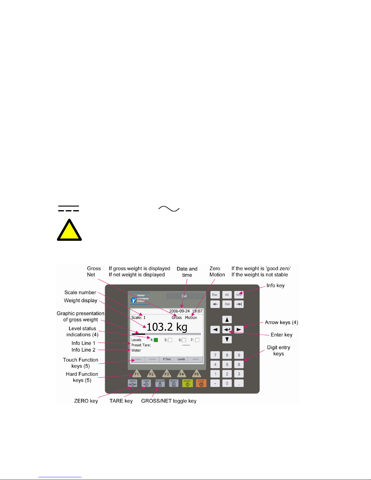
Front panel of instrument G4, types PM, DT, and HE.
2
Page 7
G4 Multi Channel Weighing Instrument
Front panel
General
G4 has a flat, dustproof, and waterproof front panel with a back lighted and touch
sensitive graphic colour LCD display and all necessary keys to perform weighing,
batching, and set-up operations.
Display
G4 normally displays either gross weight or net weight digitally, and in some cases
also gives a graphic representation of the gross weight.
Actual status information for the weight value and date and time will also be shown
at the display.
The Level status (max 4 levels) for the scale and other configurable information may
also be displayed in some cases.
If an error occurs this will be indicated by an error code at the display.
Info key
The Info key at the upper right corner of the panel is used to enter G4 menu system.
Function keys
Just below the display there are five function keys, marked F1 to F5.
Actual key functions, if any, are indicated at the lower line of the display.
To the right of the display, four arrow keys are provided. These keys control
the position of the cursor, the indicated area at the display.
The Enter key (
) is situated between the arrow keys. It is used to accept
the selection indicated by the cursor, to finish the entry of a value etc.
A set of keys for entry of digits is also provided.
Pressing function keys or the Enter key can be replaced by tapping at corresponding
areas in the display.
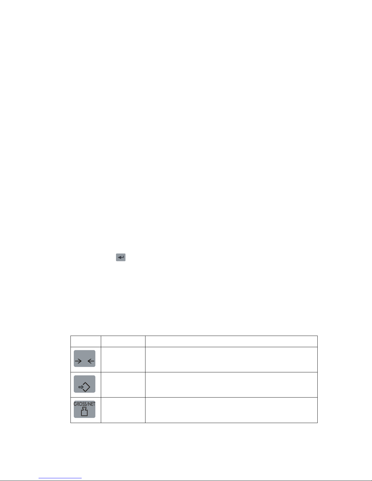
Symbol keys
Six keys, marked with weighing symbols, are provided at the lower border of the panel.
Three of them control the zero setting function, the tare function, and the gross/net
function. The remaining three keys have no function in these instrument versions.
Key Name Function
ZERO
0
ZERO Setting the gross weight value to zero (provided the value
is in the zeroing range: –1 % to +3 % of the capacity) and
setting the auto tare value to zero.
TARE
T
TARE Taring, i.e. entry of the gross weight as auto tare value and
display of net weight zero. Depending on actual setting
taring may be prevented if ‘Motion’ is displayed.
B/N
GROSS/NET Toggling between display of gross weight and net weight.
Net weight can be displayed only if a tare value other than
zero has been entered.
3
Page 8
Operating instructions, Quick installation
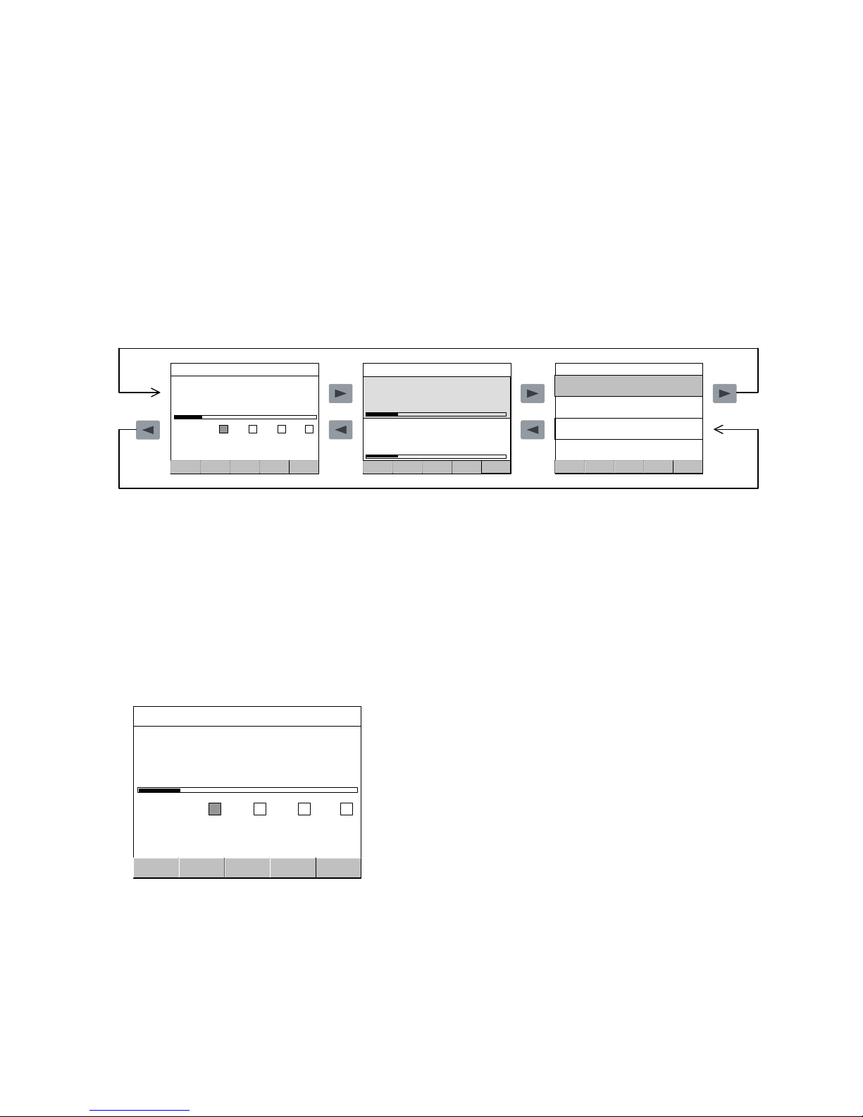
Display alternatives
It is possible to configure G4 to display one, two or four scales at a time, or a
combination of the mentioned views. If a combination of views is used, the arrow keys
'right' and 'left' are used to select a display alternative. Only configured scales will be
shown.
Arrow keys 'up' and 'down' are used to select one of the configured scales. When
several scales are displayed, the selected scale is indicated yellow. The function keys
will influence only the selected scale.
If display of only one scale is selected, detailed information of weight and other selected
information can be presented.
If display of two or four scales is selected, the weight values will be shown, but less other
information.
2006-09-24 19:07
------ ------ ------P.Tare Levels
Scale: 1 Gross
103.2 kg
Levels 4: 5: 6: 7:
Preset Tare: 33.0kg
Water
2006-09-24 19:07
------ ------ ------P.Tare Levels
Scale: 1
Gross
102.8 kg
Scale: 2
Net Zero
000.0 kg
Scale: 3
Net Zero
000.0 kg
Scale: 4
Gross
004.9 kg
2006-09-24 19:07
------ ------ ------P.Tare Levels
Scale: 2
Net Motion
3.4 kg
Scale: 1
Gross
103.2 kg
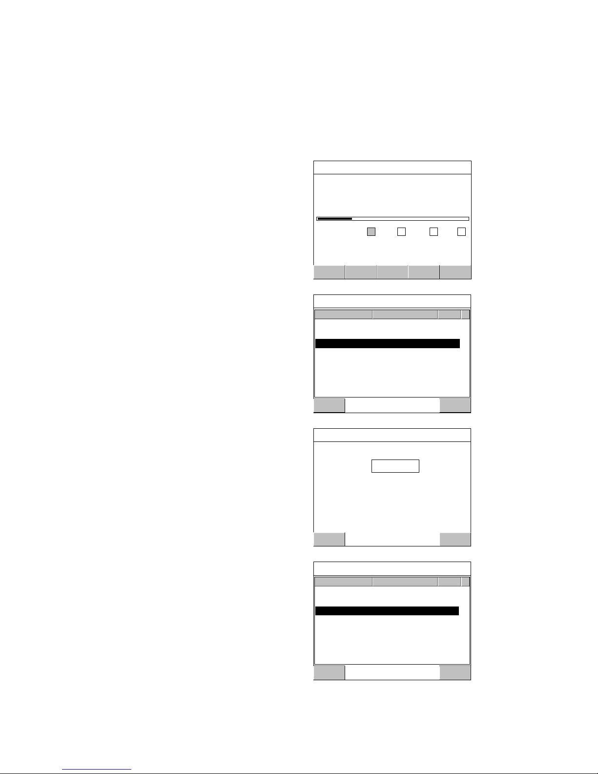
‘Level status’
Status of the level supervision is presented in four boxes below the weight value
presentation. The boxes have fixed positions. When a digit is shown at a box,
the corresponding Level is in use. For each scale the four lowest level numbers
that are in use will be shown. A Level box will be marked green when the level
of the supervised weight signal is above the set value for that Level.
‘Information lines’
By set-up parameters it is possible to configure the instrument to display selected
information on two information lines below the Level status boxes.
2006-09-24 19:07
Scale: 1 Gross
103.2 kg
Levels 4: 5: 6: 7:
Preset Tare: 33.0kg
Water
------ ------ P.Tare Levels ------
Example:
Levels 4, 5, 6, and 7 are in use; the weight signal is above Level 4.
Preset Tare (33.0 kg for Scale 1) on Info line 1.
Scale Name (Water for Scale 1) on Info line 2.
4
Page 9

G4 Multi Channel Weighing Instrument
Operation
Zero indication and zero adjustment
A basic zero setting of the gross weight for unloaded scale is performed at installation
as a part of the calibration. When a ‘good zero’ is displayed, the text ‘Zero’ is shown
to the right in the display.
Minor correction of the zero value may be needed and can rapidly be performed.
Zero adjustment
If, for unloaded scale, the text ‘Zero’ is not shown, but the gross weight is
close to zero, a rapid zero adjustment can be performed.
The gross weight must be stable (text ‘Motion’ not shown) and the key ZERO
must be enabled.
2006-09-24 19:07
Scale: 1 Gross
000.2 kg
Levels 4: 5: 6: 7:
Preset Tare: -----
Water
------ ------ P.Tare Levels ------
ZERO
0
2006-09-24 19:07
Scale: 1 Gross Zero
000.0 kg
Levels 4: 5: 6: 7:
Preset Tare: -----
Water
------ ------ P.Tare Levels ------
Zero adjustment can only be performed if the accumulated deviation from the basic zero
setting in the last calibration is within -1 % to +3 % of the ‘Capacity’.
In other cases a new basic zero setting must be performed.
Gross weight
The gross weight is the total weight loaded on the scale after zero setting.
Gross weight is displayed when the text ‘Gross’ is shown in the display.
When net weight is displayed, the GROSS/NET key can be pressed to change
to display of gross weight, provided that the GROSS/NET key is enabled.
2006-09-24 19:07
Scale: 1 Net
103.2 kg
Levels 4: 5: 6: 7:
Preset Tare: -----
Water
------ ------ P.Tare Levels ------
GROSS/NET
B/N
2006-09-24 19:07
Scale: 1 Gross
143.4 kg
Levels 4: 5: 6: 7 :
Preset Tare: ------
Water
------ ------ P.Tare Levels ------
In some cases, gross weight is shown as a graphic bar at the display.
Maximum length of the bar corresponds to ‘Capacity’ of the scale.
5
Page 10

Operating instructions, Quick installation
Net weight
The net weight is the difference between the gross weight and a tare value.
If the tare value is zero, net weight can not be displayed.
Net weight is displayed when the text ‘Net’ is shown in the display.
When gross weight is displayed, the GROSS/NET key can be pressed to change
to display of net weight, provided that the GROSS/NET key is enabled.
2006-09-24 19:07
Scale: 1 Gross
143.4 kg
Levels 4: 5: 6: 7:
Preset Tare: ------
Water
------ ------ P.Tare Levels ------
GROSS/NET
B/N
2006-09-24 19:07
Scale: 1
Levels
Preset Tare:
Water
Net
103.2 kg
4: 5: 6: 7:
-----
------ ------ P.Tare Lev els ------
Taring
Taring means storing of a tare value for the scale. Net weight will be calculated as
the difference between the gross weight and this tare value. If the tare value is zero,
net weight will not be displayed.
At default setting, taring can always be performed, provided the key TARE is enabled.
But the scale can also be set to allow taring only at stable weight (when the text
‘Motion’ is not shown).
In G4 two tare values can be used: Auto tare and Preset tare.
Auto tare
By taring, the actual gross weight is stored as Auto tare value, and the scale will switch
to display of net weight ‘zero’.
2006-09-24 19:07
Scale: 1 Gross
014.5 kg
Levels 4: 5: 6: 7:
Preset Tare: ------
Water
------ ------ P.Tare Levels ------
TARE
T
2006-09-24 19:07
Scale: 1
Levels
Preset Tare:
Water
Net Zero
000.0 kg
4: 5: 6: 7:
-----
------ ------ P.Tare Lev els ------
6
Page 11

G4 Multi Channel Weighing Instrument
Editing Preset tare
In this example Scale 1 is set for taring with
‘Preset tare’, and for displaying the value
of the ‘Preset Tare’ at Info Line 1
(and Scale Name at Info Line 2).
The example shows editing the Preset tare
value, using the numeric keypad.
Press 'P.Tare'.
2006-09-24 19:07
Scale: 1 Gross
034.5 kg
Levels 4: 5: 6: 7:
Preset Tare: 0.00 kg
Water
------ ------ P.Tare Levels ------
Press 'Edit' to edit the value.
If Operator Lock is activated,
the Operator Code will be needed.
Preset tare, Scale 1
Preset Tare 1 0.0 kg
Edit Escape
The actual value of 'Preset tare' is displayed.
Use the numeric keypad to write the new value.
Finish by 'Enter'.
Edit: Preset tare 1
Enter Escape
Value: kg
Maximum value: 999999 kg
Minimum value: 0 kg
33.0
Menu 'Preset tare, Scale 1' will be shown
with the new value.
Press 'Escape' to return to display of
normal weighing operation.
Preset tare, Scale 1
Preset Tare 1 33.0 kg
Edit Escape
7
Page 12
Operating instructions, Quick installation
Level supervision
With G4 it is possible to supervise different weighing signals at defined levels.
The instrument contains 32 supervising units, Level 1 to Level 32, which can be
connected to the scales by the parameter set-up. For each scale up to 4 connected
Levels are indicated at the display in normal operation. All Levels connected to a scale
are shown if 'Levels' or function key F4 is pressed.
Edit Levels
The supervision levels are easily edited from
the G4 front panel during normal operation.
In this example Scale 1 has five levels of
supervision.
Level number 6 should be edited.
Press 'Levels'.
Select Level 6 by using arrow keys up and
down to position the indicator.
(Or tap at Level 6 to edit.)
Press 'Edit'.
If Operator Lock is activated, the Operator Code
will be needed.
The actual value of Level 6 is displayed.
Use the numeric keypad to write the new value.
Finish by 'Enter'.
Menu 'Levels, Scale 1' will be shown
with the new value for Level 6.
Press Escape' to return to display of
normal weighing operation.
2006-09-24 19:07
------ ------ ------P.Tare Levels
Scale: 1 Gross
034.5 kg
Levels 4: 5: 6: 7:
Preset Tare: 33.0 kg
Water
Levels, Scale 1
Edit Escape
Level 4 20.0 kg
Level 5 40.0 kg
Level 6 55.0 kg
Level 7 85.0 kg
Level 9 120.0 kg
Edit: Level 6
Enter Escape
Value: kg 60.0
Maximum value: 999999 kg
Minimum value: -999999 kg
Levels, Scale 1
Edit Escape
Level 4 20.0 kg
Level 5 40.0 kg
Level 6 60.0 kg
Level 7 85.0 kg
Level 9 120.0 kg
8
Page 13

G4 Multi Channel Weighing Instrument
Flow display
When option Flow display is activated for a scale, function key F5 will show
the text 'W/F'. Pressing function key F5, or tapping at 'W/F', will switch the scale
between display of weight value (indicated by 'Gross' or 'Net') and display of
flow value (indicated by 'Flow').
2006-09-24 19:07
Scale: 1 Gross
123.4 kg
Levels 4: 5: 6: 7:
Preset Tare: 33.0 kg
Water
------ ------ P.Tare Levels W/F
W/F
2006-09-24 19:07
Scale: 1
Levels
Preset Tare:
Water
Flow
0.00 kg/s
4: 5: 6: 7 :
33.0 kg
------ ------ P.Tare Levels W/F
9
Page 14

Operating instructions, Quick installation
10
Page 15

G4 Multi Channel Weighing Instrument
Installation
Mechanical installation
The instrument G4 has a flat plastic front panel and can be ordered with three
different housings: aluminium housing for panel mounting or stand-alone use,
or stainless steel housing for stand-alone use in harsh environment.
Instruments for panel mounting have an integrated gasket that gives sealed
attachment to mounting panels. Stand-alone instruments have sealed housings.
Electrical installation
The field wiring of the instrument shall be suitable to the environment
(e.g. chemically) in the end-user application.
Mains cables shall be separated and routed away from SELV or
!
SELV-E field wiring.
For DT and HE instruments UL Listed and KAM cord type flexible cables shall be used.
For cable diameters, see specification in the Technical Manual.
These instruments have plugged cable entry holes. Replace a suitable number of plugs
by the strain reliefs delivered with the instrument.
Field wiring installation shall comply with any national regulations, hereunder National
Electrical Code (NEC) for US and/or Canadian Electrical Code for Canada.
• A switch or circuit-breaker shall be included in the building installation.
• The switch shall be in close proximity to the equipment and
within easy reach of the operator
• The switch shall be marked as the disconnecting device for the equipment.
• The equipment switch or circuit-breaker employed as disconnecting device shall
comply with relevant requirements of IEC 60947-1 and IEC 60947-3.
The power supply for the instruments can be made via an external dc supply unit
or an internal ac/dc supply unit.
All electrical connections to G4, including connection to ground, are made via
plug-in terminal blocks. Shielded cables are needed, exept for the power input,
and the cables should be routed so that electromagnetic interference from power
cables is avoided.
WARNING
Make sure that that the power to the instrument is turned off before:
- any modules are removed from or inserted in the instrument.
- any connections are connected to or disconnected from the instrument.
All modules should be regarded as ESD sensitive. Make sure that an ESD safe
environment is maintained when inserting modules, removing modules and
when handling modules separately from the instrument. Modules must be kept
in metallised ESD bag when not mounted in the instrument.
11
Page 16
Operating instructions, Quick installation
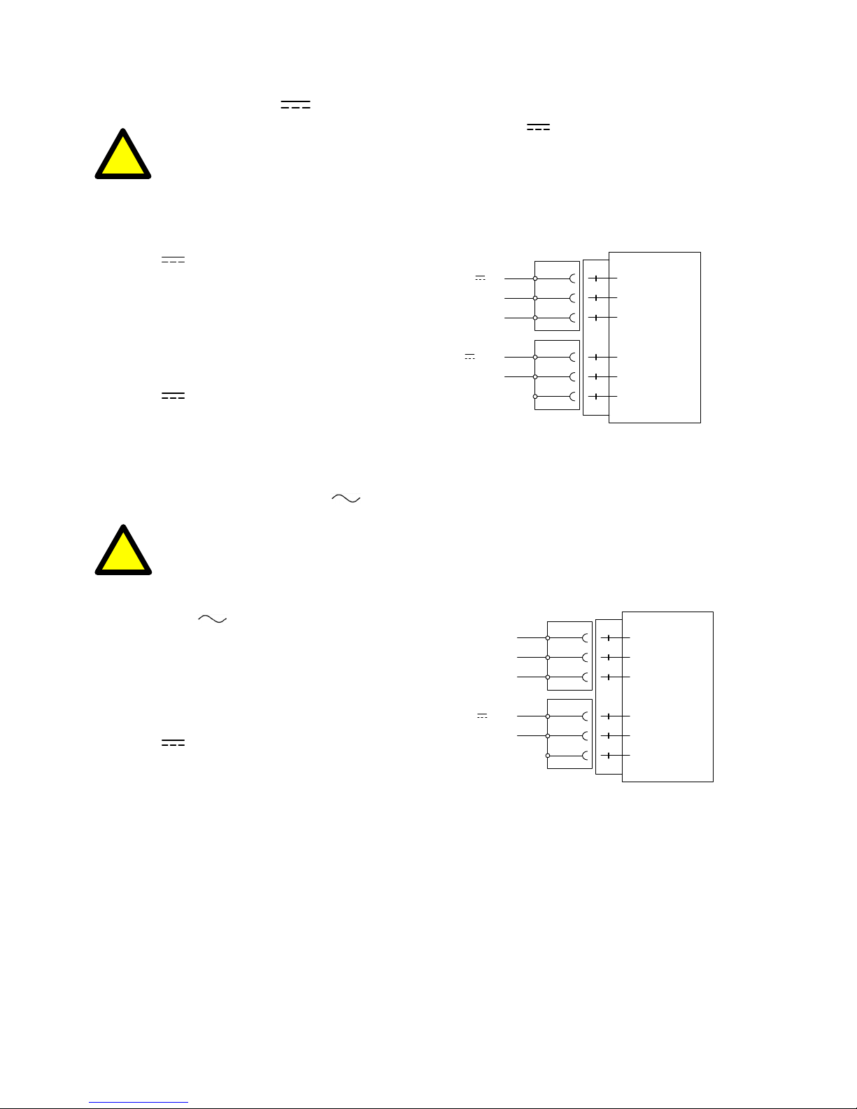
DC SUPPLY 24 V
!
The output of the external dc supply must be rated 24 V , ±15%
including fluctuations, min. 40 W. The supply must provide Double Insulation
between Mains parts and 24 V SELV or SELV-E circuit, and a limited-energy
circuit (max. available current 8 A). For the US market this energy limit
can be achieved with an ANSI/UL 248-14 fuse rated 5 A.
For other markets an IEC 60127 T type fuse rated 4 A may also be used.
24 V In
+24 V In
Terminals 1, 2, and 3.
Connect power to terminal 1 (positive) and
0 V
Ground
terminal 2 (0 V). To achieve functional
grounding, terminal 3 should be connected
to ground.
+24 V Out
0 V
24 V Out
Terminals 4 (positive) and 5 can be used
to supply max. 100 mA to logics, like
outputs and inputs.
AC SUPPLY 110-240 V
!
Mains supply cable shall be separated and routed away
from SELV or SELV-E field wiring.
Remove power before removing the module from the instrument.
Make sure the fixation screws are well tightened during operation.
110-240 V
In
Terminals 1, 2, and 3.
110-240 V~
Connect power to terminal 1 and 2.
Protective earth
To achieve functional grounding, terminal 3
should be connected to protective earth.
+24 V Out
0 V
24 V Out
Terminals 4 (positive) and 5 can be used
to supply max. 100 mA to logics, like
outputs and inputs.
1
DC SUPPLY
0 V
Shield
0 V
Shield
+24 VDC In
+24 VDC Out
2
3
4
5
6
1
AC SUPPLY
Shield
0 V
Shield
110-240 VAC
+24 VDC Out
2
3
4
5
6
12
Page 17

G4 Multi Channel Weighing Instrument
CPU unit
External computing devices connected to the CPU communication interfaces
of the instrument have to comply with the standard, UL 60950.
The internal battery in the CPU module is to be used only in the equipment
where servicing of the battery circuit and replacement of the lithium battery
will be done by a trained technician.
COM1
RS-232 Serial communication.
This is a SELV/SELV-E circuit.
COM 1 can be used for serial communication
(DTE)
RS-9p232
25p
!
with computer/PLC (Modbus RTU).
Point to point communication, only one
G4 unit connected to the computer/PLC.
Connections are made to terminals
7 to 9. Shielded cable must be used.
Connect the shield to terminal 10.
COM2
RS-485 Serial communication for
2-wire or 4-wire with common 0 V.
This is a SELV/SELV-E circuit.
Communication port COM2 can be
used for serial communication with
computer/PLC (Modbus RTU).
Connections are made to terminals
1 to 5. Shielded cable must be used.
Connect the shield to terminal 6.
The communication line must be
terminated at both ends.
If G4 is connected at the end of
the communication line, the switches
T2 and R2 must be set according to
the table below.
2-wire termination:
Both T2 switches ON,
both R2 switches OFF.
4-wire termination:
Both T2 switches ON
both R2 switches ON.
2 3
3 2
5 7
TX
RX
0V
Shield
COM1 RS-232
10
9
8
7
RS485 2-wire
COM2
+5
0
+5
0
T2
+5
T2
0
R2
+5
R2
0
1
T-
T+
R-
R+
0 V
Shield
6
2
3
4
5
T2
T2
R2
R2
RS485 4-wire
COM2
1
T-
T+
R-
R+
0 V
Shield
6
2
3
4
5
13
Page 18

Operating instructions, Quick installation
WF IN, WF IN2 and HS WF2
!
The voltage levels on connectors of I/O modules shall not exceed
hazardous voltage levels of 30 Vrms, 42.4 Vpeak or 60 Vdc under normal
conditions. In wet locations these voltage levels shall not exceed 16 Vrms,
22.6 Vpeak or 35 Vdc.
Transducer inputs
Terminals 17 – 23 (channel 1), 10 – 16 (channel 2). See next page.
Transducer connection should be handled with great care to achieve good
measuring data. Transducer integrated cables may not be shortened.
NOTE!
Transducer cables must be routed at least 200 mm away from 230/380 V, 50/60 Hz
power cables. By cables with other frequencies or high power, an even wider distance
is preferable.
4-wire connection should be used if the transducer integrated cable is long enough to
be connected directly to a transducer input. At 4-wire connection, some terminals must
be interconnected as shown in the figure on next page.
6-wire connection should be used if the integrated cable must be lengthened
or if several transducers should be connected to one transducer input.
The channel 1 cable shield must be connected to terminal 21 and
the channel 2 cable shield must be connected to terminal 14.
In WF IN and WF IN2 the shield terminals are internally connected to the G4 housing,
which is internally connected to earth via the power supply connector terminal 3 (Shield).
The shield shall not be connected at any other point.
In HS WF2 the transducer input channels are separately insulated by operational
insulation and the shields can be connected to the most convenient ground/earth point.
This can be the junction box when using multiple transducers or at the barrier ground
when using Ex zener barriers.
In the junction box SL-4 from Nobel Weighing Systems, see figure, all necessary
terminals are provided.
14
Page 19

G4 Multi Channel Weighing Instrument
10
15
13
12
11
14
16
Exc.-
Exc.+
Sign.+
Sign.-
4-wire connection
Transducer
Transducer input, ch. 2
Exc+
Sense+
Exc-
Sense-
Sign+
Sign-
Shield
Junction box 6-wire connection Transducer input, ch. 1
17
22
20
19
18
21
23
Exc.-
Exc.+
Sign.+
Sign.-
Transducer
Transducer
Exc.-
Exc.+
Sign.+
Sign.-
Exc+
Sense+
Exc-
Sense-
Sign+
Sign-
Shield
A transducer may be connected directly to terminals at the transducer input.
For several transducers or long distances,
a junction box and lengthening cable is needed.
For a HS WF2 channel, the shield can be connected to
ground/earth at any point.
15
Page 20

Operating instructions, Quick installation
16
Page 21

G4 Multi Channel Weighing Instrument
Basic set-up
General
All operating functions in G4 are controlled by parameters, stored in the instrument
memory. The actual setting of the parameter values can be edited during normal
weighing operation, using the touch display and the keys on the front panel.
WARNING. Changes done during editing of set-up parameters will affect the
behaviour of the instrument immediately. The user must take all necessary
precautions to prevent any undesired effects in process monitored or controlled
by the G4 instrument or a connected control system.
It is strongly recommended to activate the set-up lock in the instrument to prevent
any unauthorized changes of set-up parameters.
This section proposes a number of parameters to set, that will rapidly give
the instrument a useful presentation mode and basic measuring properties.
It contains setting of, for example, the measurement unit and resolution for
the weight value, and also some parameter settings for data sheet calibration
and deadweight calibration in two points.
If you are dealing with an already working instrument we recommend that you perform
a backup of the set-up parameters before you make any changes to the instrument.
When the set-up is finished, all parameter values should be noted (see appendix 1
and 2), or backed up in a file. Backup to an USB memory (or internal file) can be done
from menu 'Maintenance', sub menu 'Create Backup'.
Appendix 1 and 2 to this manual contains suitable forms to fill in for the instrument
hardware configuration and for the set-up parameters, covered by this manual.
Hardware configuration
The instruments G4, types PM/DT/HE, have room for one fieldbus module and six
other modules. The configuration of installed modules, used measuring channels,
and scale numbers is made in set-up parameter menu 'Hardware Config.'.
At delivery of an instrument, the hardware configuration normally corresponds to
the set-up. If any mismatch between installed modules and hardware configuration
occurs, an error message will be shown at instrument start-up.
Consult 'G4 Multi Channel Weighing Instrument Technical Manual PM/DT/HE types'
if you need to change the hardware configuration.
Security lock
With an instrument G4 it is possible to perform set-up operations during normal
operation, which may influence for example the performance of a scale. To prevent
these dangers, the instrument is equipped with security locks at two levels that can
be activated to protect from unauthorized access to editing of parameters and values.
Four-digit codes for the locks can be defined by the customer.
By default setting the code for both locks is: 1 9 3 7 .
17
Page 22

Operating instructions, Quick installation
Common parameters
G4 has a number of parameters that are
common for the whole instrument.
They are found in menu 'General',
a sub menu to 'Set-up parameters'.
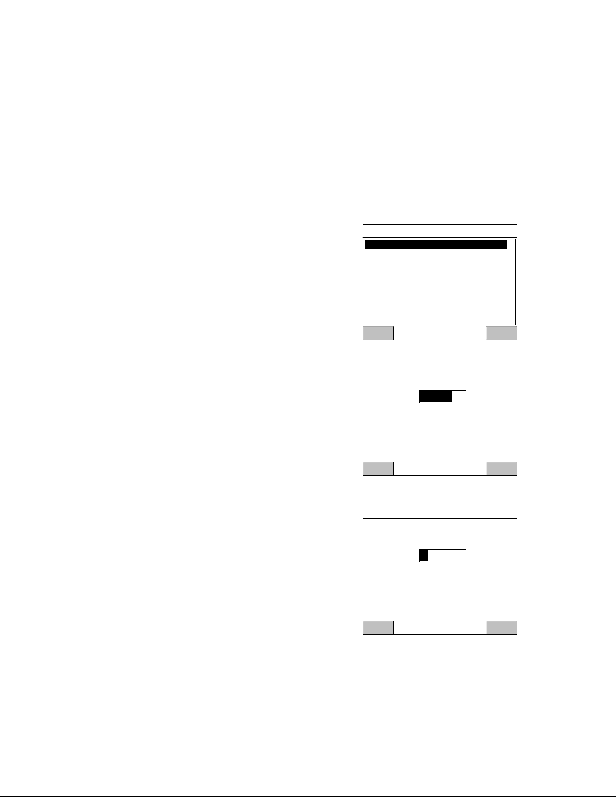
Press the key marked 'Info' at the upper right
corner of the instrument panel.
In the 'Main Menu',
use the arrow keys ‘up’ or 'down' to position
the indicator on line 'Parameter Set-up'.
Press 'Enter' to open 'Parameter Set-up'.
In menu 'Parameter set-up'
position the indicator on line 'General'.
Press 'Enter' to open 'General'.
In menu 'General', position the indicator
on the parameter to edit.
Some basic parameters are explained below.
Press 'Enter' to open the editing menu.
The Set-up Code or the Operator Code
may be needed.
Language
'Language' was selected in menu 'General'.
Use the arrow keys to position the indicator on
the desired language.
The selected language will be used for all
displayed text at the screen, and for all
parameter names.
Finish by 'Enter', and menu 'General'
will appear again.
2006-09-24 19:07
------ ------ ------P.Tare Levels
Scale: 1 Gross
034.5 kg
Levels
Main Menu
Enter Escape
Levels
Setpoints
Clock Set-up
Preset Tare
System Information
Maintenance
Network Configuration
Parameter Set-up
Parameter Set-up
Enter Escape
Hardware Config.
Communication
Level Supervision
Calibration
Setpoints
Inputs
Outputs
General
General
Enter Escape
Instrument Name
Display Mode 1 & 2 & 4 Scales
Info Line 1 Mode Not in use
Start Mode Auto
Info Line 2 Mode Not in use
Date Format YYYY-MM-DD
Time Format 24 h
Language English
Gross/Net key On
Tare key On
Edit: Language
Enter Escape
English
Svenska
18
Page 23

G4 Multi Channel Weighing Instrument
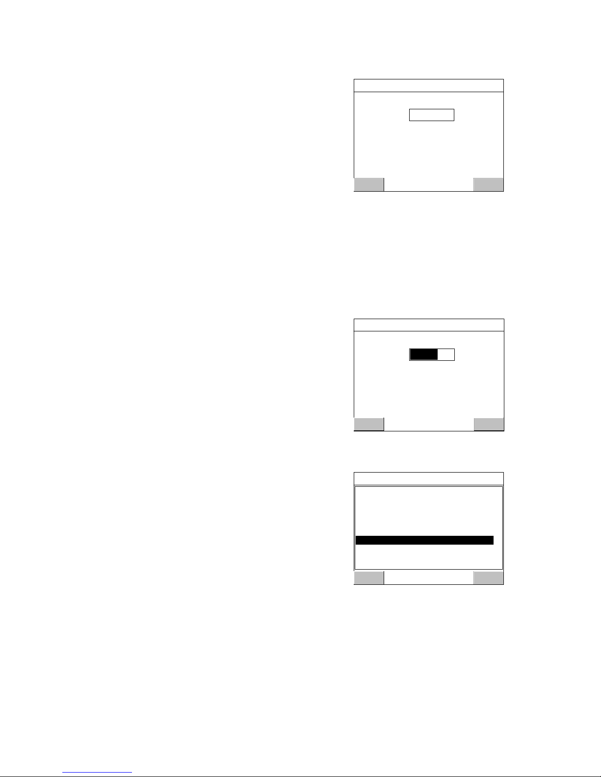
Date Format
'Date Format' was selected in menu 'General'.
Use the arrow keys to position the indicator on
the desired date format.
Y = year, M = month, D = day.
Finish by 'Enter', and menu 'General'
will appear again.
Time Format
'Time Format' was selected in menu 'General'.
Use the arrow keys to position the indicator on
the desired time format.
Finish by 'Enter', and menu 'General'
will appear again.
Set-up Lock
For security reasons, we recommend setting of
this parameter to 'On'.
'Set-up Lock' was selected in menu 'General'.
Use the arrow keys to select 'Off' or 'On' for the
Set-up Lock. If the lock is set to 'On', a 'Set-up
Code' will be needed to perform editing of
set-up parameters, and a parameter for the
'Set-up Code' will be available. See below.
Finish by 'Enter', and menu 'General' will appear
again.
Set-up Code
Edit: Date Format
Enter Escape
YYYY-MM-DD
YYYY-DD-MM
DD-MM-YYYY
DD/MM/YYYY
Edit: Time Format
Enter Escape
12 h
24 h
Edit: Set-up Lock
Enter Escape
Off
On
As the above parameter 'Set-up Lock' was set
to 'On', this parameter appeared in the list
of parameters in menu 'General'.
'Set-up Code' was selected in menu 'General'.
Use the numeric keypad to edit the default
code value '1 9 3 7' to another four-digit value.
Finish by 'Enter', and menu 'General'
will appear again.
Edit: Set-up Code
Enter Escape
Value: 1937
Maximum value: 9999
Minimum value: 1
In menu 'General', press 'Escape' twice to return to the 'Main Menu'.
See next page to perform Clock Set-up for the instrument.
19
Page 24

-
Operating instructions, Quick installation
Clock set-up
Date/time information is always presented at the G4 weight display.
Setting of correct date and time is performed in ‘Clock Set-up’,
a sub menu to the 'Main Menu'.
Setting of date and time doesn't interrupt normal weighing operation.
(To open 'Main Menu' from normal weight display, press the key marked 'Info'
at the upper right corner of the instrument front panel.)
In the 'Main Menu', use arrow keys 'up' or 'down'
to position the indicator on line 'Clock Set-up'.
Press 'Enter' to open 'Clock Set-up'.
Main Menu
Levels
Setpoints
Preset Tare
Clock Set up
Parameter Set-up
System Information
Maintenance
Network Configuration
Enter Escape
A flashing cursor line appears at 'Year'.
Use arrow keys to edit the value in the
selected field.
Use the Tab-key ( ) to move it from field
to field.
Clock Set-up
OK Cancel
Year: 2006
Month: 9
Day: 24
Time: 19 07 23
Apply
Press 'OK' to accept the new values and return to the 'Main Menu'.
Press 'Apply' to accept the new values and stay in the 'Clock Set-up' menu.
Press 'Cancel' to reject the new settings and return to the 'Main Menu'.
20
Page 25

-
G4 Multi Channel Weighing Instrument
Scale calibration
All calibration set-up parameters are set individually for each scale. The scale number
is used to distinguish similar parameters in different scales. The following example
shows a set-up sequence for Scale 1, so all parameter names will begin with 1: .
Individual parameters for the scales are found in menu 'Calibration',
a sub menu to 'Parameter Set-up'.
('Parameter Set-up' is a sub menu to the 'Main Menu'. To open 'Main Menu'
from normal weight display, press the key marked 'Info' at the upper right corner
of the instrument front panel.)
In the 'Main Menu', use the arrow keys
‘up’ or 'down' to position the indicator
on line 'Parameter Set-up'.
Press 'Enter'.
In menu 'Parameter Set-up', use the arrow keys
to position the indicator on line 'Calibration'.
Press 'Enter' to open 'Calibration'.
Main Menu
Levels
Setpoints
Clock Set-up
Preset Tare
System Information
Maintenance
Network Configuration
Parameter Set up
Enter Escape
Parameter Set-up
General
Hardware Config.
Communication
Level Supervision
Setpoints
Inputs
Outputs
Calibration
Enter Escape
Menu 'Calibration' displays the scales
that are in use.
Use arrow keys to position the indicator
on the desired Scale number,
in this example Scale 1.
Press 'Enter' to open 'Scale 1'.
Calibration
Scale 1
Scale 2
Enter Escape
21
Page 26

Operating instructions, Quick installation
In menu 'Scale 1', arrow keys can be used to scroll
the list of parameters, and to select a parameter name
by positioning the indicator on the corresponding line.
Some basic parameters are explained below.
Press 'Enter' to edit the value of a selected parameter.
The Operator Code or the Set-up Code
may be needed to continue.
Scale 1
1:Measurement Unit
1:Capacity
1:WFIN Update Rate
1:Resolution
1:Filter Window
1:Motion Detect Window
1:No Motion Delay
1:Scale Name
1:Motion Check
1:Overload Check
kg
500.0 kg
37 Hz
0.1
1.00 kg
0.10 kg
1.0 s
Off
Off
Enter Escape
1:Measurement Unit
Edit: 1:Measurement Unit
This parameter defines the measurement unit that
will be used for the measured value and for related
set-up parameters.
Use the arrow keys to position the indicator
on the desired unit.
Press 'Enter' to accept.
Menu 'Scale 1' will appear again.
NONE
g
kg
t
lb
oz
N
daN
kN
psi
Enter
Current Gross Weight:
111.36
(0.42971 mV/V)
Escape
1:Resolution
Edit: Resolution
This parameter defines the smallest change in
measured value that will be shown,
and the decimal point position for the scale.
0.1 means the scale will display 0.0 – 0.1 – 0.2 – 0.3 etc.
0.2 means the scale will display 0.0 – 0.2 – 0.4 – 0.6 etc.
0.5 means the scale will display 0.0 – 0.5 – 1.0 – 1.5 etc.
Use the arrow keys to position the indicator
on the desired resolution.
0.001
0.002
0.005
0.01
0.02
0.05
0.2
0.1
0.5
1
Enter
Current Gross Weight:
Press 'Enter' to accept.
111.36
(0.42971 mV/V)
Escape
Menu 'Scale 1' will appear again.
1:Capacity
This parameter defines the nominal range for the scale.
The value of ‘Capacity’ is shown with measurement unit
and decimal point position according to the settings
above.
Use the numerical keypad to write the desired value
of capacity for the scale.
Press 'Enter' to accept.
Menu 'Scale 1' will appear again.
Edit: 1:Capacity
Enter Escape
Value: kg500.0
Maximum value: 999999 kg
Minimum value: 0.5 kg
22
Page 27

G4 Multi Channel Weighing Instrument
The last line in menu 'Scale 1' gives access
to menu 'Scale 1 Calibration', where calibration
type can be selected.
Use the arrow keys to position the indicator on
line 'Scale 1 Calibration'.
Press 'Enter'.
Menu 'Scale 1 Calibration' shows the current
type of calibration for scale 1, and the parameter
values of that calibration.
To perform a new calibration, use arrow keys to
position the indicator on line '1:Calibration Type'
Press 'Enter'.
Scale 1
1:Zero Tracking Off
1:Tare Corr. Mode Auto
1:WFIN Update Rate 37 Hz
1:Flow Calculation Off
1:Filter Window 1.00 kg
1:Motion Detect Window 0.10 kg
1:No Motion Delay 1.0 s
1:Motion Check Off
1:Overload Check Off
Scale 1 Calibration
Enter
Current Gross Weight:
(0.42971 mV/V)
111.36
Escape
Scale 1 Calibration
1:Rated Output 3 2.03900 mV/V
1:Set Zero 0.00 kg
1:Zero Offset 0.00 kg
1:Conversion Factor 9.80665
1:Number of Transducers 3
1:Rated Load 2000.00
1:Rated Output 1 2.03900 mV/V
1:Rated Output 2 2.03900 mV/V
1:Calibration Type Data Sheet
Enter
Current Gross Weight:
(0.42971 mV/V)
111.36
Escape
1:Calibration Type
This parameter defines the type of calibration
to perform for the scale.
Three calibration types are available.
'Data Sheet' calibration for fast calibration
when transducer data is available and
the installation is free from mechanical
disturbances.
'Deadweight' calibration, the most accurate
calibration type, where known weights are
used to give well defined load on the scale.
'Table' calibration for entry of recorded values
from a previous calibration.
Use arrow keys to indicate the desired
type of calibration.
Press 'Enter'.
Edit: 1:Calibration Type
Data Sheet
Deadweight
Table
Enter
Current Gross Weight:
(0.42971 mV/V)
111.36
Escape
A question will be displayed.
To start the calibration, tap at 'Yes'.
Do you want to start a new calibration?
(Current calibration will be lost)
Yes No
!
Performing a data sheet calibration is described on pages 24 - 26.
Performing a deadweight calibration is described on pages 27 - 29.
23
Page 28
Operating instructions, Quick installation
Data sheet calibration
This calibration method can be used when data sheets for the transducers are
available and no external forces influence the weighing installation.
If fixed supports are included, the load must be evenly distributed on all supports.
Data sheet calibration can be performed without any transducers connected,
but the transducers must be connected as the zero setting is performed.
A data sheet calibration for a scale should start with the scale parameters,
described on page 22.
This example shows a Data Sheet calibration for Scale 1.
When data sheet calibration has been selected
and you have accepted to start a new calibration,
menu 'Scale 1 Calibration' will be displayed again.
Use arrow keys 'up' and 'down' to select a parameter
to edit, then press 'Enter' to accept.
All parameters are explained below.
Scale 1 Calibration
1:Rated Output 3 2.03900 mV/V
1:Set Zero 0.00 kg
1:Zero Offset 0.00 kg
1:Conversion Factor 9.80665
1:Number of Transducers 3
1:Rated Load 2000.00
1:Rated Output 1 2.03900 mV/V
1:Rated Output 2 2.03900 mV/V
1:Calibration Type Data Sheet
Enter
Current Gross Weight:
(0.42971 mV/V)
111.36
Escape
1:Conversion Factor
This parameter defines the relationship between a
weight value expressed in transducer data sheet unit
and the same weight value expressed in measurement
unit. The default value, 9.80665, can be used when
transducers in N (Newton) are used for weighing in kg.
Use the numeric keypad to write a new value for
'1:Conversion Factor'.
Press 'Enter' to accept.
Edit: 1:Conversion Factor
Enter Escape
Value: 9.80665
Maximum value: 100
Minimum value: 0.01
Current Gross Weight:
(0.42971 mV/V)
111.36
Menu 'Scale 1 Calibration' will appear again.
1:Number of Transducers
This parameter value should be set to the number of
support points for the load, including all transducers
and fixed support points. The number will affect
the number of lines '1:Rated Output'.
Use the numeric keypad to write a new value for
'1:Number of Transducers’.
Press 'Enter' to accept.
Menu 'Scale 1 Calibration' will appear again.
Edit: 1:Number of Transducers
Enter Escape
Value: 3
Maximum value: 4
Minimum value: 1
Current Gross Weight:
(0.42971 mV/V)
111.36
24
Page 29

G4 Multi Channel Weighing Instrument
1:Rated Load
Rated load for the transducer is a value, given in
the data sheet. All the transducers in the scale
must have the same impedance and rated load.
The rated load value, expressed in the unit of the
data sheet, should be entered for this parameter.
Use the numeric keypad to write
a new value for '1:Rated Load’.
Press 'Enter' to accept.
Menu 'Scale 1 Calibration' will appear again.
1:Rated Output 1, 2, etc
The number of lines '1:Rated Output …'
corresponds to '1:Number of Transducers' above.
These parameter values should be set to
the output signal values for the transducers,
given in the data sheets.
For a fixed support point the value of the rated
output should be set to 0.00000 mV/V.
Use the numeric keypad to write
a new value for '1:Rated Output 1’.
Edit: 1:Rated Load
Enter Escape
Value: 2000.00
Maximum value: 999999
Minimum value: 1
Current Gross Weight:
(0.42971 mV/V)
111.36
Edit: 1:Rated Output 1
Enter Escape
Value: mV/V 2.03900
Maximum value: 9.99999 mV/V
Minimum value: 0 mV/V
Current Gross Weight:
(0.42971 mV/V)
111.36
Press 'Enter' to accept.
Menu 'Scale 1 Calibration' will appear again and the rated output value for all
transducers and fixed support points can be entered in the same way.
1:Set Zero
This parameter is used to make the scale display
gross weight zero when it is unloaded. Make sure
the scale is completely unloaded before this setting
is performed.
The current gross weight is indicated in the display.
The value '0.00 kg' is proposed for '1:Set Zero'.
Press 'Enter' to accept 0.00 kg.
Edit: 1:Set Zero
Enter Escape
Value: kg0.00
Maximum value: 999999 kg
Minimum value: -999999 kg
Current Gross Weight:
(0.42971 mV/V)
111.36
Menu 'Scale 1 Calibration' will be displayed with
the 'Current gross weight' changed to the new
value of '1:Set Zero' ('zero' in this example).
The value of '1:Zero Offset' has changed
correspondingly.
1:Zero Offset
This parameter shows the offset value needed
to make the scale display the gross weight 'zero'
for unloaded scale.
The value of '1:Zero Offset' should not be edited.
Scale 1 Calibration
1:Rated Output 3 2.03900 mV/V
1:Calibration Type Data Sheet
1:Zero Offset 111.36 kg
1:Conversion Factor 9.80665
1:Number of Transducers 3
1:Rated Load 2000.00
1:Rated Output 1 2.03900 mV/V
1:Rated Output 2 2.03900 mV/V
1:Set Zero 0.00 kg
Enter
Current Gross Weight:
(0.42971 mV/V)
000.00
Escape
25
Page 30

Operating instructions, Quick installation
Exit calibration
To exit from calibration, press 'Escape' twice.
A question will be displayed.
Answer Yes to keep the new settings in
the instrument memory,
answer No to exit calibration without saving
(all changes will be rejected).
In both cases the instrument switches
to sub menu 'Calibration'.
Answer Cancel to continue the calibration for Scale 1.
Now it is possible to perform calibration of any remaining scales,
or to return to normal weight display by pressing 'Escape' several times.
Exit calibration
X
Calibration parameter(s) changed!
Do you want to keep the new settings?
No Cancel Yes
?
26
Page 31

G4 Multi Channel Weighing Instrument
Deadweight calibration
This is the most accurate calibration method. It requires that known weights
to at least two-thirds of the scale capacity are available.
A deadweight calibration of a scale should start with the scale parameters,
described on page 22.
An asterisk ( * ) will be shown at the calibration parameters that have not yet
been stored.
This example shows a two-point Deadweight calibration for Scale 1.
When deadweight calibration has been selected
and you have accepted to start a new calibration,
menu 'Scale 1 Calibration' will be displayed again.
Use arrow keys 'up' or 'down' to select a parameter
to edit, then press 'Enter' to accept.
All parameters are explained below.
Scale 1 Calibration
1:Set Zero 0.00 kg
1:Zero Offset 0.00 kg
1:No of Calibration points 2
1:Value Cal. P1* 0.0 kg
1:Value Cal. P2* 500.0 kg
1:Transd. Signal P1 0.00000 mV/V
1:Transd. Signal P2 1.66631 mV/V
1:Calibration Type Deadweight
Enter
Current Gross Weight:
(0.42971 mV/V)
111.36
Escape
1:No of Calibration Points
This parameter defines the number of calibration
points. Up to six points can be selected, parameters
for load value and transducer signal will be
displayed for the selected number of points.
In this example a two-point calibration is described.
Use the numeric keypad to write '2'
for '1:No of Calibration Points’.
Press 'Enter' to accept.
Edit: 1:No of Calibration points
Enter Escape
Value: 2
Maximum value: 6
Minimum value: 2
Current Gross Weight:
(0.42971 mV/V)
111.36
Menu 'Scale 1 Calibration' will appear again.
1:Value Cal. P1
This parameter defines the load for the lowest
calibration point. Normally the scale should be
unloaded and the parameter value set to 0 (zero).
This weight value and the corresponding transducer
signal value are automatically stored for the scale.
The current gross weight is indicated at the bottom
line in the display.
If necessary, use the numeric keypad to write
a new value for '1:Value Cal. P1'.
Press 'Enter' to accept.
Menu 'Scale 1 Calibration' will appear again.
Edit: 1:Value Cal. P1*
Enter Escape
Value: kg 0.0
Maximum value: 999999 kg
Minimum value: -999999 kg
Current Gross Weight:
(0.42971 mV/V)
111.36
27
Page 32
Operating instructions, Quick installation
1:Value Cal. P2
This parameter, in a two point calibration, defines
the load for the highest calibration point. Normally
the scale should be loaded to at least two-thirds
of the scale capacity.
This weight value and the corresponding transducer
signal value are automatically stored for the scale.
The current gross weight is indicated at the bottom
line in the display.
Use the numeric keypad to write the actual
load on the scale for '1:Value Cal. P2'.
Press 'Enter' to accept.
Menu 'Scale 1 Calibration' will appear again.
1:Transd. Signal P1 and 1:Transd. Signal P2
These parameters are only shown and cannot be
edited.
1:Set Zero
This parameter is used to make the scale display
gross weight zero when it is unloaded. Make sure
the scale is completely unloaded before this setting
is performed.
The current gross weight is indicated in the display.
The value '0.00 kg' is proposed for '1:Set Zero'.
Press 'Enter' to accept 0.00 kg.
Menu 'Scale 1 Calibration' will be displayed with
the 'Current gross weight' changed to the new
value of '1:Set Zero'.
The value of '1:Zero Offset' has changed
correspondingly.
1:Zero Offset
This parameter shows the offset value needed
to make the scale display the gross weight 'zero'
for unloaded scale.
The value of '1:Zero Offset' should not be edited.
Edit: 1:Value Cal. P2*
Enter Escape
Value: kg 100.0
Maximum value: 999999 kg
Minimum value: -999999 kg
Current Gross Weight:
(0.67298 mV/V)
098.29
Edit: 1:Set Zero
Enter Escape
Value: kg0.00
Maximum value: 999999 kg
Minimum value: -999999 kg
Current Gross Weight:
(0.42965 mV/V)
-000.38
Scale 1 Calibration
1:Zero Offset -0.38 kg
1:No of Calibration points 2
1:Value Cal. P1 0.0 kg
1:Value Cal. P2 500.0 kg
1:Transd. Signal P1 0.42971 mV/V
1:Transd. Signal P2 0.67298 mV/V
1:Calibration Type Deadweight
1:Set Zero 0.00 kg
Enter
Current Gross Weight:
(0.42965 mV/V)
000.00
Escape
28
Page 33

G4 Multi Channel Weighing Instrument
Exit calibration
To exit from calibration, press 'Escape' twice.
A question will be displayed.
Answer Yes to keep the new settings
in the instrument memory,
answer No to exit calibration without saving
(all changes will be rejected).
In both cases the instrument switches
to sub menu 'Calibration'.
Answer Cancel to continue the calibration for Scale 1.
Now it is possible to perform calibration of any remaining scales,
or to return to normal weight display by pressing 'Escape' several times.
Exit calibration
X
Calibration parameter(s) changed!
Do you want to keep the new settings?
No Cancel Yes
?
29
Page 34

Operating instructions, Quick installation
Zeroing of gross weight
When the scale installation is calibrated, a zeroing is performed in order to get
the gross weight zero when the scale is unloaded. If mechanical equipment is added
later, this will affect the weight display for the scale, and a new zeroing of the gross
weight becomes necessary.
NOTE! The scale must be unloaded when zeroing is performed.
Access ‘Set Zero' for any calibration type.
Navigate to menu 'Calibration' and select
the desired scale, in this example 'Scale 1'.
The sequence is described on page 21.
In menu 'Scale 1', use arrow key 'down'
to position the indicator at the bottom line:
'Scale 1 Calibration'.
Press 'Enter'.
Scale 1
1:Zero Tracking Off
1:Tare Corr. Mode Auto
1:WFIN Update Rate 37 Hz
1:Flow Calculation Off
1:Filter Window 1.00 kg
1:Motion Detect Window 0.10 kg
1:No Motion Delay 1.0 s
1:Motion Check Off
1:Overload Check Off
Scale 1 Calibration
Enter
Current Gross Weight:
(0.42971 mV/V)
111.36
Escape
In menu 'Scale 1 Calibration', use arrow key 'down'
to position the indicator at line '1:Set Zero'.
Press 'Enter'.
The Set-up Code or the Operator Code
may be needed.
Scale 1 Calibration
1:Zero Offset 0.00 kg
1:Calibration Type Deadweight
1:No of Calibration points 2
1:Value Cal. P1 0.0 kg
1:Value Cal. P2 500.0 kg
1:Transd. Signal P1 0.38793 mV/V
1:Transd. Signal P2 1.66631 mV/V
1:Set Zero 0.00 kg
Enter
Current Gross Weight:
(0.42971 mV/V)
111.36
Escape
Menu 'Edit: 1:Set Zero' is displayed,
and the current gross weight is indicated
on the bottom line in the screen.
The value '0.00 kg' is proposed for '1:Set Zero'.
Press 'Enter' to accept 0.00 kg.
Edit: 1:Set Zero
Enter Escape
Value: kg0.00
Maximum value: 999999 kg
Minimum value: -999999 kg
Current Gross Weight:
(0.42971 mV/V)
111.36
Menu 'Scale 1 Calibration' will be displayed with
the 'Current gross weight' changed to the new
value of '1:Set Zero'.
The value of '1:Zero Offset' has changed
correspondingly.
Press 'Escape' to exit from calibration, like described
for 'Deadweight' calibration on page 29.
Scale 1 Calibration
1:Zero Offset 111.36 kg
1:Calibration Type Deadweight
1:No of Calibration points 2
1:Value Cal. P1 0.0 kg
1:Value Cal. P2 500.0 kg
1:Transd. Signal P1 0.38793 mV/V
1:Transd. Signal P2 1.66631 mV/V
1:Set Zero 0.00 kg
Enter
Current Gross Weight:
(0.42971 mV/V)
000.00
Escape
30
Page 35

G4 Multi Channel Weighing Instrument
Common set-up values
Note: Only the set-up parameters covered in this manual are listed.
Location/Notes: .........................................................................................................
Software version: ............................................ Serial number: ...............................
Date: ...................................................
Hardware position Module Serial no. Notes
Slot 1 ......................... ........................... ...........................
Slot 2 ......................... ........................... ...........................
Slot 3 ......................... ........................... ...........................
Slot 4 ......................... ........................... ...........................
Slot 5 ......................... ........................... ...........................
Slot 6 ......................... ........................... ...........................
Fieldbus module ......................... ........................... ...........................
(at the CPU-unit)
Parameter name Default value Set-up value
Language English ...........................
Date Format YYYY-MM-DD ...........................
Time Format 24 h ...........................
Set-up Lock Off ...........................
Set-up Code 1 9 3 7 ...........................
Appendix 1
Common set-up values
Page 36

Operating instructions, Quick installation
Page 37

G4 Multi Channel Weighing Instrument
Scale set-up values
Note: Only the set-up parameters covered in this manual are listed.
Locations/Notes: ............................................................................................................
........................................................................................................................................
Module: .................................... Ser. no.: ......................... Slot no.: ...........................
Channel number: .......................... ...........................
Scale number: .......................... ...........................
Parameter name: Default values
X:Measurement Unit kg ........................... ...........................
X:Resolution 0.1 ........................... ...........................
X:Capacity 500.0 ........................... ...........................
X:Calibration Type Data sheet ........................... ...........................
X:Conversion Factor 9.80665 ........................... ...........................
X:Number of Transd. 3 ........................... ...........................
X:Rated Load 2000.0 ........................... ...........................
X:Rated Output 1 2.03900 ........................... ...........................
X:Rated Output 2 2.03900 ........................... ...........................
X:Rated Output 3 2.03900 ........................... ...........................
X:Rated Output 4 2.03900 ........................... ...........................
X:No of Calibration Points 2 ........................... ...........................
X:Value Cal. P1 0.0 ........................... ...........................
X:Value Cal. P2 500.0 ........................... ...........................
X:Transd. Signal P1 0.00000 ........................... ...........................
X:Transd. Signal P2 1.66631 ........................... ...........................
X:Zero Offset 0.00 ........................... ...........................
Appendix 2
Scale set-up values
Page 38

Operating instructions, Quick installation
Page 39

Page 40

Document no. 35196
Article no. 600 856 R1c
© Vishay Nobel AB, 2011-06-15
Subject to changes without notice.
Vishay Nobel AB BLH
Box 423, SE-691 27 Karlskoga, Sweden 3 Edgewater Drive, Norwood, MA 02726, USA
Phone +46 586 63000 · Fax +46 586 63099 Phone
: 781-298-2200 Fax: 781-762-3988
pw.se@vishaypg.com pw.us@vishaypg.com
www. weighingsolutions.com www.weighingsolutions.com
 Loading...