

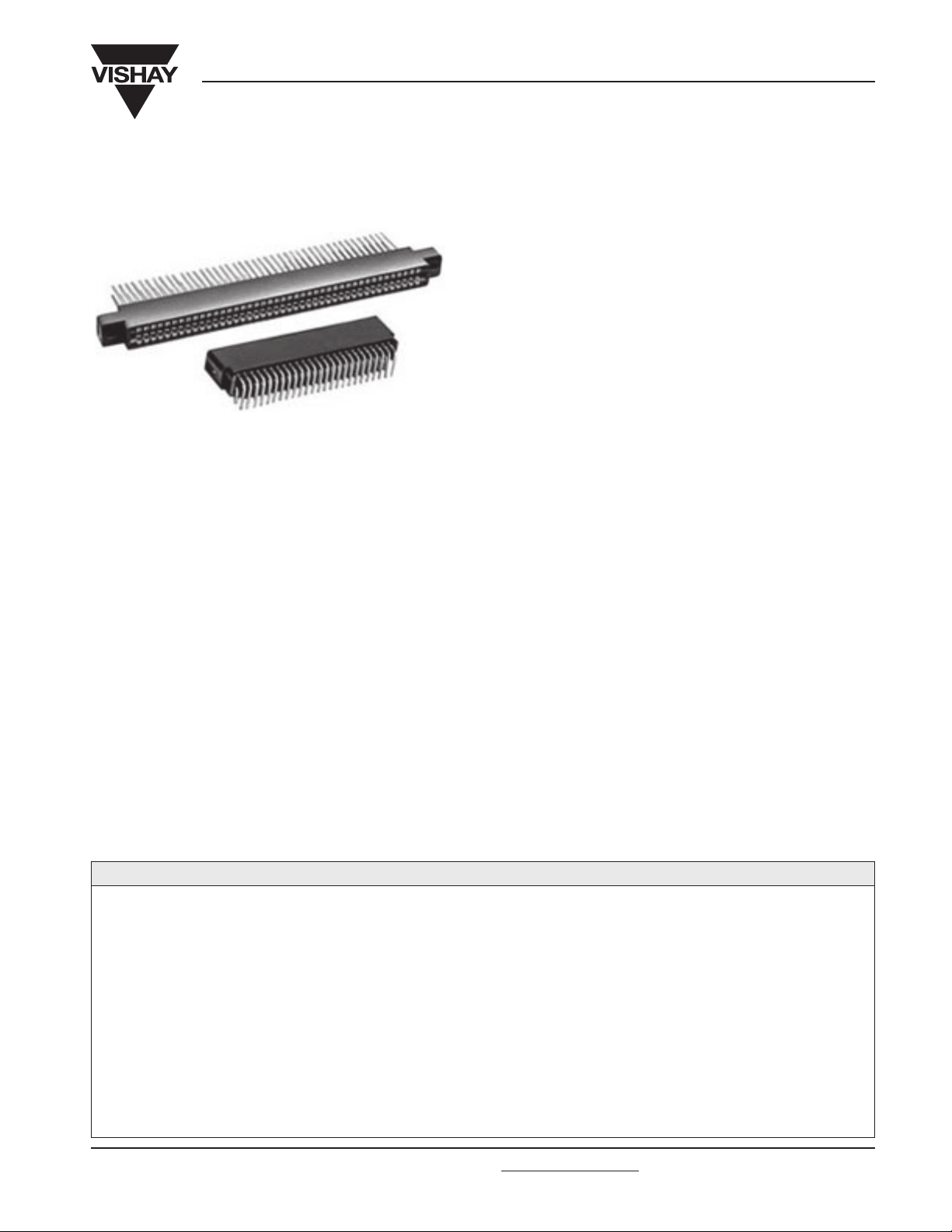
Edgeboard Connectors, Dual Readout, 0.125" [3.17mm] C-C,
Standard and Right Angle Terminals
FEATURES
• Grid Patterns: 0.125" C-C x 0.150" [3.17mm x 3.81mm],
0.125" C-C x 0.200" [3.17mm x 5.08mm] and
0.125" C-C x 0.250" [3.17mm x 6.35mm].
• Standard and right angle terminals.
• Greater design latitude:
3 body materials: Diallyl phthalate, phenolic, glass-filled
polyester and glass-filled polyphenylene sulfied.
7 contact termination styles: 3 standard, 4 right angle.
19 body sizes and 6 mounting styles.
• Selective gold plating.
• Accepts PC board thickness of 0.054" to 0.071" [1.37mm
to 1.80mm].
• Polarization between contact positions in all sizes.
Between contact polarization permits polarizing without loss
ELECTRICAL SPECIFICATIONS
Current Rating: 3 amps.
Test Voltage Between Contacts:
At sea level: 1500VRMS.
At 70,000 feet [21,336 meters]: 325VRMS.
Insulation Resistance: 5000 Megohm minimum at 500VDC
potential.
Contact Resistance: 30 millivolts maximum at rated current
(with gold plating).
Operating Temperature: - 65°C to + 125°C.
Humidity: 96 hours at 90% relative humidity at + 40°C, dried
at room temperature for 3 hours minimum, insulation
resistance was greater than 5000 Megohm.
Durability: After 500 cycles of insertion and withdrawal of a
0.070" [1.78mm] thick steel test board, contact resistance less
than 0.030V at 3 amps on gold plated contacts and individual
contact pair separation force when measured with a 0.054"
[1.37mm] thick steel test blade was greater than 1/2 ounce.
Shock: Three 50g shocks in each of 3 mutually perpendicular
planes with no loss of continuity.
Vibration: 2 hours in each of 3 mutually perpendicular planes,
frequency sweep 10 to 55cps at 0.06 double amplitude with
no loss of continuity.
of contact position.
• Recognized under the Component Program of
Underwriters Laboratories, Inc. Listed under File
E65524, Project 77CH3889.
APPLICATIONS
For use with 0.0625" [1.59mm] printed circuit boards requiring
an edgeboard type connector on 0.125" [3.17mm] centers.
MATERIAL SPECIFICATIONS
Body Material:
“1” glass-filled diallyl phthalate per MIL-M-14, Type SDG-F
green, flame retardant (UL 94V-0).
“2” glass-filled phenolic per MIL-M-14, Type MFH dark green,
flame retardant (UL 94V-0).
“3” thermoplastic polyester, glass-filled, black, flame retardant
(UL 94V-0).
“5” thermoplastic polyphenylene sulfied, glass-filled, brown,
flame retardant (UL 94V-0).
Contacts: Phosphor bronze. (Ordering Information.)
Polarizing Key: Glass reinforced nylon, flame retardant
(UL94H-B).
Plating: Gold. (Ordering Information.)
EB6
Vishay Dale
ORDERING INFORMATION
EB6
MODEL3BODY MATERIAL
1 = Diallyl
Phthalate
2 = Phenolic
3 = Glass-filled
Polyester
5 = Glass-filled
Polyphenylene
Sulfied
Document Number 36002
Revision 14-Aug-02
STANDARD
TERMINAL
VARIATIONS
K
C, D, K,
1R, 2R,
3R, 4R
For technical questions, contact Connectors@vishay.com
40
CONTACTS
6, 10, 12,
14, 15, 18,
22, 24, 25,
28, 30, 31,
32, 35, 36,
40, 43, 44,
49 and 50
per side.
CONTACT PLATING
SG = Selective Gold Plating
(0.00003" [0.000762mm] minimum
thick) on contact area with Gold
Flash on terminal.
SGF = Selective Gold Plating
(0.000010" [0.000254mm] minimum
thick) on contact area with Gold
Flash on terminal.
All Gold Plating over 0.00005"
[0.00127mm] minimum Nickel
Underplate.
Contact factory for additional
plating options.
SG
X
MOUNTING
VARIATIONS
15
POLARIZING
KEY POSITIONS
Key(s) are located to
right of position(s)
designated. Use oddnumbered contact for
ordering: -1, -3, -5, etc.
Required only when
polarizing keys are to
be factory installed.
NOTE: To order
polarizing keys
individually, specify
Model PK-6.
www.vishay.com
5
EB6
Vishay Dale
Edgeboard Connectors, Dual Readout, 0.125" [3.17mm] C-C,
Standard and Right Angle Terminals
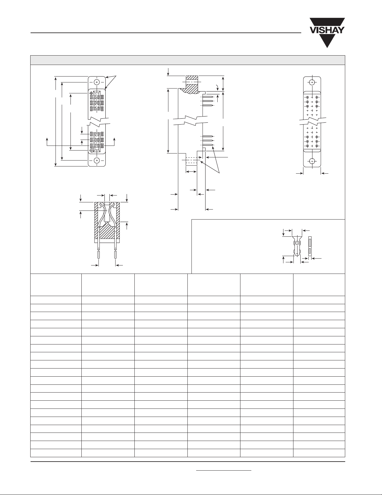
DIMENSIONS in inches [millimeters]
0.060
[1.52]
R Typ.
A
B
C
0.125
[3.17]
Typ.
JJ
Section J-J
0.054 - 0.071 [1.37 - 1.80]
Card Thickness
0.125 [3.17]
Point of
Contact
0.250
[6.35]
0.300 [7.62]
Depth of
Insertion
0.260
[6.60]
D
0.060
[1.52]
Typ.
E
See table for
0.250
[6.35]
Typ.
0.430
[10.92]
Typ.
0.610 [15.49]
Typ.
contact and
mounting variations
0.180
[4.57]
Typ.
Polarizing Key:
When ordering polarizing
keys individually, specify
by the Model Number:
PK-6 between contacts.
Hand insertion tool, TPK-6,
provided upon request.
0.340
[8.64]
Typ.
0.060
[1.52]
Typ.
0.150 [3.81]
0.295
[7.49]
0.096
± 0.002 [2.44 ± 0.050]
0.365
[9.27]
0.031
[0.787]
# OF CONTACT
POSITIONS
PER SIDE A B C D E
6 1.555 [39.50] 1.295 [32.89] 0.875 [22.22] 1.035 [26.29] 0.875 [22.22]
10 2.055 [52.20] 1.795 [45.59] 1.375 [34.92] 1.535 [38.99] 1.375 [34.92]
12 2.305 [58.55] 2.045 [51.94] 1.625 [41.28] 1.785 [45.34] 1.625 [41.28]
14 2.555 [64.90] 2.295 [58.29] 1.875 [47.62] 2.035 [51.69] 1.875 [47.62]
15 2.680 [68.07] 2.420 [61.47] 2.000 [50.80] 2.160 [54.86] 2.000 [50.80]
18 3.055 [77.60] 2.795 [70.99] 2.375 [60.32] 2.535 [64.39] 2.375 [60.32]
22 3.555 [90.30] 3.295 [83.69] 2.875 [73.02] 3.035 [77.09] 2.875 [73.02]
24 3.805 [96.65] 3.545 [90.04] 3.125 [79.38] 3.285 [83.44] 3.125 [79.38]
25 3.930 [99.82] 3.670 [93.22] 3.250 [82.55] 3.410 [86.61] 3.250 [82.55]
28 4.305 [109.35] 4.045 [102.74] 3.625 [92.08] 3.785 [96.14] 3.625 [92.08]
30 4.555 [115.70] 4.295 [109.09] 3.875 [98.42] 4.035 [102.49] 3.875 [98.42]
31 4.680 [118.87] 4.420 [112.27] 4.000 [101.60] 4.160 [105.66] 4.000 [101.60]
32 4.805 [122.05] 4.545 [115.44] 4.125 [104.78] 4.285 [108.84] 4.125 [104.78]
35 5.180 [131.57] 4.920 [124.97] 4.500 [114.30] 4.660 [118.36] 4.500 [114.30]
36 5.305 [134.75] 5.045 [128.14] 4.625 [117.48] 4.785 [121.54] 4.625 [117.48]
40 5.805 [147.45] 5.545 [140.84] 5.125 [130.18] 5.285 [134.24] 5.125 [130.18]
43 6.180 [156.97] 5.920 [150.37] 5.500 [139.70] 5.660 [143.76] 5.500 [139.70]
44 6.305 [160.15] 6.045 [153.54] 5.625 [142.88] 5.785 [146.94] 5.625 [142.88]
49 6.930 [176.02] 6.670 [169.42] 6.250 [158.75] 6.410 [162.81] 6.250 [158.75]
50 7.055 [179.20] 6.795 [172.59] 6.375 [161.92] 6.535 [165.99] 6.375 [161.92]
www.vishay.com
6
For technical questions, contact Connectors@vishay.com
Document Number 36002
Revision 14-Aug-02

EB6
Edgeboard Connectors, Dual Readout, 0.125" [3.17mm] C-C,
Standard and Right Angle Terminals
PHYSICAL SPECIFICATIONS
Contact Type: Bifurcated Cantilever Beam.
Number of Contacts: 6, 10, 12, 14, 15, 18, 22, 24, 25, 28,
30, 31, 32, 35, 36, 40, 43, 44, 49 and 50 per side.
Contact Terminal Variation: Standard terminals.
Type “C” - Dip Solder, 0.025" [0.635mm] square terminals,
0.175" [4.44mm] nominal terminal length below standoffs.
Type “D” - Dip Solder, 0.025" [0.635mm] square terminals,
0.115" [2.92mm] nominal terminal length below standoffs.
Type “K” - Wire Wrap™, 0.025" [0.635mm] square terminals,
0.570" [14.48mm] nominal terminal length below standoffs.
Contact Terminal Variation: Right angle terminals.
Type “1R” - Dip Solder, 0.025" [0.635mm] square terminals,
0.120" [3.05mm] nominal terminal length x 0.150" [3.81mm]
nominal terminal row spacing.
Type “2R” - Dip Solder, 0.025" [0.635mm] square terminals,
0.120" [3.05mm] nominal terminal length x 0.200" [5.08mm]
nominal terminal row spacing.
MOUNTING VARIATIONS in inches [millimeters]
Type “X”
Clearance Hole
Raised Mounting Flange
0.060 [1.52] Ref.
Type “XF”
Clearance Hole
Flush Mounting Flange
0.060 [1.52] Ref.
Vishay Dale
Type “3R” - Dip Solder, 0.025" [0.635mm] square terminals,
0.180" [4.57mm] nominal terminal length x 0.150" [3.81mm]
nominal terminal row spacing.
Type “4R” - Dip Solder, 0.025" [0.635mm] square terminals,
0.180" [4.57mm] nominal terminal length x 0.200" [5.08mm]
nominal terminal row spacing.
Contact Spacing: 0.125" [3.17mm] center to center.
Contact Terminal Row Spacing:
Standard - 0.250" [6.35mm] nominal.
Right Angle - 0.200" [5.08mm] nominal and 0.150" [3.81mm]
nominal.
Card Thickness: 0.054" to 0.071" [1.37mm to 1.80mm].
Card Slot Depth: 0.300" [7.62mm].
Connector Polarization: Between contact polarization key(s)
are located to the right of the contact position(s) designated.
NOTE: High temperature burn-in, edgeboard connectors, with
0.125" [3.17mm] center to center are on page 20 of this catalog.
Type “XS”
Right Angle
Mounting Flange
0.060 [1.52] Ref.
Type “XFS”
Right Angle
Mounting Flange
0.060 [1.52] Ref.
0.125
[3.17]
Dia.
0.430
[10.92]
0.610
[15.49]
Ref.
0.250
[6.35]
0.125
[3.17]
Dia.
0.610
[15.49]
Ref.
0.250
[6.35]
Type “Y”
Threaded Insert
Raised Mounting Flange
0.060 [1.52] Ref.
4-40
UNC-2B
0.430
[10.92]
0.610 [15.49]
Ref.
0.250
[6.35]
Threaded Insert
Flush Mounting Flange
4-40
UNC-2B
TERMINAL VARIATIONS in inches [millimeters]
Type “C” and “D”
Solder Dip, Standard
0.025 [0.635] Square Terminals
0.250
[6.35]
To Fit
0.050
± 0.002
[1.27
± 0.051]
Dia. Eyelet
“C” = 0.175 [4.44]
“D” = 0.115 [2.92]
0.025 [0.635] Square Terminals
Type “K”
Wire Wrap™, Standard
0.250 [6.35]
0.570
[14.48]
[10.92]
Type “YF”
0.060 [1.52] Ref.
0.610
[15.49]
Ref.
Type “1R”, “2R”, “3R” and “4R”
0.025 [0.635] Square Terminals
0.125
[3.17]
Dia.
0.125
[3.17]
0.430
0.610 [15.49]
0.250
[6.35]
Right Angle
Ref.
B
0.590
[14.99]
A
0.250
[6.35]
No Mounting Flange
0.205 [5.21]
TYPE A B
Ø 0.125
[3.17]
0.125 [3.17]
0.610
[15.49]
Ref.
0.250 [6.35]
Type “W”
0.060 [1.52] Ref.
0.430
0.610
[15.49]
Ref.
[10.92]
1R 0.150 0.120 ± 0.030
[3.81] [3.05 ± 0.762]
2R 0.200 0.120 ± 0.030
[5.08] [3.05 ± .762]
3R 0.150 0.180 ± 0.030
[3.81] [4.57 ± 0.762]
4R 0.200 0.180 ± 0.030
[5.08] [4.57 ± 0.762]
Document Number 36002
Revision 14-Aug-02
For technical questions, contact Connectors@vishay.com
www.vishay.com
7

Legal Disclaimer Notice
Vishay
Disclaimer
All product specifications and data are subject to change without notice.
Vishay Intertechnology, Inc., its affiliates, agents, and employees, and all persons acting on its or their behalf
(collectively, “Vishay”), disclaim any and all liability for any errors, inaccuracies or incompleteness contained herein
or in any other disclosure relating to any product.
Vishay disclaims any and all liability arising out of the use or application of any product described herein or of any
information provided herein to the maximum extent permitted by law. The product specifications do not expand or
otherwise modify Vishay’s terms and conditions of purchase, including but not limited to the warranty expressed
therein, which apply to these products.
No license, express or implied, by estoppel or otherwise, to any intellectual property rights is granted by this
document or by any conduct of Vishay.
The products shown herein are not designed for use in medical, life-saving, or life-sustaining applications unless
otherwise expressly indicated. Customers using or selling Vishay products not expressly indicated for use in such
applications do so entirely at their own risk and agree to fully indemnify Vishay for any damages arising or resulting
from such use or sale. Please contact authorized Vishay personnel to obtain written terms and conditions regarding
products designed for such applications.
Product names and markings noted herein may be trademarks of their respective owners.
Document Number: 91000 www.vishay.com
Revision: 18-Jul-08 1
 Loading...