

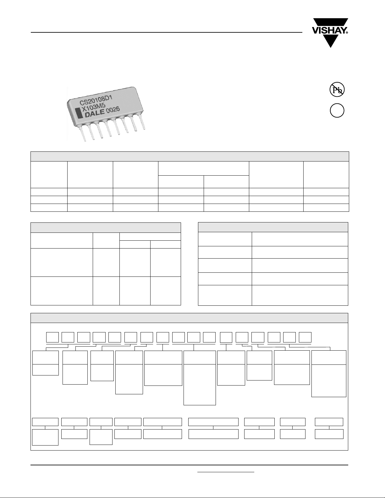
CS201
Vishay Dale
Capacitor Networks, Single-In-Line,
Conformal Coated SIP “D” Profile
FEATURES
• X7R and COG capacitors available
• Multiple isolated capacitors
• Multiple capacitors, common ground
• Custom design capability
• Lead (Pb)-free version is RoHS compliant
• “D” 0.300" [7.62 mm] package height (maximum)
STANDARD ELECTRICAL SPECIFICATIONS
VISHAY
DALE
MODEL
CS201 D 1 33 pF - 3900 pF 470 pF - 0.1 µF ± 10 (K), ± 20 (M) 50 (5)
CS201 D 3 33 pF - 3900 pF 470 pF - 0.1 µF ± 10 (K), ± 20 (M) 50 (5)
CS201 D 4 33 pF - 3900 pF 470 pF - 0.1 µF ± 10 (K), ± 20 (M) 50 (5)
* COG capacitors may be substituted for X7R capacitors
PROFILE SCHEMATIC CAPACITANCE
RANGE
COG* X7R
CAPACITANCE
TOLERANCE
(- 55 °C to + 125 °C)
%
CAPACITOR
VOLTAGE
at 85 °C
Available
e1
RoHS*
COMPLIANT
VDC
TECHNICAL SPECIFICATIONS
PARAMETER UNIT
Temperature Coefficient
(- 55 °C to +125 °C)
Dissipation Factor
(maximum)
ppm/°C
or
%
± % 0.15 2.5
COG X7R
± 30
ppm/°C
CS201
± 15 %
MECHANICAL SPECIFICATIONS
Marking Resistance
to Solvents:
Solderability: Per MIL-STD-202, Method 208E
Body:
Terminals: Phosphorus-bronze, solder plated
Marking:
Permanency testing per MIL-STD202, Method 215
High alumina, epoxy coated
(Flammability UL94 V-0)
Pin #1 identifier, DALE or D, Part
number (abbreviated as space
allows), Date code
GLOBAL PART NUMBER INFORMATION
New Global Part Numbering: 20108D1C103K5P (preferred part numbering format)
20108D1C103K5P___P
GLOBAL
MODEL
201
= CS20104 = 4 Pin
Historical Part Number example: CS20108D1C103K5 (will continue to be accepted)
CS201
PIN
COUNT
08
= 8 Pin
18
= 18 Pin
08 D
PA CK A G E
HEIGHT
D
= “D”
Profile
SCHEMATIC CHARACTERISTIC
1
3
4
= Special
0
1C
C
= COG
X
= X7R
S
= Special
CAPACITANCE
(in picofarads) 2
digit significant
figure, followed
by a multiplier
392
VAL UE
330
= 3900 pF
104
= 0.1 µF
= 33 pF
TOLERANCE VOLTAGE PACKAGING SPECIAL
K
103
= ± 10 %
M
= ± 20 %
S
= Special
5
= 50V
S
= Special
E
= Lead (Pb)-free
Bulk
P
= Tin/Lead, Bulk
K5 P03
,
Blank = Standard
(Dash Number)
(up to 3 digits)
1-999
From
applicable
as
HISTORICAL
MODEL
* Pb containing terminations are not RoHS compliant, exemptions may apply
www.vishay.com For technical questions, contact: ff2aresistors@vishay.com
1 Revision: 09-Jan-07
PIN COUNT PACKAGE
HEIGHT
SCHEMATIC CHARACTERISTIC CAPACITANCE VALUE TOLERANCE VOLTAGE PACKAGING
Document Number: 31522
CS201
Capacitor Networks, Single-In-Line,
Conformal Coated SIP, “D” Profile
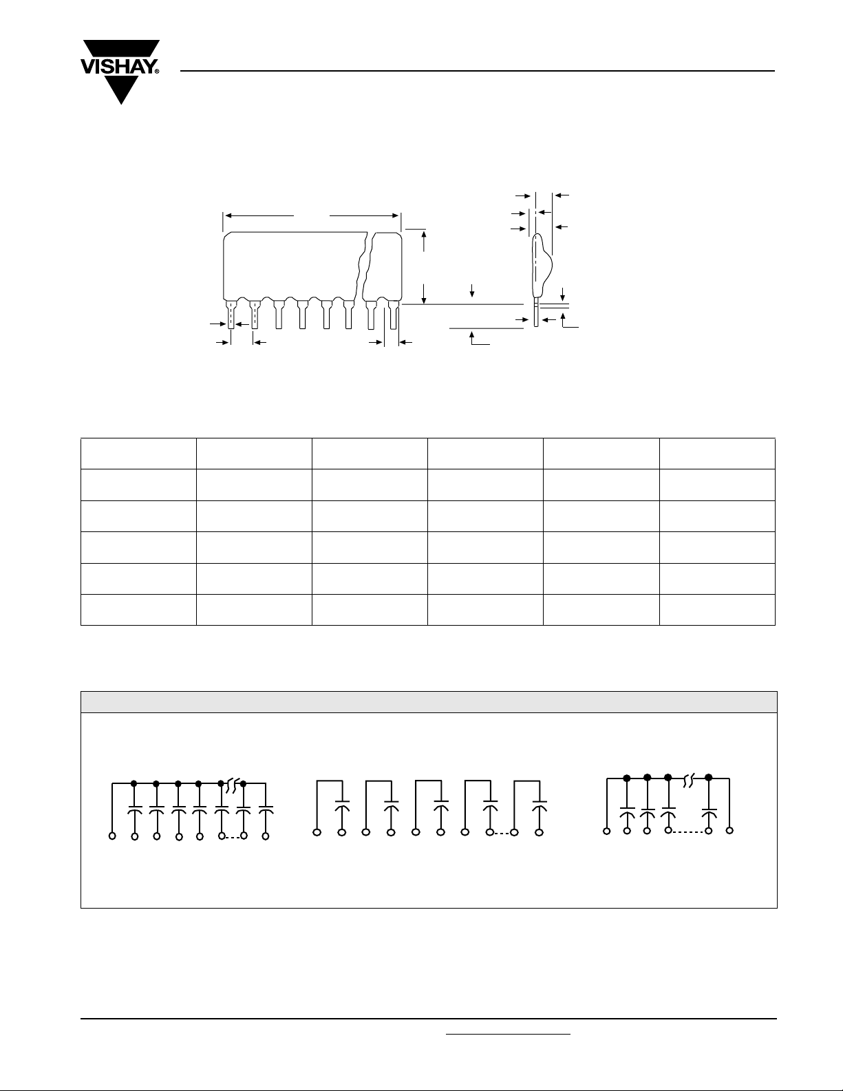
DIMENSIONS in inches [millimeters]
L
Max.
0.020
[0.508]
0.100 ± 0.005 [2.54 ± 0.127]
Non-Cumulative
at Point of Egress
Pin #1 is extreme left-hand terminal on side with marking.
NUMBER
OF PINS
L
MAXIMUM
NUMBER
OF PINS
0.050 [1.27]
0.300
[7.62]
0.050 [1.27]
Typ .
0.010
[0.254]
0.135 + 0.015 - 0.010
[3.43 + 0.381 - 0.254]
L
MAXIMUM
0.085 [2.160]
Typ.
0.135 [3.43]
Max.
Seating Plane
for 0.040 [1.016] Ø Hole
0
.007 [0.178] Ref.
NUMBER
OF PINS
Vishay Dale
L
MAXIMUM
4 pin 0.400 [10.16] 9 pin 0.900 [22.86] 14 pin 1.400 [35.56]
5 pin 0.500 [12.70] 10 pin 1.000 [25.40] 15 pin 1.500 [38.10]
6 pin 0.600 [15.24] 11 pin 1.100 [27.94] 16 pin 1.600 [40.64]
7 pin 0.700 [17.78] 12 pin 1.200 [30.48] 17 pin 1.700 [43.18]
8 pin 0.800 [20.32] 13 pin 1.300 [33.02] 18 pin 1.800 [45.72]
SCHEMATICS
Schematic 1
1 2 3 4 5 6 n-1 n
Common Bus - 1 Ground Lead
Schematic 3
1 2 3 4 5 6 7 8 n-1 n
Isolated Capacitor Sections
Schematic 4
1 2 3 4 n-1 n
Common Bus - 2 Ground Leads
Document Number: 31522 For technical questions, contact: ff2aresistors@vishay.com
Revision: 09-Jan-07 2
www.vishay.com

Legal Disclaimer Notice
Vishay
Notice
Specifications of the products displayed herein are subject to change without notice. Vishay Intertechnology, Inc.,
or anyone on its behalf, assumes no responsibility or liability for any errors or inaccuracies.
Information contained herein is intended to provide a product description only. No license, express or implied, by
estoppel or otherwise, to any intellectual property rights is granted by this document. Except as provided in Vishay's
terms and conditions of sale for such products, Vishay assumes no liability whatsoever, and disclaims any express
or implied warranty, relating to sale and/or use of Vishay products including liability or warranties relating to fitness
for a particular purpose, merchantability, or infringement of any patent, copyright, or other intellectual property right.
The products shown herein are not designed for use in medical, life-saving, or life-sustaining applications.
Customers using or selling these products for use in such applications do so at their own risk and agree to fully
indemnify Vishay for any damages resulting from such improper use or sale.
Document Number: 91000 www.vishay.com
Revision: 08-Apr-05 1
 Loading...