

Page 1
CMA 0204
Vishay Beyschlag
High Pulse Load MELF Resistor
CMA 0204 speciality MELF resistors with advanced pulse
load capability are the perfect choice for the protection of
circuitry with signal or mains input lines from surge pulses.
The resistors are also suitable for circuits exposed to high
levels of electromagnetic interference or electrostatic
discharge. The applications are in all fields of automotive,
telecommunication, industrial and medical equipment.
FEATURES
• Special carbon film technology
• Up to 4 kV single pulse capability
• Up to 70 W continuous pulse load
• ESD capability: 6 kV, Human Body Model
• Compatible with lead (Pb)-free and lead containing
soldering processes
• Lead (Pb)-free and RoHS compliant
APPLICATIONS
• Automotive
• Telecommunication
• Industrial
• Medical equipment
METRIC SIZES
DIN: 0204
CECC: RC 3715M
TECHNICAL SPECIFICATIONS
DESCRIPTION CMA 0204
Metric CECC size RC 3715M
Resistance range 10 Ω to 100 kΩ
Resistance tolerance ± 2 %
Temperature coefficient see TCR graph
Operation mode standard power
Climatic category (LCT/UCT/days) 55/125/56 55/155/56
Rated dissipation, P
Operating voltage, U
Film temperature
Max. resistance change at P
|ΔR/R| after: 1000 h
Permissible voltage against ambient (insulation):
Failure rate ≤ 1 × 10
Note: These resistors do not feature a limited lifetime when operated within the permissible limits. However, resistance value drift increasing over
operating time may result in exceeding a limit acceptable to the specific application, thereby establishing a functional lifetime.
1)
The power dissipation on the resistor generates a temperature rise against the local ambient, depending on the heatflow support of the
printed-circuit board (thermal resistance). The rated dissipation applies only if the permitted film temperature is not exceeded. Furthermore, a
high level of ambient temperature or of power dissipation may raise the temperature of the solder joint, hence special solder alloys or board
materials may be required to maintain the reliability of the assembly.
2)
Film temperatures above the specified range may be permissible, e.g. 175 °C. Please contact the factory for details.
1)
70
AC/DC 200 V
max
2)
for resistance range, 10 Ω to 100 kΩ
70
8000 h ≤ 2 % ≤ 4 %
1 minute; U
continuous 75 V
ins
0.25 W 0.4 W
125 °C 155 °C
≤ 1 % ≤ 2 %
300 V
-9
/h
www.vishay.com For technical questions contact: ff3bresistors@vishay.com Document Number: 28717
58 Revision: 18-Jul-06
Page 2
CMA 0204
High Pulse Load MELF Resistor
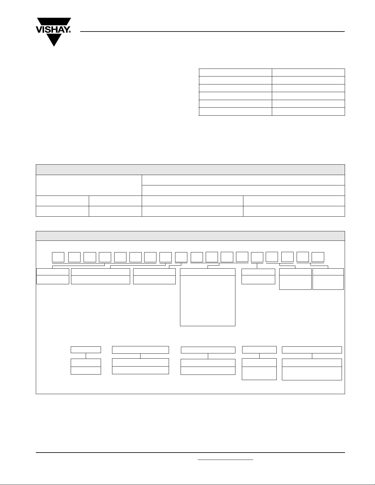
12NC INFORMATION
• The resistors have a 12-digit numeric code starting with
2312.
• The subsequent 4 digits indicate the resistor type,
specification and packaging; see the 12NC table.
• The remaining 4 digits indicate the resistance value:
– The first 3 digits indicate the resistance value.
– The last digit indicates the resistance decade in
accordance with the 12NC Indicating Resistance
Decade table.
12NC - resistor type and packaging
DESCRIPTION
TYPE TOL.
CMA 0204 ± 2 % 159 2.... 149 2....
Last Digit of 12NC Indicating Resistance Decade
RESISTANCE DECADE LAST DIGIT
10 Ω to 99.9 Ω 9
100 Ω to 999 Ω 1
1 kΩ to 9.99 kΩ 2
10 kΩ to 99.9 kΩ 3
100 kΩ to 999 kΩ 4
12NC Example
The 12NC of a CMA 0204 resistor, value 47 kΩ with ± 2 %
tolerance, supplied in blister tape of 3000 units per reel is:
2312 159 24703.
ORDERING CODE 2312 ... .....
BLISTER TAPE ON REEL
BL B0
Vishay Beyschlag
PART NUMBER AND PRODUCT DESCRIPTION
PART NUMBER2): CMA02040X4701GB300
1)
CMA02040X4701GB300
MODEL/SIZE SPECIAL CHARACTER TC VALUE TOLERANCE
CMA0204 0 = neutral X = no indication 3 digit value
1 digit multiplier
Multiplier
-1
9 = *10
0
0 = *10
1
1 = *10
2
2 = *10
3
3 = *10
PRODUCT DESCRIPTION4): CMA 0204 2 % BL 4K7
CMA 0204 2 % BL 4K7
MODEL SIZE TOLERANCE PACKAGING
CMA 0204 ± 2 % BL
Notes
1. Products can be ordered using either the PRODUCT DESCRIPTION or the 12NC.
2. The PART NUMBER is shown to facilitate the introduction of the unified part numbering system. Currently, this PART NUMBER is applicable
in the Americas and in Asia/Pacific only.
3. Please refer to table PACKAGING, see below.
4. For CMA0204 the temperature coefficient is not identified in the PRODUCT DESCRIPTION.
G = ± 2 % B3
B0
PA C KA G I N G3)SPECIAL
up to 2 digits
B0
3)
RESISTANCE VALUE
00
100R = 100 Ω
4K7 = 4.7 kΩ
= standard
Document Number: 28717 For technical questions contact: ff3bresistors@vishay.com
Revision: 18-Jul-06 59
www.vishay.com
Page 3
CMA 0204
Vishay Beyschlag
PACKAGING
MODEL
CMA0204
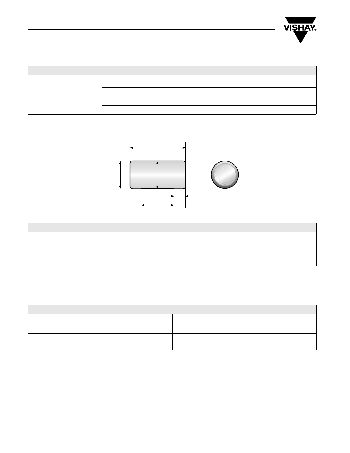
DIMENSIONS
High Pulse Load MELF Resistor
BLISTER TAPE ON REEL
ACC. IEC 60286-3
DIAMETER PIECES/REEL
180 mm/7” 3000 B3 = BL
330 mm/13” 10 000 B0
L
Color code marking
D
D
1
L
1
1)
K
CODE
DIMENSIONS - MELF resistor types, mass and relevant physical dimensions
TYPE
CMA 0204 3.6 + 0/- 0.2 1.4 + 0/- 0.1 1.8 D + 0/- 0.15 0.8 ± 0.1 19
Color code marking is applied according to IEC 60062* in four bands (E24 series). Each color band appears as a single solid line, voids are
permissible if at least 1/3 of the band is visible from each radial angle of view. The last color band for tolerance is approx, 50 % wider than the
other bands. An interrupted band between the 2nd and 3rd full band identifies the special carbon film type.
L
(mm)
D
(mm)
L
1 min
(mm)
D
1
(mm)
K
(mm)
MASS
(mg)
TOLERANCE AND RESISTANCE RANGE
1)
TOLERANCE
± 2 % 10 Ω to 100 kΩ
1)
Resistance value to be selected from E24 series.
RESISTANCE VALUE
CMA 0204
www.vishay.com For technical questions contact: ff3bresistors@vishay.com Document Number: 28717
60 Revision: 18-Jul-06
Page 4

CMA 0204
High Pulse Load MELF Resistor
DESCRIPTION
Production of the CMA 0204 speciality MELF resistors with
advanced pulse load capability is strictly controlled and
follows an extensive set of instructions established for
reproducibility. A homogeneous and dense carbon film is
deposited on a high grade ceramic body (85 % Al
plated steel termination caps are firmly pressed on the
coated rods. A special laser is used to achieve the target
value by smoothly cutting a helical groove in the resistive
layer without damaging the ceramics. The resistors are
covered by protective coating designed for electrical,
mechanical and climatic protection.The terminations receive
a final pure tin on nickel plating. Four color code rings
designate the resistance value and tolerance in accordance
with IEC 60 062*.
The result of the determined production is verified by an
extensive testing procedure performed on 100 % of the
individual resistors. Only accepted products are laid directly
into the blister tape in accordance with IEC 60 286-3*.
2O3
). Nickel
Vishay Beyschlag
APPROVALS
Where applicable the resistors are tested in accordance with
EN 140401-803 (superseding CECC 40401-803) which
refers to EN 60115-1, EN 140400 and the variety of
enviromental text procedures of the IEC 60068* series.
Vishay BEYSCHLAG has achieved "Approval of
Manufacturer" in accordance with IEC QC 001002-3,
clause 2. The release certificate for “Technology Approval
Schedule” in accordance with CECC 240001 based on
IEC QC 001002-3, clause 6 is granted for the Vishay
BEYSCHLAG manufacturing process.
Note:
* The quoted IEC standards are also released as EN standards with
the same number and identical contents.
ASSEMBLY
The resistors are suitable for processing on automatic
SMD assembly systems. They are suitable for automatic
soldering using wave, reflow or vapour phase as shown in
IEC 61760-1*. Excellent solderability is proven, even after
extended storage in excess of 10 years. The encapsulation
is resistant to all cleaning solvents commonly used in the
electronics industry, including alcohols, esters and aqueous
solutions. The resistors are completely lead (Pb)-free, the
pure tin plating provides compatibility with lead (Pb)-free
soldering processes. The immunity of the plating against tin
whisker growth has been proven under extensive testing.
1)
All products comply with the GADSL
EECA-EICTA
2)
list of legal restrictions on hazardous
substances. This includes full compliance with the following
directives:
2000/53/EC End of Vehicle life Directive (ELV) and Annex II
•
(ELV II)
• 2002/95/EC Restriction of the use of Hazardous
Substances Directive (RoHS)
• 2002/96/EC Waste Electrical and Electronic Equipment
Directive (WEEE)
and the CEFIC-
1)
Global Automotive Declarable Substance List, see www.gadsl.org
2)
CEFIC (European Chemical Industry Council), EECA (European
Electronic Component Manufacturers Association), EICTA
(European trade organisation representing the information and
communications technology and consumer electronics), see
www.eicta.org
chemicals for electronics
Document Number: 28717 For technical questions contact: ff3bresistors@vishay.com
Revision: 18-Jul-06 61
-> issues -> environment policy -> chemicals ->
www.vishay.com
Page 5

CMA 0204
Vishay Beyschlag
FUNCTIONAL PERFORMANCE
P
1
W
0.5
Power Dissipation
0
- 50 0 50
Derating - Standard Operation
P
1
High Pulse Load MELF Resistor
70
100
Ambient Temperature
CMA 0204
C
CMA 0204
150
ϑ
amb
W
0.5
Power Dissipation
0
- 50 0 50
Derating - Power Operation
max
P
100
W
10
Pulse Load
1
70
Ambient Temperature
C100 150
ϑ
CMA 0204
amb
0.1
10 µs 100 ms
Single Pulse
www.vishay.com For technical questions contact: ff3bresistors@vishay.com Document Number: 28717
62 Revision: 18-Jul-06
100 µs 1 ms 10 ms
Maximum pulse load, single pulse; applicable if P 0 and n ≤ 1000 and U ≤ U
for permissible resistance change equivalent to 8000 h operation
1 s
Pulse Duration
max
10 s
t
;
i
Page 6

CMA 0204
U
max
P
100
W
10
1
Continuous Pulse Load
0.1
10 µs 100 ms
100 µs 1 ms 10 ms
Maximum pulse load, continuous pulses; applicable if P ≤ P (
Continuous Pulses
max
U
High Pulse Load MELF Resistor
Pulse Duration
ϑ
) and U ≤ U
for permissible resistance change equivalent to 8000 h operation
amb
Vishay Beyschlag
CMA 0204
max
10 s
t
i
;
1 s
CMA 0204
1 kV
Pulse Voltage
100 V
Pulse Voltage
100 µs 1 ms 10 ms
Pulse Duration
Maximum pulse voltage, single and continuous pulses; applicable if P ≤ P
for permissible resistance change equivalent to 8000 h operation
1 s
max
10 s10 µs 100 ms
t
;
i
1 kV
Pulse Voltage
100 V
CMA 0204
10 V
10 Ω
Pulse load rating in accordance with IEC 60115-1, 4.27; 1,2 µs/50 µs; 5 pulses at 12 s intervals;
1.2/50 Pulse
100 Ω 1 kΩ 10 kΩ 100 kΩ
Resistance Value
for permissible resistance change 0.5 %
1 MΩ
R
Document Number: 28717 For technical questions contact: ff3bresistors@vishay.com
www.vishay.com
Revision: 18-Jul-06 63
Page 7

CMA 0204
U
Vishay Beyschlag
1 kV
Pulse Voltage
100 V
10 V
10/700 Pulse
- 100
ppm/K
- 200
10 Ω
High Pulse Load MELF Resistor
100 Ω 1 kΩ 10 kΩ 100 kΩ
Resistance Value
Pulse load rating in accordance with IEC 60115-1, 4.27; 10 µs/700 µs;
10 pulses at 1 minute intervals; for permissible resistance change 0.5 %
CMA 0204
1 MΩ
R
CMA 0204
- 300
Temperature Coefficient
- 400
- 500
10 Ω
100 Ω 1 kΩ 10 kΩ 100 kΩ
Temperature coefficient of resistance
1 MΩ
Resistance Value
10 MΩ
R
Temperature Coefficient (TCR)
1
A
1
µV/V
Current Noise
0.1
0.01
100 Ω
Current Noise - A
100 kΩ
In accordance with IEC 60 195
1
CMA 0204
Resistance Value
1 MΩ 1 kΩ 10 kΩ
R
www.vishay.com For technical questions contact: ff3bresistors@vishay.com Document Number: 28717
64 Revision: 18-Jul-06
Page 8

CMA 0204
High Pulse Load MELF Resistor
Vishay Beyschlag
TESTS AND REQUIREMENTS
Essentially all tests are carried out in accordance with the
following specifications:
EN 60115-1, generic specification
EN 140400, sectional specification
EN 140401-803, detail specification
The Test Procedures and Requirements table contains the
applicable tests selected from the documents listed above.
The tests are carried out in accordance with IEC 60068* and
under standard atmospheric conditions in accordance with
IEC 60068-1, 5.3*. Climatic category LCT/UCT/56 (rated
temperature range: Lower Category Temperature, Upper
Category Temperature; damp heat, long term, 56 days) is
valid.
Unless otherwise specified the following values apply:
Temperature: 15 °C to 35 °C
Relative humidity: 45 % to 75 %
Air pressure: 86 kPa to 106 kPa (860 mbar to 1060 mbar).
The components are mounted for testing on printed-circuit
boards in accordance with EN 140400, 2.3.3, unless
otherwise specified.
The requirements stated in the Test Procedures and
Requirements table are based on the required tests and
permitted limits of EN 140401-803.
TEST PROCEDURES AND REQUIREMENTS
IEC 60068-2*
EN
60115-1
CLAUSE
4.5 - resistance -± 2 % R
TEST
METHOD
TEST PROCEDURE
stability for product types:
CMA 0204 10 Ω to 100 kΩ
REQUIREMENTS
PERMISSIBLE CHANGE (ΔR)
4.8.4.2
4.25.1 -
4.25.1 -
4.25.3 -
4.24 78 (Cab) damp heat, steady state (40 ± 2) °C; 56 days; (93 ± 3) % RH ± (1 % R +0.1Ω)
4.23 climatic sequence:
4.23.2 2 (Ba) dry heat UCT; 16 h
4.23.3 30 (Db) damp heat, cyclic 55 °C; 24 h; ≥ 90 % RH; 1 cycle
4.23.4 1 (Aa) cold LCT; 2 h
4.23.5 13 (M) low air pressure 8.5 kPa; 2 h; (25 ± 10) °C
4.23.6 30 (Db) damp heat, cyclic 55 °C; 24 h; ≥ 90 % RH; 5 cycles
4.23.7 - d.c. load
- 1 (Aa) cold - 55 °C; 2 h ± (0.5 % R +0.1 Ω)
- temperature coefficient
endurance at 70 °C:
standard operation mode
endurance at 70 °C:
power operation mode
endurance at upper category
temperature
at 20/- 55/20 °C
and 20/125/20 °C
P70R×
U = ≤ U
1.5 h on; 0.5 h off;
70 °C; 1000 h ± (1 % R +0.05 Ω)
70 °C; 8000 h ± (2 % R +0.05 Ω)
P70R×
U = ≤ U
1.5 h on; 0.5 h off;
70 °C; 1000 h ± (2 % R +0.05 Ω)
70 °C; 8000 h ± (4 % R +0.05 Ω)
125 °C; 1000 h ± (2 % R +0.05 Ω)
155 °C; 1000 h ± (4 % R +0.05 Ω)
U = ≤ U
P70R×
LCT = - 55 °C; UCT = 155 °C ± (1 % R +0.1 Ω)
max
max
max
;
;
; 1 min.
see Temperature Coefficient graph
Document Number: 28717 For technical questions contact: ff3bresistors@vishay.com
Revision: 18-Jul-06 65
www.vishay.com
Page 9

CMA 0204
Vishay Beyschlag
High Pulse Load MELF Resistor
TEST PROCEDURES AND REQUIREMENTS
IEC 60068-2*
EN
60115-1
CLAUSE
4.19 14 (Na) rapid change of temperature
4.13 -
4.40 -
4.29 45 (XA) component solvent resistance isopropyl alcohol; 50 °C; method 2 no visible damage
4.30 45 (XA) solvent resistance of marking
4.17.2 58 (Td) solderability solder bath method;
TEST
METHOD
TEST PROCEDURE
short time overload;
standard operation mode
short time overload;
power operation mode
electrostatic discharge
(Human body Model)
stability for product types:
CMA 0204 10 Ω to 100 kΩ
30 minutes at - 55 °C;
30 minutes at + 125 °C; 5 cycles
U = 2.5 × ≤ 2 × U
U = 2.5 × ≤ 2 × U
IEC 61340-3-1*;
3 pos. + 3 neg. discharges
CMA 0204: 6 kV
isopropyl alcohol; 50 °C; method 1,
toothbrush
SnPb40;
non-activated flux;
(215 ± 3) °C; (3 ± 0.3) s
solder bath method;
SnAg3Cu0.5 or
SnAg3.5; non-activated flux;
(235 ± 3) °C; (2 ± 0.2) s
P70R×
P70R×
; 5 s ± (0.25 % R +0.1 Ω)
max
; 5 s ± (0.25 % R +0.1 Ω)
max
REQUIREMENTS
PERMISSIBLE CHANGE (ΔR)
± (0.5 % R +0.1 Ω)
± (0.5 % R + 50 mΩ)
marking legible;
no visible damage
good tinning (≥ 95 % covered);
no visible damage
good tinning (≥ 95 % covered);
no visible damage
4.18.2 58 (Td) resistance to soldering heat
4.32 21 (Ue
4.7 - voltage proof U
4.35 - flammability IEC 60 695-11-5*, needle flame test; 10 no burning after 30 s
Note:
* The quoted IEC standards are also released as EN standards with the same number and identical contents.
) shear (adhesion) 45 N no visible damage
3
solder bath method ; (260 ± 5)°C; (10± 1) s
= U
rms
; 60 s no flashover or breakdown
ins
± (0.5 % R +0.1 Ω)
REVISION HISTORY
Compared to the prior revision of this datasheet, 27-Feb-04, the following changes have been applied:
• Introduction of a standardized part numbering system
• Additional emphasis on the clean balance of materials and on the compliance with various EU directives
• Revision of the current noise diagram based on new test results
• Introduction of a test and requirements for electrostatic discharge (ESD)
• No other change of technical contents
• No product change
www.vishay.com For technical questions contact: ff3bresistors@vishay.com Document Number: 28717
66 Revision: 18-Jul-06
Page 10

Legal Disclaimer Notice
Vishay
Disclaimer
All product specifications and data are subject to change without notice.
Vishay Intertechnology, Inc., its affiliates, agents, and employees, and all persons acting on its or their behalf
(collectively, “Vishay”), disclaim any and all liability for any errors, inaccuracies or incompleteness contained herein
or in any other disclosure relating to any product.
Vishay disclaims any and all liability arising out of the use or application of any product described herein or of any
information provided herein to the maximum extent permitted by law. The product specifications do not expand or
otherwise modify Vishay’s terms and conditions of purchase, including but not limited to the warranty expressed
therein, which apply to these products.
No license, express or implied, by estoppel or otherwise, to any intellectual property rights is granted by this
document or by any conduct of Vishay.
The products shown herein are not designed for use in medical, life-saving, or life-sustaining applications unless
otherwise expressly indicated. Customers using or selling Vishay products not expressly indicated for use in such
applications do so entirely at their own risk and agree to fully indemnify Vishay for any damages arising or resulting
from such use or sale. Please contact authorized Vishay personnel to obtain written terms and conditions regarding
products designed for such applications.
Product names and markings noted herein may be trademarks of their respective owners.
Document Number: 91000 www.vishay.com
Revision: 18-Jul-08 1
 Loading...