

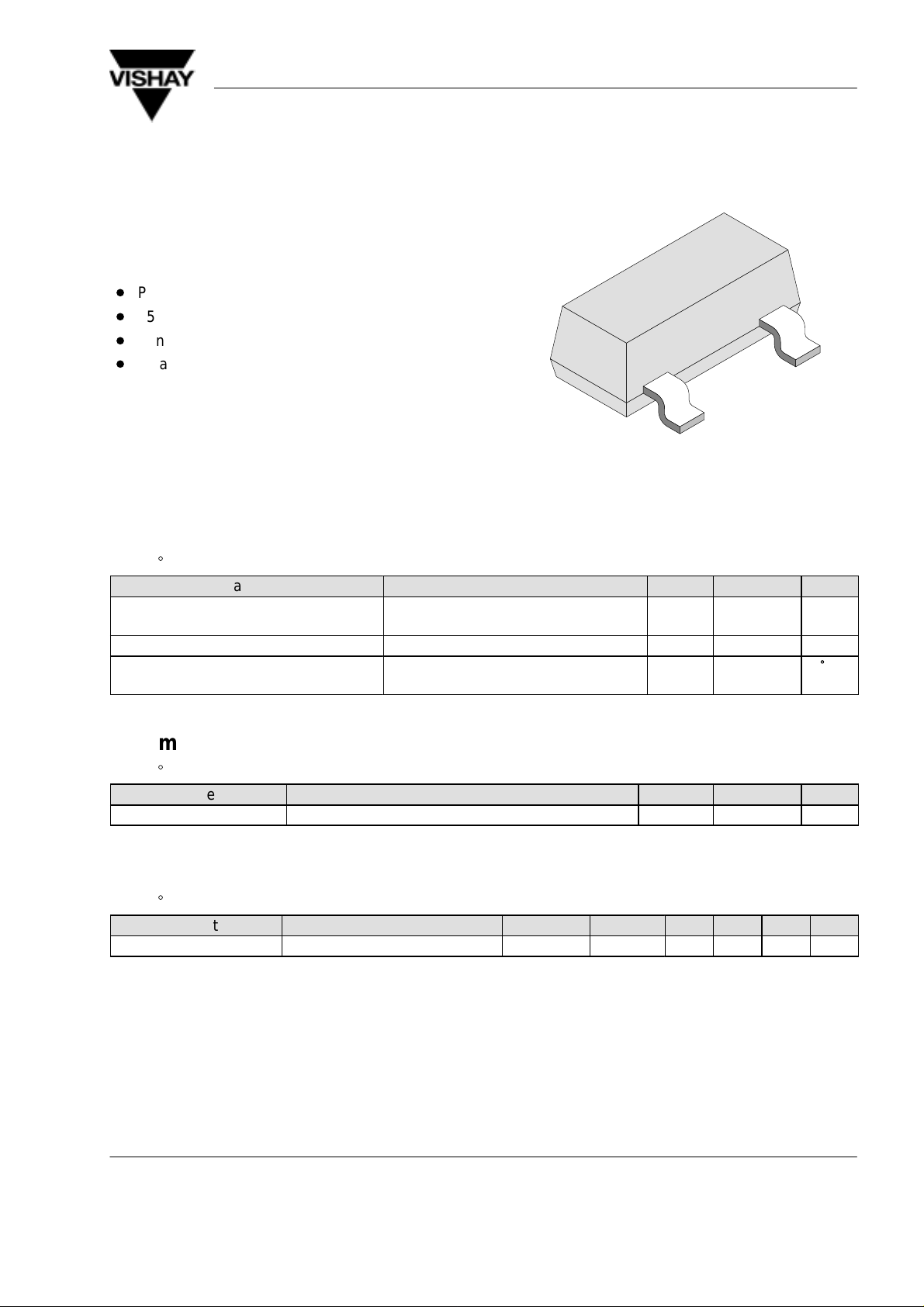
BZX84C2V7–BZX84C51
350 mW Surface Mount Zener Diodes
Features
D
Planar die construction
D
350 mW Power dissipation
D
Zener voltages from 2.7V – 51V
D
Ideally suited for automated assembly processes
Vishay Telefunken
94 8550
Absolute Maximum Ratings
Tj = 25_C
Parameter Test Conditions Symbol Value Unit
Power dissipation on ceramic substrate
10mm x 8mm x 0.7mm
Zener current (see figures 1–3 below)
Junction and storage
temperature range
Maximum Thermal Resistance
Tj = 25_C
Parameter Test Conditions Symbol Value Unit
Junction ambient on ceramic substrate 10mm x 8mm x 0.7mm R
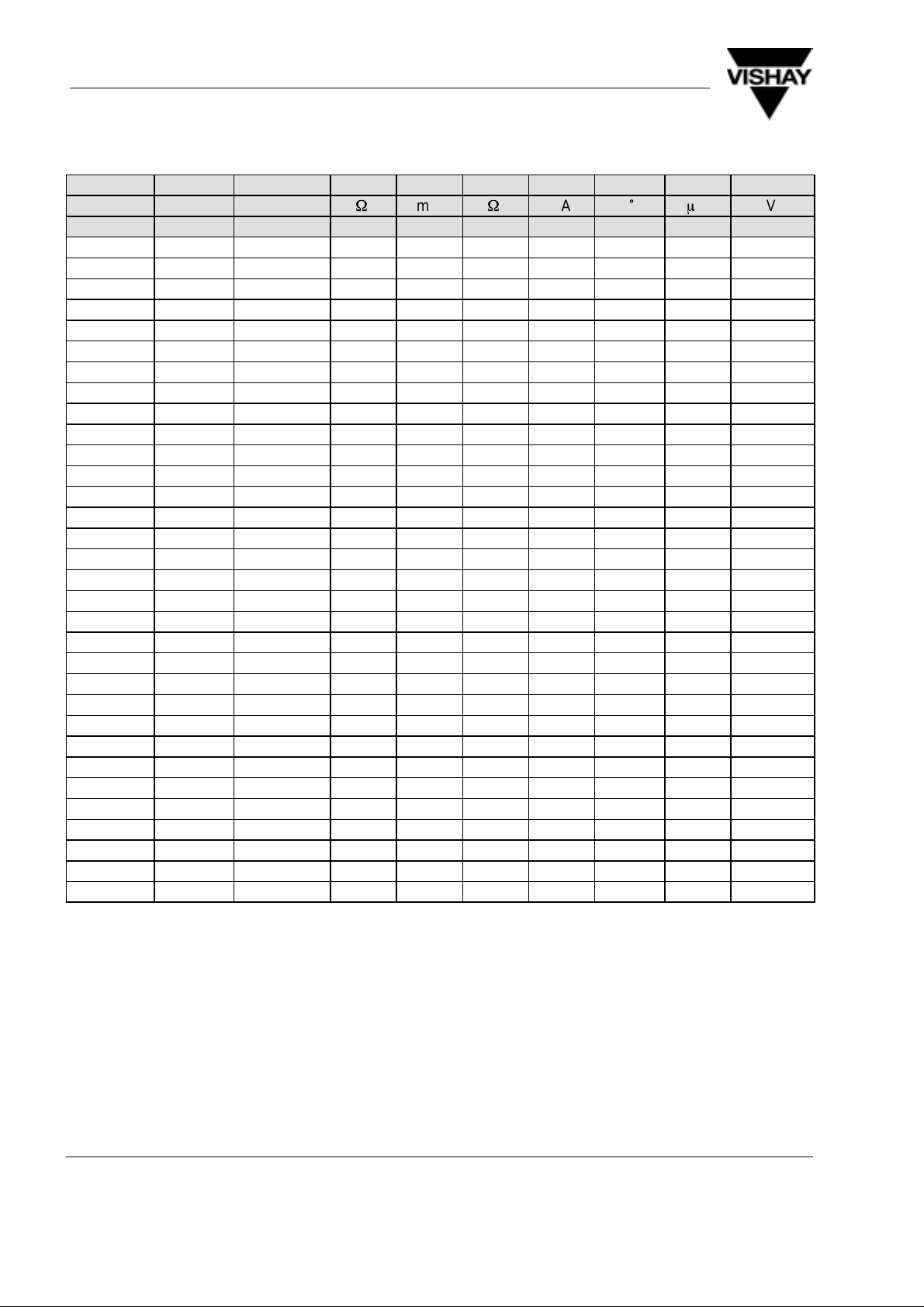
Electrical Characteristics
Tj = 25_C
Parameter Test Conditions Type Symbol Min Typ Max Unit
Forward Voltage IF=10 mA V
F
P
Tj=T
thJA
d
stg
350 mW
–55...+150
420 K/W
0.9 V
°
C
Document Number 85606
Rev. 1, 01-Apr-99 1 (5)
www.vishay.de • FaxBack +1-408-970-5600
BZX84C2V7–BZX84C51
Vishay Telefunken
Type Marking V
BZX84C... V
@ I
Z
ZT
Z
ZT
W
@ I
mA
ZT
Z
ZK
W
@ I
ZK
T
mA %/°C
C
I
R
m
A V
2V7 KZC 2.5 to 2.9 100 5.0 600 1.0 –0.065 20 1.0
3V0 KZD 2.8 to 3.2 100 5.0 600 1.0 –0.060 10 1.0
3V3 KZE 3.1 to 3.5 95 5.0 600 1.0 –0.055 5.0 1.0
3V6 KZF 3.4 to 3.8 95 5.0 600 1.0 –0.055 5.0 1.0
3V9 KZG 3.7 to 4.1 90 5.0 600 1.0 –0.050 3.0 1.0
4V3 KZH 4.0 to 4.6 90 5.0 600 1.0 –0.035 3.0 1.0
4V7 KZ1 4.4 to 5.0 80 5.0 500 1.0 –0.015 4.0 2.0
5V1 KZ2 4.8 to 5.4 60 5.0 480 1.0 +0.005 2.0 2.0
5V6 KZ3 5.2 to 6.0 40 5.0 400 1.0 +0.020 1.0 2.0
6V2 KZ4 5.8 to 6.6 10 5.0 150 1.0 +0.030 3.0 4.0
6V8 KZ5 6.4 to 7.2 15 5.0 80 1.0 +0.045 2.0 4.0
7V5 KZ6 7.0 to 7.9 15 5.0 80 1.0 +0.050 1.0 5.0
8V2 KZ7 7.7 to 8.7 15 5.0 80 1.0 +0.055 0.7 5.0
9V1 KZ8 8.5 to 9.6 15 5.0 100 1.0 +0.065 0.5 6.0
10 KZ9 9.4 to 10.6 20 5.0 150 1.0 +0.065 0.2 7.0
11 KY1 10.4 to 11.6 20 5.0 150 1.0 +0.070 0.1 8.0
12 KY2 11.4 to 12.7 25 5.0 150 1.0 +0.075 0.1 8.0
13 KY3 12.4 to 14.1 30 5.0 170 1.0 +0.080 0.1 8.0
15 KY4 13.8 to 15.6 30 5.0 200 1.0 +0.080 0.05 0.7V
16 KY5 15.3 to 17.1 40 5.0 200 1.0 +0.090 0.05 0.7V
18 KY6 16.8 to 19.1 45 5.0 225 1.0 +0.090 0.05 0.7V
20 KY7 18.8 to 21.2 55 5.0 225 1.0 +0.090 0.05 0.7V
22 KY8 20.8 to 23.3 55 5.0 250 1.0 +0.090 0.05 0.7V
24 KY9 22.8 to 25.6 70 5.0 250 1.0 +0.090 0.05 0.7V
27 KYA 25.1 to 28.9 80 2.0 300 0.5 +0.090 0.05 0.7V
30 KYB 28 to 32 80 2.0 300 0.5 +0.090 0.05 0.7V
33 KYC 31 to 35 80 2.0 325 0.5 +0.090 0.05 0.7V
36 KYD 34 to 38 90 2.0 350 0.5 +0.090 0.05 0.7V
39 KYE 37 to 41 130 2.0 350 0.5 +0.110 0.05 0.7V
43 KYF 40 to 46 150 2.0 375 0.5 +0.110 0.05 0.7V
47 KYG 44 to 50 170 2.0 375 0.5 +0.110 0.05 0.7V
51 KYH 48 to 54 180 2.0 400 0.5 +0.110 0.05 0.7V
@ V
R
Znom
Znom
Znom
Znom
Znom
Znom
Znom
Znom
Znom
Znom
Znom
Znom
Znom
Znom
1) Device mounted on ceramic substrate 8mmx10mmx0.7mm
2) VZ measured at IZT using a pulse test. IZ pulse width = 5 ms. Standard voltage tolerance is 5%.
www.vishay.de • FaxBack +1-408-970-5600 Document Number 85606
Rev. 1, 01-Apr-992 (5)

BZX84C2V7–BZX84C51
Characteristics (Tj = 25_C unless otherwise specified)
Vishay Telefunken
15251
50
Tj=25°C
C2V7
C3V3
C3V9
C4V7
40
30
20
Z
Test Current I
I – Z-Current ( mA )
10
5.0mA
z
0
0
12345678910
VZ – Z-Voltage ( V )
Figure 1. Z–Current vs. Z–Voltage
30
Tj=25°C
C10
C12
20
10
Test Current I
Z
I – Z-Current ( mA )
5.0mA
C15
C18
C22
z
C5V6
C6V8
C27
C8V2
Test Current I
2.0mA
C33
C36
500
400
See Note 1
300
200
100
tot
P – Total Power Dissipation ( mW )
0
100
200
15254
0
T
– Ambient Temperature ( °C )
amb
Figure 4. Total Power Dissipation vs.
Ambient Temperature
1000
V
= 1V
R
VR = 2V
100
z
D
C – Diode Capacitance ( pF )
VR = 2V
V
= 1V
R
Tj=25°C
15252
0
0
10 20 30 40
VZ – Z-Voltage ( V )
Figure 2. Z–Current vs. Z–Voltage
10
Tj=25°C
C39
C43
C47
C51
15255
10
1
10
VZ – Z-Voltage ( V )
Figure 5. Diode Capacitance vs. Z–Voltage
100
8
6
4
Test Current I
Z
I – Z-Current ( mA )
2
2.0mA
z
0
0
15253
10 20 30 40 50 60 70 80 90 100
VZ – Z-Voltage ( V )
Figure 3. Z–Current vs. Z–Voltage
Document Number 85606
Rev. 1, 01-Apr-99 3 (5)
www.vishay.de • FaxBack +1-408-970-5600

BZX84C2V7–BZX84C51
Vishay Telefunken
Dimensions in mm
top view
Case: SOT23, molded plastic
Mounting position: any
Approx. weight: 0.008 grams
14370
www.vishay.de • FaxBack +1-408-970-5600 Document Number 85606
Rev. 1, 01-Apr-994 (5)

BZX84C2V7–BZX84C51
Vishay Telefunken
Ozone Depleting Substances Policy Statement
It is the policy of Vishay Semiconductor GmbH to
1. Meet all present and future national and international statutory requirements.
2. Regularly and continuously improve the performance of our products, processes, distribution and operating
systems
with respect to their impact on the health and safety of our employees and the public, as well as their impact on
the environment.
It is particular concern to control or eliminate releases of those substances into the atmosphere which are known as
ozone depleting substances (ODSs).
The Montreal Protocol (1987) and its London Amendments (1990) intend to severely restrict the use of ODSs and
forbid their use within the next ten years. V arious national and international initiatives are pressing for an earlier ban
on these substances.
Vishay Semiconductor GmbH has been able to use its policy of continuous improvements to eliminate the use of
ODSs listed in the following documents.
1. Annex A, B and list of transitional substances of the Montreal Protocol and the London Amendments respectively
2. Class I and II ozone depleting substances in the Clean Air Act Amendments of 1990 by the Environmental
Protection Agency (EPA) in the USA
3. Council Decision 88/540/EEC and 91/690/EEC Annex A, B and C (transitional substances) respectively.
Vishay Semiconductor GmbH can certify that our semiconductors are not manufactured with ozone depleting
substances and do not contain such substances.
We reserve the right to make changes to improve technical design and may do so without further notice.
Parameters can vary in different applications. All operating parameters must be validated for each customer application
by the customer. Should the buyer use Vishay-Telefunken products for any unintended or unauthorized application, the
buyer shall indemnify Vishay-Telefunken against all claims, costs, damages, and expenses, arising out of, directly or
indirectly , any claim of personal damage, injury or death associated with such unintended or unauthorized use.
Vishay Semiconductor GmbH, P.O.B. 3535, D-74025 Heilbronn, Germany
Telephone: 49 (0)7131 67 2831, Fax number: 49 (0)7131 67 2423
Document Number 85606
Rev. 1, 01-Apr-99 5 (5)
www.vishay.de • FaxBack +1-408-970-5600

WWW.ALLDATASHEET.COM
Copyright © Each Manufacturing Company.
All Datasheets cannot be modified without permission.
This datasheet has been download from :
www.AllDataSheet.com
100% Free DataSheet Search Site.
Free Download.
No Register.
Fast Search System.
www.AllDataSheet.com
 Loading...