

Page 1
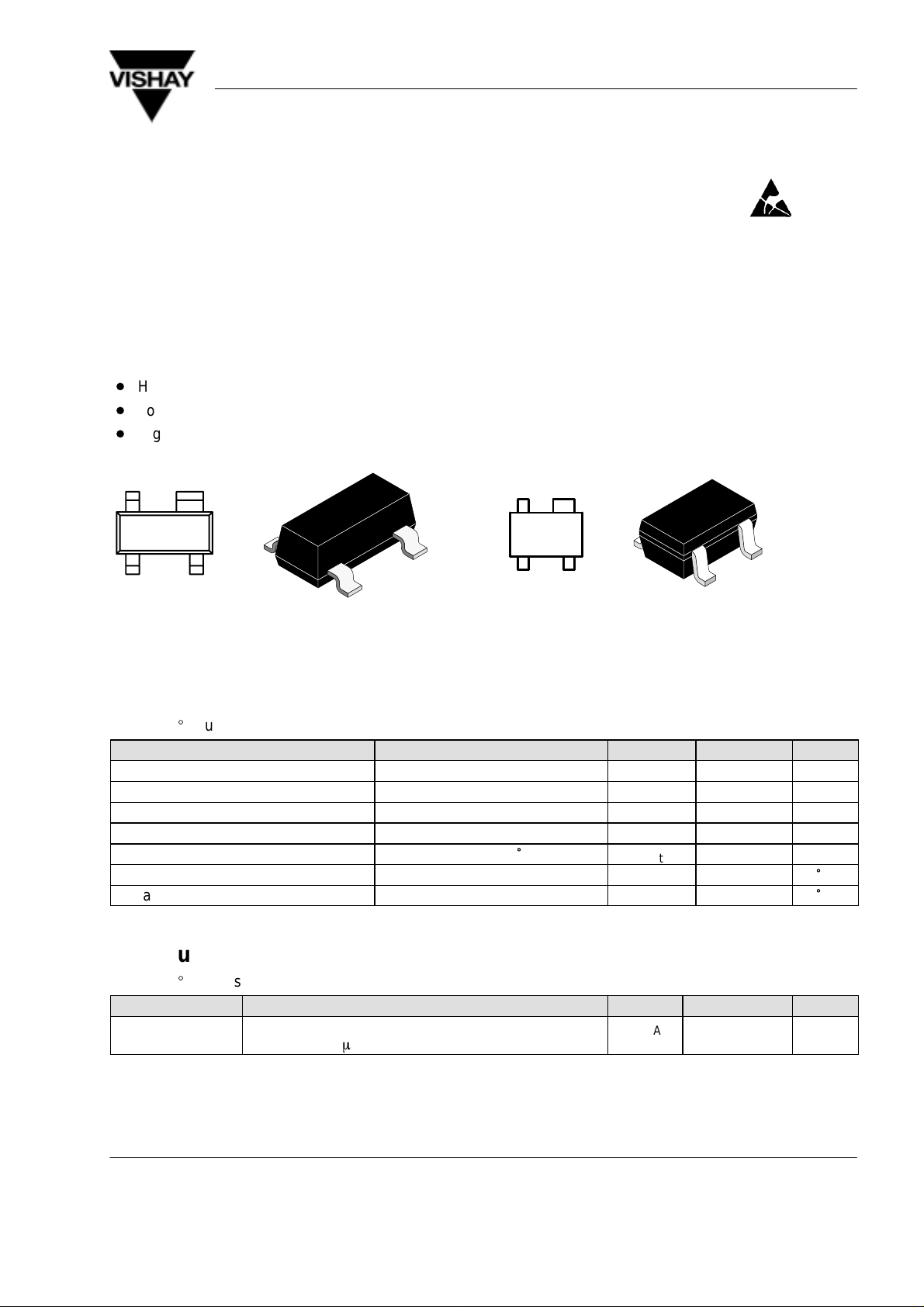
Silicon NPN Planar RF Transistor
Electrostatic sensitive device.
Observe precautions for handling.
Applications
RF amplifier up to GHz range, especially for wide band
antenna amplifiers.
Features
D
High power gain
D
Low noise figure
D
High transition frequency
BFP92A/BFP92AW
Vishay Telefunken
21
94 9279
13 579
43
BFP92A Marking: 92V
Plastic case (SOT 143)
1 = Collector, 2 = Emitter, 3 = Base, 4 = Emitter
BFP92AW Marking: W92
Plastic case (SOT 343)
1 = Collector, 2 = Emitter, 3 = Base, 4 = Emitter
1
2
13 653
4
3
Absolute Maximum Ratings
T
= 25_C, unless otherwise specified
amb
Parameter Test Conditions Symbol Value Unit
Collector-base voltage V
Collector-emitter voltage V
Emitter-base voltage V
Collector current I
Total power dissipation T
Junction temperature T
Storage temperature range T
≤ 60 °C P
amb
CBO
CEO
EBO
C
tot
j
stg
13 566
20 V
15 V
2 V
30 mA
200 mW
150
–65 to +150
°
C
°
C
Maximum Thermal Resistance
T
= 25_C, unless otherwise specified
amb
Parameter T est Conditions Symbol Value Unit
Junction ambient on glass fibre printed board (25 x 20 x 1.5) mm
plated with 35mm Cu
Document Number 85019
Rev. 3, 20-Jan-99
3
R
thJA
www.vishay.de • FaxBack +1-408-970-5600
450 K/W
1 (10)
Page 2
BFP92A/BFP92AW
Vishay Telefunken
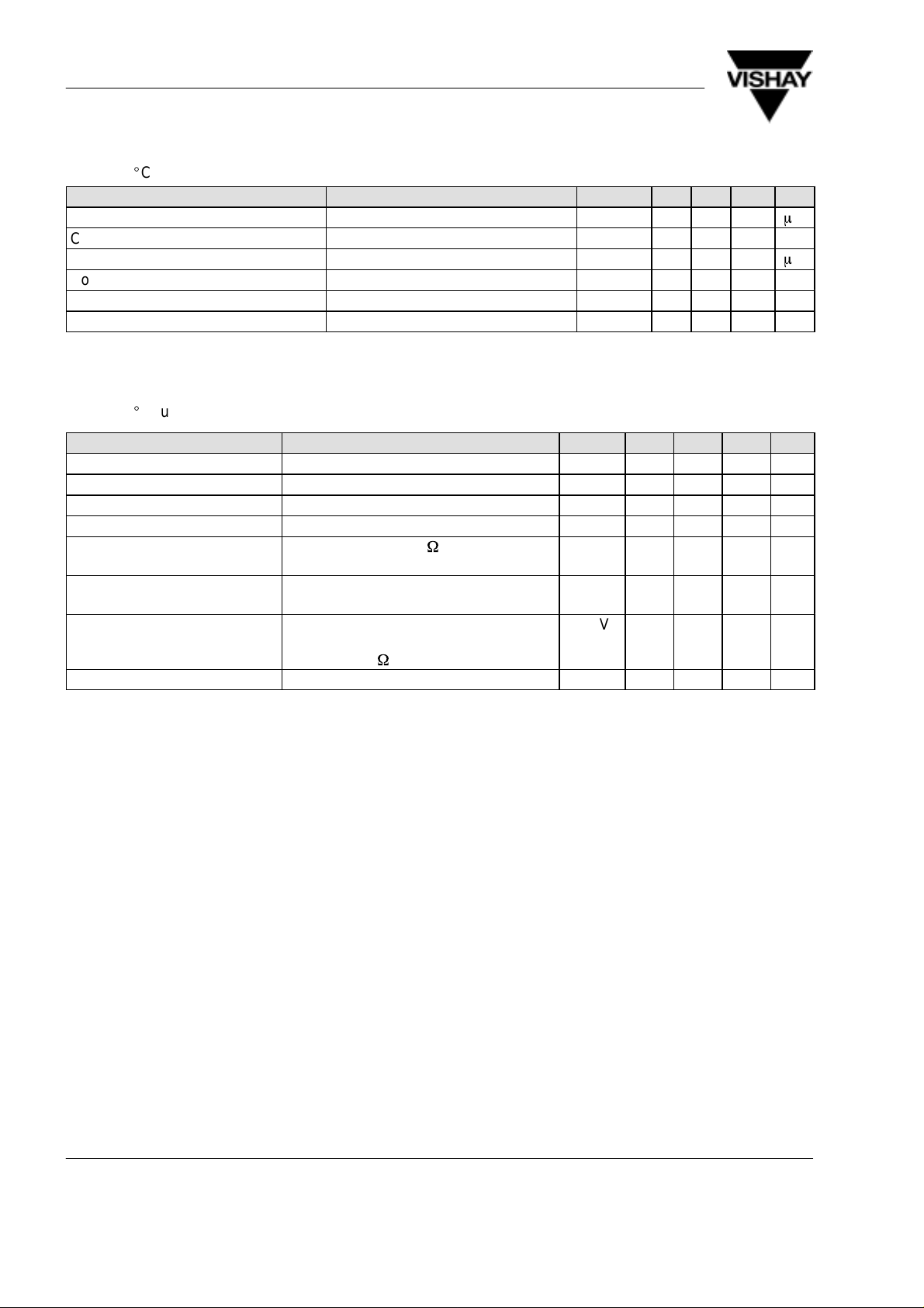
Electrical DC Characteristics
T
= 25_C, unless otherwise specified
amb
Parameter Test Conditions Symbol Min Typ Max Unit
Collector cut-off current VCE = 20 V, VBE = 0 I
Collector-base cut-off current VCB = 15 V, IE = 0 I
Emitter-base cut-off current VEB = 2 V, IC = 0 I
Collector-emitter breakdown voltage IC = 1 mA, IB = 0 V
Collector-emitter saturation voltage IC = 30 mA, IB = 3 mA V
DC forward current transfer ratio VCE = 10 V, IC = 14 mA h
Electrical AC Characteristics
T
= 25_C, unless otherwise specified
amb
Parameter Test Conditions Symbol Min Typ Max Unit
Transition frequency VCE = 10 V, IC = 14 mA, f = 500 MHz f
Collector-base capacitance VCB = 10 V, f = 1 MHz C
Collector-emitter capacitance VCE = 10 V, f = 1 MHz C
Emitter-base capacitance VEB = 0.5 V, f = 1 MHz C
Noise figure VCE = 10 V, ZS = 50 W, f = 800 MHz,
IC = 2 mA
Power gain VCE = 10 V, ZL = Z
, IC = 14 mA,
Lopt
f = 800 MHz
Linear output voltage – two
tone intermodulation test
VCE = 10 V, IC = 14 mA, dIM = 60 dB,
f1 = 806 MHz, f2 = 810 MHz,
ZS = ZL = 50
W
Third order intercept point VCE = 10 V, IC = 14 mA, f = 800 MHz IP
F 1.8 dB
G
V1 = V
CES
CBO
EBO
(BR)CEO
CEsat
FE
T
cb
ce
eb
pe
2
3
100mA
100 nA
10
m
15 V
0.1 0.4 V
50 100 150
6 GHz
0.25 pF
0.2 pF
0.7 pF
18 dB
120 mV
24 dBm
A
www.vishay.de • FaxBack +1-408-970-5600
2 (10)
Document Number 85019
Rev. 3, 20-Jan-99
Page 3
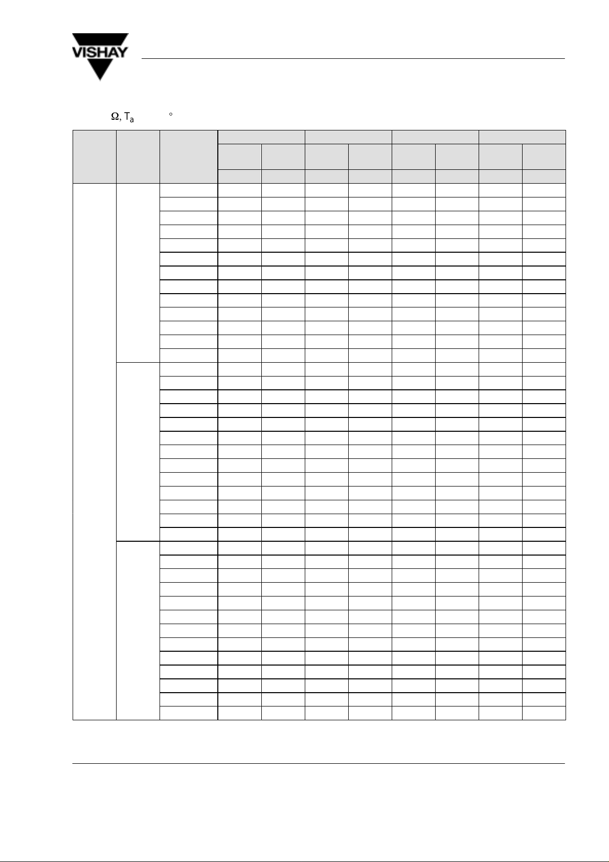
Common Emitter S–Parameters
BFP92A/BFP92AW
Vishay Telefunken
Z0 = 50 W,T
VCE/V IC/mA f/MHz
5 5 1500 0.415 178.0 3.29 69.7 0.078 41.8 0.490 –35.8
= 25_C, unless otherwise specified
amb
S11 S21 S12 S22
LIN
MAG
100 0.905 –16.8 6.54 165.6 0.019 78.3 0.973 –6.9
300 0.795 –47.3 5.72 142.2 0.049 60.4 0.896 –17.2
500 0.677 –72.7 4.83 124.5 0.068 48.5 0.802 –23.3
800 0.552 –103.8 3.76 105.3 0.083 37.3 0.707 –28.7
1000 0.499 –121.0 3.24 95.7 0.088 33.1 0.671 –31.4
1200 0.478 –136.4 2.84 87.2 0.092 29.9 0.643 –33.9
2 1500 0.463 –156.6 2.43 75.5 0.096 26.7 0.614 –37.9
1800 0.464 –173.5 2.10 66.0 0.098 25.1 0.592 –42.2
2000 0.478 177.2 1.94 59.6 0.100 24.9 0.583 –45.4
2200 0.492 166.5 1.81 53.5 0.100 24.9 0.578 –48.3
2500 0.501 153.6 1.64 44.5 0.107 25.2 0.572 –53.5
2800 0.532 143.0 1.49 36.3 0.106 24.8 0.569 –59.9
3000 0.550 136.4 1.40 31.6 0.108 24.8 0.556 –64.3
100 0.790 –27.1 14.00 159.0 0.017 74.0 0.942 –11.7
300 0.619 –72.1 10.70 129.4 0.039 54.0 0.765 –24.6
500 0.499 –103.6 8.01 111.4 0.050 45.9 0.634 –28.1
800 0.427 –137.5 5.60 94.6 0.059 42.3 0.549 –29.8
1000 0.405 –152.9 4.65 86.6 0.065 41.8 0.524 –31.0
1200 0.405 –166.6 3.98 79.5 0.070 41.8 0.508 –32.3
1800 0.430 165.6 2.80 61.5 0.086 42.1 0.474 –39.9
2000 0.447 157.7 2.57 55.9 0.092 41.7 0.469 –43.1
2200 0.465 149.9 2.38 50.7 0.097 41.8 0.465 –46.1
2500 0.484 140.2 2.12 42.8 0.109 38.9 0.459 –51.9
2800 0.518 130.8 1.92 35.3 0.113 38.7 0.455 –58.4
3000 0.533 126.3 1.80 31.1 0.117 37.7 0.443 –62.8
100 0.647 –41.7 22.60 151.4 0.015 69.2 0.889 –16.7
300 0.475 –100.6 14.47 118.3 0.030 52.9 0.637 –28.3
500 0.410 –133.3 9.86 102.2 0.038 50.1 0.519 –27.9
800 0.390 –161.5 6.55 88.2 0.048 51.4 0.462 –26.9
1000 0.385 –174.9 5.35 81.3 0.055 52.4 0.451 –27.6
1200 0.394 175.6 4.53 75.1 0.062 52.8 0.442 –28.9
10 1500 0.414 164.5 3.70 66.4 0.074 52.3 0.432 –32.6
1800 0.435 153.5 3.13 58.9 0.084 51.7 0.421 –36.8
2000 0.447 148.0 2.86 53.7 0.092 50.8 0.418 –40.3
2200 0.468 141.7 2.64 49.0 0.098 49.5 0.416 –43.3
2500 0.491 133.6 2.36 41.7 0.111 46.2 0.410 –49.4
2800 0.522 126.2 2.12 34.6 0.116 45.2 0.404 –56.2
3000 0.538 122.0 1.98 30.7 0.122 43.8 0.392 –60.7
ANG
deg deg deg deg
LIN
MAG
ANG
LIN
MAG
ANG
LIN
MAG
ANG
Document Number 85019
Rev. 3, 20-Jan-99
www.vishay.de • FaxBack +1-408-970-5600
3 (10)
Page 4

BFP92A/BFP92AW
Vishay Telefunken
S1 1 S21 S12 S22
VCE/V IC/mA f/MHz
100 0.561 –51.8 26.86 147.2 0.013 67.9 0.856 –19.1
300 0.431 –115.6 15.65 113.6 0.026 53.2 0.584 –28.5
500 0.398 –146.2 10.34 98.7 0.034 53.7 0.483 –26.3
800 0.391 –171.1 6.75 85.8 0.045 55.9 0.441 –24.8
1000 0.392 177.6 5.50 79.3 0.053 56.9 0.435 –25.3
1200 0.401 169.2 4.65 73.3 0.061 57.1 0.430 –26.9
14 1500 0.423 159.4 3.79 65.1 0.072 56.2 0.421 –30.7
1800 0.440 150.1 3.20 57.8 0.083 54.7 0.413 –35.3
2000 0.455 145.6 2.91 52.7 0.091 53.6 0.410 –38.9
2200 0.478 139.1 2.68 48.2 0.098 52.4 0.408 –42.0
2500 0.499 131.7 2.40 40.9 0.111 49.2 0.403 –48.3
2800 0.533 124.3 2.15 33.9 0.116 47.3 0.396 –55.1
3000 0.546 120.6 2.01 30.0 0.122 46.0 0.383 –59.6
100 0.478 –65.7 30.79 142.2 0.012 65.1 0.817 –21.1
300 0.411 –131.9 16.24 109.1 0.023 55.1 0.542 –26.9
500 0.402 –158.4 10.48 95.5 0.030 57.7 0.462 –23.5
800 0.404 –178.7 6.75 83.5 0.042 60.5 0.436 –22.0
1000 0.408 171.6 5.48 77.5 0.050 61.0 0.433 –23.0
1200 0.423 164.2 4.62 71.6 0.059 60.6 0.431 –24.8
5 20 1500 0.440 155.4 3.77 63.6 0.070 59.2 0.425 –29.1
1800 0.460 147.0 3.17 56.5 0.082 57.7 0.417 –33.8
2000 0.476 142.7 2.89 51.7 0.090 56.1 0.415 –37.5
2200 0.496 137.1 2.66 46.9 0.097 54.8 0.413 –40.8
2500 0.514 129.7 2.36 39.6 0.109 51.4 0.409 –47.0
2800 0.548 123.0 2.12 33.0 0.115 49.5 0.402 –54.0
3000 0.562 119.2 1.99 29.12 0.121 48.0 0.390 –58.5
100 0.413 –89.8 32.20 135.2 0.010 63.8 0.766 –21.5
300 0.427 –149.8 15.29 104.0 0.019 57.7 0.530 –21.9
500 0.433 –170.2 9.65 91.9 0.027 62.2 0.480 –18.6
800 0.445 173.9 6.17 80.9 0.038 64.9 0.467 –18.7
1000 0.449 165.9 5.01 75.2 0.047 65.0 0.467 –20.5
1200 0.459 159.6 4.22 69.5 0.055 64.8 0.467 –22.8
30 1500 0.478 152.2 3.42 61.5 0.066 62.9 0.461 –27.5
1800 0.500 144.4 2.87 54.5 0.078 60.9 0.455 –32.7
2000 0.516 140.5 2.61 49.5 0.085 59.7 0.453 –36.4
2200 0.541 134.6 2.41 44.8 0.092 58.0 0.452 –39.8
2500 0.556 127.8 2.15 37.8 0.105 54.6 0.447 –46.1
2800 0.588 121.4 1.92 30.9 0.110 53.1 0.444 –53.2
3000 0.601 117.5 1.80 27.0 0.116 51.8 0.431 –57.8
LIN
MAG
ANG
deg deg deg deg
LIN
MAG
ANG
LIN
MAG
ANG
LIN
MAG
ANG
www.vishay.de • FaxBack +1-408-970-5600
4 (10)
Document Number 85019
Rev. 3, 20-Jan-99
Page 5

BFP92A/BFP92AW
Vishay Telefunken
S1 1 S21 S12 S22
VCE/V IC/mA f/MHz
100 0.916 –15.8 6.53 166.1 0.015 78.4 0.975 –5.9
300 0.805 –45.0 5.76 143.2 0.041 61.9 0.912 –14.5
500 0.686 –69.6 4.87 125.6 0.057 49.8 0.833 –19.8
800 0.554 –100.1 3.84 106.6 0.069 39.8 0.751 –24.8
1000 0.496 –117.1 3.31 97.0 0.074 35.6 0.720 –27.2
1200 0.467 –132.6 2.92 88.4 0.078 32.9 0.699 –29.4
2 1500 0.451 –153.3 2.50 76.8 0.082 30.2 0.672 –33.5
1800 0.446 –171.1 2.16 67.3 0.084 29.2 0.654 –37.5
2000 0.456 178.9 2.00 61.0 0.086 29.0 0.646 –40.2
2200 0.473 168.5 1.86 55.1 0.087 29.0 0.642 –43.1
2500 0.487 154.5 1.68 46.0 0.090 29.4 0.638 –47.7
2800 0.518 143.4 1.54 37.8 0.093 31.1 0.642 –53.7
3000 0.533 137.3 1.45 33.4 0.095 31.5 0.630 –57.7
100 0.808 –25.3 13.94 159.8 0.014 74.5 0.950 –9.6
300 0.633 –67.8 10.82 130.7 0.033 55.5 0.803 –20.3
500 0.504 –98.6 8.18 112.5 0.042 48.0 0.690 –23.4
800 0.411 –131.6 5.74 95.6 0.051 44.6 0.618 –25.1
1000 0.387 –148.3 4.77 87.4 0.055 44.4 0.596 –26.4
1200 0.381 –162.1 4.09 80.3 0.061 44.6 0.584 –28.0
10 5 1500 0.389 –178.2 3.38 70.6 0.068 45.3 0.568 –31.5
1800 0.402 167.6 2.88 62.4 0.075 45.5 0.554 –35.6
2000 0.416 160.7 2.64 57.1 0.080 46.2 0.552 –38.4
2200 0.437 152.5 2.44 51.8 0.085 46.8 0.550 –41.6
2500 0.464 142.8 2.19 43.7 0.097 42.4 0.541 –47.0
2800 0.489 133.7 1.98 36.4 0.099 43.3 0.542 –53.1
3000 0.510 128.9 1.86 32.3 0.105 42.9 0.530 –57.2
100 0.680 –38.0 22.27 152.6 0.012 70.4 0.907 –13.5
300 0.488 –93.5 14.64 119.7 0.026 54.2 0.695 –22.7
500 0.402 –126.0 10.05 103.3 0.033 51.5 0.596 –22.4
800 0.365 –156.0 6.68 89.0 0.042 52.9 0.550 –22.3
1000 0.357 –169.7 5.47 81.9 0.048 54.5 0.539 –23.4
1200 0.365 179.8 4.62 75.8 0.055 55.1 0.535 –25.0
10 1500 0.388 167.7 3.80 67.1 0.065 53.6 0.522 –29.0
1800 0.402 156.4 3.20 59.6 0.073 53.5 0.513 –33.1
2000 0.415 150.4 2.92 55.0 0.079 53.6 0.514 –35.5
2200 0.437 144.1 2.70 50.2 0.086 53.1 0.513 –38.9
2500 0.465 135.9 2.42 42.7 0.098 49.7 0.509 –44.5
2800 0.492 128.3 2.18 35.6 0.102 49.0 0.505 –50.8
3000 0.518 124.3 2.04 31.9 0.108 47.9 0.492 –54.8
LIN
MAG
ANG
deg deg deg deg
LIN
MAG
ANG
LIN
MAG
ANG
LIN
MAG
ANG
Document Number 85019
Rev. 3, 20-Jan-99
www.vishay.de • FaxBack +1-408-970-5600
5 (10)
Page 6

BFP92A/BFP92AW
Vishay Telefunken
S1 1 S21 S12 S22
VCE/V IC/mA f/MHz
100 0.605 –47.0 26.73 148.2 0.011 68.5 0.879 –15.4
300 0.436 –108.4 15.89 144.6 0.023 54.4 0.651 –22.2
500 0.381 –139.9 10.54 99.4 0.029 54.5 0.566 –20.7
800 0.364 –166.4 6.88 86.3 0.039 57.0 0.534 –20.4
1000 0.363 –178.7 5.60 79.8 0.046 58.7 0.529 –21.5
1200 0.370 172.5 4.73 74.1 0.053 59.3 0.527 –23.4
14 1500 0.393 162.0 3.87 65.7 0.064 57.3 0.518 –27.7
1800 0.412 152.2 3.26 58.3 0.073 56.6 0.509 –31.7
2000 0.424 146.4 2.95 53.8 0.078 56.6 0.509 –34.2
2200 0.448 140.6 2.73 48.9 0.085 55.8 0.509 –37.9
2500 0.474 133.9 2.45 41.8 0.097 52.2 0.505 –43.6
2800 0.502 126.1 2.21 34.8 0.102 51.5 0.502 –49.9
3000 0.522 122.1 2.07 31.1 0.108 49.9 0.490 –53.9
100 0.535 –58.5 30.52 143.2 0.011 67.4 0.848 –16.6
300 0.406 –123.4 16.42 109.9 0.020 55.7 0.620 –20.5
500 0.379 –152.2 10.60 96.0 0.026 58.1 0.556 –18.3
800 0.376 –175.1 6.84 83.9 0.037 61.2 0.535 –18.4
1000 0.377 175.0 5.56 77.9 0.044 62.2 0.535 –20.0
1200 0.387 167.5 4.68 72.4 0.052 62.5 0.536 –21.9
10 20 1500 0.409 158.0 3.81 64.1 0.061 60.4 0.527 –26.4
1800 0.430 148.5 3.21 57.1 0.070 59.5 0.519 –30.6
2000 0.443 144.2 2.91 52.4 0.077 59.0 0.520 –33.6
2200 0.470 138.9 2.69 47.8 0.084 58.1 0.520 –37.0
2500 0.489 131.7 2.40 40.5 0.096 54.4 0.516 –42.7
2800 0.525 124.7 2.16 33.6 0.101 53.7 0.513 –49.1
3000 0.540 121.6 2.02 30.1 0.107 52.3 0.501 –53.2
100 0.463 –77.4 32.39 136.5 0.009 62.5 0.810 –16.7
300 0.410 –141.2 15.52 104.8 0.017 57.7 0.618 –16.7
500 0.403 –164.4 9.79 92.5 0.023 61.9 0.577 –15.0
800 0.409 177.5 6.28 81.4 0.034 65.1 0.568 –16.4
1000 0.415 168.5 5.08 75.6 0.041 66.2 0.568 –18.4
1200 0.426 162.7 4.27 70.2 0.049 65.9 0.569 –20.9
30 1500 0.448 154.5 3.47 62.2 0.058 63.9 0.562 –25.4
1800 0.472 146.2 2.92 55.2 0.067 63.2 0.554 –29.9
2000 0.484 141.7 2.66 50.7 0.073 62.5 0.554 –33.1
2200 0.504 136.3 2.45 46.0 0.080 61.7 0.556 –36.5
2500 0.533 129.5 2.18 38.7 0.091 57.6 0.554 –42.2
2800 0.565 123.1 1.97 32.0 0.096 57.5 0.553 –48.7
3000 0.581 119.5 1.84 28.1 0.103 56.4 0.540 –52.8
LIN
MAG
ANG
deg deg deg deg
LIN
MAG
ANG
LIN
MAG
ANG
LIN
MAG
ANG
www.vishay.de • FaxBack +1-408-970-5600
6 (10)
Document Number 85019
Rev. 3, 20-Jan-99
Page 7

BFP92A/BFP92AW
Vishay Telefunken
Typical Characteristics (T
300
250
200
150
100
50
tot
P – Total Power Dissipation ( mW )
0
0 20 40 60 80 100 120 140 160
T
– Ambient Temperature ( °C )96 12159
amb
Figure 1. Total Power Dissipation vs.
Ambient Temperature
7000
6000
5000
VCE=10V
f=500MHz
= 25_C unless otherwise specified)
amb
1.0
f=1MHz
0.8
0.6
0.4
0.2
cb
C – Collector Base Capacitance ( pF )
0
0 4 8 12 16 20
VCB – Collector Base Voltage ( V )12878
Figure 3. Collector Base Capacitance vs.
Collector Base Voltage
4
VCE=10V
f=800MHz
Z
=50
3
W
S
4000
3000
2000
1000
T
f – Transition Frequency ( MHz )
0
0 4 8 12 16 20
IC – Collector Current ( mA )12877
Figure 2. Transition Frequency vs. Collector Current
2
1
F – Noise Figure ( dB )
0
0 4 8 12 16 20
IC – Collector Current ( mA )12879
Figure 4. Noise Figure vs. Collector Current
Document Number 85019
Rev. 3, 20-Jan-99
www.vishay.de • FaxBack +1-408-970-5600
7 (10)
Page 8

BFP92A/BFP92AW
ÁÁ
Vishay Telefunken
VCE = 10 V, IC = 14 mA , Z0 = 50
S
11
j
S
21
j0.5
0.2
2.0
1.0
3.0 GHz
1
0.3
–j
j0.2
0
–j0.2
–j0.5
12 986
Figure 5. Input reflection coefficient
j2
2
5
0.1
–j5
–j2
W
S
12
90°
120°
150°
j5
1
180°
–150°
–120° –60°
12 987
2.0
1.0
0.1
–90°
Figure 7. Reverse transmission coefficient
S
22
60°
3.0 GHz
0.08 0.16
30°
0°
–30°
90°
120° 60°
0.1
180°
–150°
–120° –60°
12 988
0.3
0.5
3.0 GHz
–90°
1.0
10 20
Figure 6. Forward transmission coefficient
30°
–30°
j
j0.5
j0.2
0°
0
–j0.2
12 989
–j0.5
0.2
0.5
1
2.0
3.0 GHz
–j
j2
j5
2
5
1.0
0.3
–j2
1
0.1
–j5
Figure 8. Output reflection coefficient
www.vishay.de • FaxBack +1-408-970-5600
8 (10)
Document Number 85019
Rev. 3, 20-Jan-99
Page 9

Dimensions of BFP92A in mm
BFP92A/BFP92AW
Vishay Telefunken
Dimensions of BFP92AW in mm
96 12240
Document Number 85019
Rev. 3, 20-Jan-99
96 12237
www.vishay.de • FaxBack +1-408-970-5600
9 (10)
Page 10

BFP92A/BFP92AW
Vishay Telefunken
Ozone Depleting Substances Policy Statement
It is the policy of Vishay Semiconductor GmbH to
1. Meet all present and future national and international statutory requirements.
2. Regularly and continuously improve the performance of our products, processes, distribution and operating
systems with respect to their impact on the health and safety of our employees and the public, as well as their
impact on the environment.
It is particular concern to control or eliminate releases of those substances into the atmosphere which are known as
ozone depleting substances (ODSs).
The Montreal Protocol (1987) and its London Amendments (1990) intend to severely restrict the use of ODSs and
forbid their use within the next ten years. V arious national and international initiatives are pressing for an earlier ban
on these substances.
Vishay Semiconductor GmbH has been able to use its policy of continuous improvements to eliminate the use of
ODSs listed in the following documents.
1. Annex A, B and list of transitional substances of the Montreal Protocol and the London Amendments respectively
2. Class I and II ozone depleting substances in the Clean Air Act Amendments of 1990 by the Environmental
Protection Agency (EPA) in the USA
3. Council Decision 88/540/EEC and 91/690/EEC Annex A, B and C (transitional substances) respectively.
Vishay Semiconductor GmbH can certify that our semiconductors are not manufactured with ozone depleting
substances and do not contain such substances.
We reserve the right to make changes to improve technical design and may do so without further notice.
Parameters can vary in different applications. All operating parameters must be validated for each customer application
by the customer. Should the buyer use Vishay-Telefunken products for any unintended or unauthorized application, the
buyer shall indemnify Vishay-Telefunken against all claims, costs, damages, and expenses, arising out of, directly or
indirectly , any claim of personal damage, injury or death associated with such unintended or unauthorized use.
Vishay Semiconductor GmbH, P.O.B. 3535, D-74025 Heilbronn, Germany
Telephone: 49 (0)7131 67 2831, Fax number: 49 (0)7131 67 2423
www.vishay.de • FaxBack +1-408-970-5600
10 (10)
Document Number 85019
Rev. 3, 20-Jan-99
 Loading...