

I2124 rev. B 10/99
SURFACE MOUNTABLE
FAST SOFT RECOVERY
DIODE
Description/Features
The 8EWF..S fast soft recovery QUIETIR rectifier
series has been optimized for combined short
reverse recovery time, low forward voltage drop
and low leakage current
The glass passivation ensures stable reliable
operation in the most severe temperature and
power cycling conditions.
Typical applications are both:
Output rectification and freewheeling diode
in inverters, choppers and converters.
Input rectifications where severe
restrictions on conducted EMI should be met.
QUIET
V
F
t
rr
V
RRM
IR
Series
8EWF..S
< 1.2V @ 8A
= 55ns
200 to 600V
Major Ratings and Characteristics
Characteristics 8EWF..S Units
I
Sinusoidal waveform 8 A
F(AV)
V
RRM
I
FSM
VF@ 8 A, TJ = 25°C 1.2 V
trr@ 1A, 100A/µs 55 ns
T
J
200 to 600 V
170 A
- 40 to 150 °C
Package Outline
TO-252AA (D-Pak)
1
8EWF..S QUIET
t
I
FM
t
rr
Q
rr
I
rr
di
dt
tbta
IR
Series
I2124 rev. B 10/99
Voltage Ratings
V
Part Number
, maximum V
RRM
peak reverse voltage peak reverse voltage 150°C
, maximum non repetitive I
RSM
VVmA
8EWF02S 200 300 3
8EWF04S 400 500
8EWF06S 600 700
Absolute Maximum Ratings
Parameters 8EWF..S Units Conditions
I
Max. Average Forward Current 8 A @ TC = 96° C, 180° conduction half sine wave
F(AV)
I
Max. Peak One Cycle Non-Repetitive 170 10ms Sine pulse, rated V
FSM
A
Surge Current 200 10ms Sine pulse, no voltage reapplied
I2t Max. I2t for fusing 140 10ms Sine pulse, rated V
A2s
200 10ms Sine pulse, no voltage reapplied
I2√t Max. I2√t for fusing 2000 A2√s t = 0.1 to 10ms, no voltage reapplied
RRM
RRM
applied
applied
RRM
Electrical Specifications
Parameters 8EWF..S Units Conditions
VFMMax. Forward Voltage Drop 1.2 V @ 8A, TJ = 25°C
rtForward slope resistance 16 mΩ
V
Threshold voltage 1.13 V
F(TO)
IRMMax. Reverse Leakage Current 0.1 TJ = 25 °C
3T
mA
TJ = 150°C
= 150 °C
J
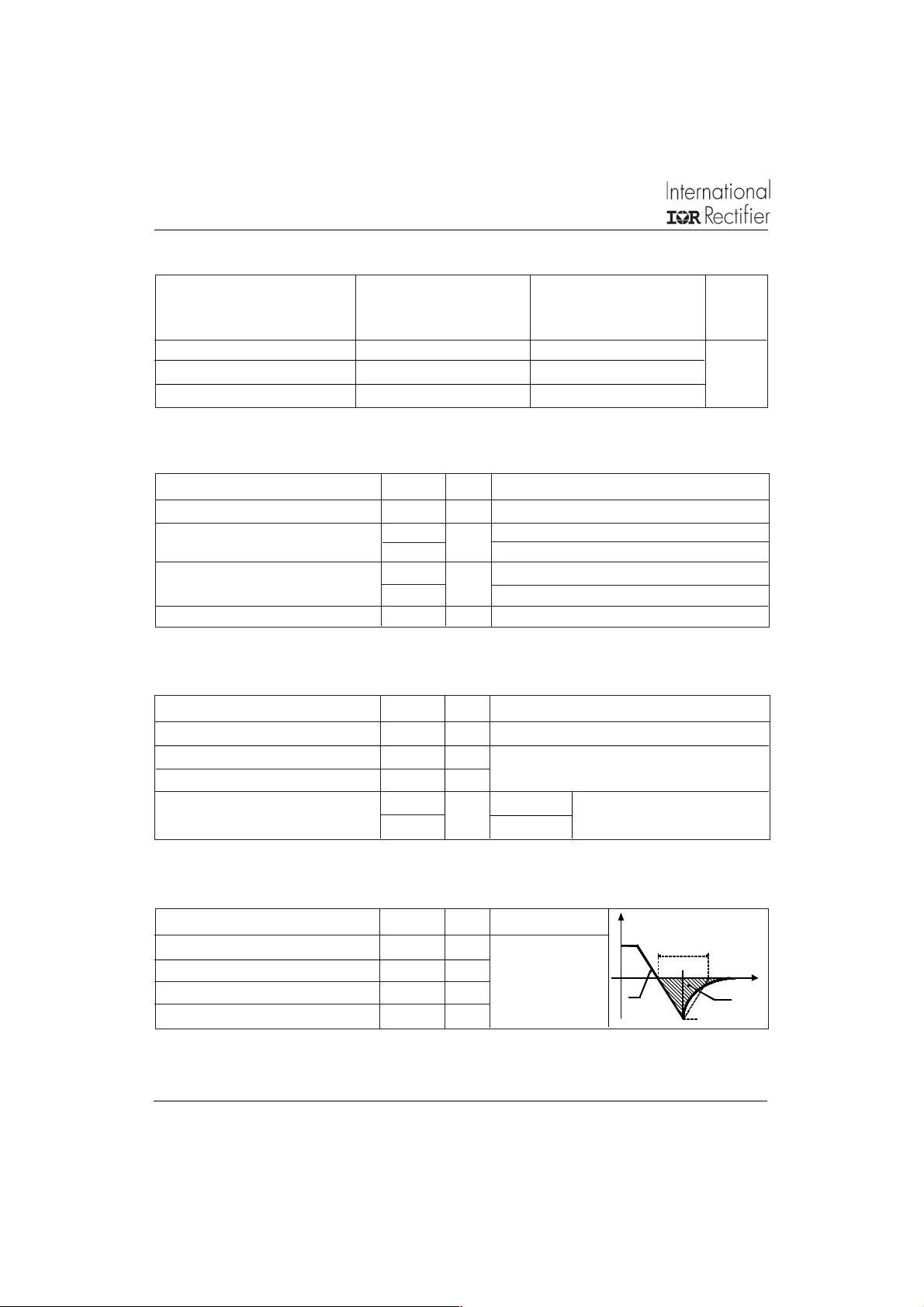
Typical Reverse Recovery Characteristics
Parameters 8EWF..S Units
trrReverse Recovery Time 140 ns IF @ 8Apk
IrrReverse Recovery Current 2.6 A @ 25A/µs
QrrReverse Recovery Charge 0.25 µC @ TJ = 25°C
S Snap Factor tb/ta 0.5 -
2
Conditions
VR = rated V
RRM
8EWF..S QUIET
Thermal-Mechanical Specifications
Parameters 8EWF..S Units Conditions
TJMax. Junction Temperature Range - 40 to 150 °C
Max. Storage Temperature Range - 40 to 150 °C
T
stg
Soldering Temperature 240 °C for 10 seconds
R
Max. Thermal Resistance Junction 2.5 °C/W DC operation
thJC
to Case
R
Typ. Thermal Resistance Junction 50 °C/W
thJA
to Ambient (PCB Mount)**
wt Approximate Weight 1(0.03) g (oz.)
Case Style TO-252AA (D-Pak)
**When mounted on 1" square (650mm2) PCB of FR-4 or G-10 material 4 oz (140µm) copper 40°C/W
For recommended footprint and soldering techniques refer to application note #AN-994
IR
Series
I2124 rev. B 10/99
150
140
130
120
110
100
90
80
70
60
Maximum Allowable Case Temperature (°C)
0123456789
Average Forward Current (A)
8EWF..S Series
R (DC) = 2.5 °C/W
thJC
Conduction Angle
30°
60°
90°
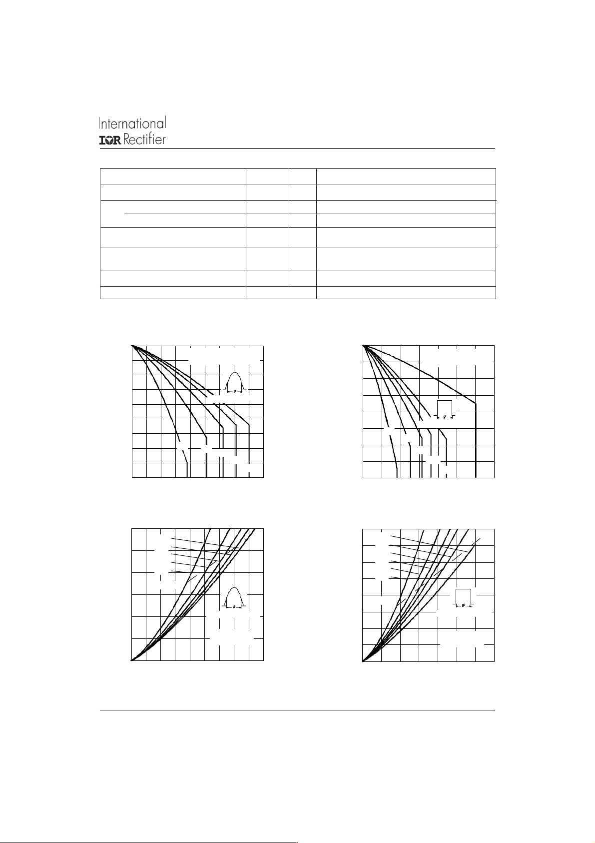
Fig. 1 - Current Rating Characteristics
12
180°
10
8
6
4
2
0
Maximum Average Forward P ower Loss (W)
120°
90°
60°
30°
RMS Limi t
Conduc t i o n Ang l e
8EWF..S Ser ie s
T = 150°C
J
0123456789
Average Forward Current (A)
Fig. 3 - Forward Power Loss Characteristics
120°
180°
150
140
130
120
110
Maximum Allowable Case Temperature (°C)
100
90
80
70
30°
02468101214
Average Forward Current (A)
8EW F. .S Series
R (DC) = 2.5 °C/W
thJC
Conduction Period
60°
90°
120°
180°
DC
Fig. 2 - Current Rating Characteristics
16
DC
180°
14
120°
90°
12
60°
30°
10
8
RMS Limit
6
4
2
0
Maximum Average Forward Power Loss (W)
02468101214
Average Forward Cu rrent (A)
Conduction P eriod
8EW F.. S Series
T = 150°C
J
Fig. 4 - Forward Power Loss Characteristics
3

8EWF..S QUIET
I2124 rev. B 10/99
IR
Series
200
At Any Rated Load Condition And With
Rated V Applied Follo wing Surge .
175
150
125
100
75
8EWF..S Series
Peak Half Sine Wave Forward Current (A)
50
1 10 100
Number Of E qu al Amplitude Half Cy cle Current Pul ses (N)
RRM
Initi a l T = 150°C
J
@ 60 Hz 0.0 083 s
@ 50 Hz 0.0 100 s
100
10
T = 25°C
J
T = 150°C
J
200
Maximum Non Repetitive Surge Current
180
160
140
120
100
80
8EWF..S Series
60
Peak Half Sine Wave Forward Current (A)
40
0.01 0.1 1
Versus Pulse Train Duration.
Pulse T rain Duration (s)
Initial T = 150°C
No Voltage Reapplied
Rated V Reapplied
RRM
Fig. 6 - Maximum Non-Repetitive Surge CurrentFig. 5 - Maximum Non-Repetitive Surge Current
J
Instantaneous Forward Current (A)
0.4
0.3
I = 20 A
FM
0.2
0.1
Maximum Reverse Recovery Time - Trr (µs)
0
0 40 80 120 160 200
Rate Of Fall Of Forward Current - di/dt (A /µs)
10 A
8 A
Fig. 8 - Recovery Time Characteristics, T
4
8EWF..S Series
1
0.511.522.53
Instant aneous Forward Voltage (V)
Fig. 7 - Forward Voltage Drop Characteristics
8EW F.. S Seri es
T = 25 °C
J
5 A
2 A
1 A
Maximu m Rever se Recovery Time - Trr (µs)
= 25°C Fig. 9 - Recovery Time Characteristics, TJ = 150°C
J
0.4
0.3
I = 20 A
FM
0.2
0.1
0
0 40 80 120 160 200
Rate Of Fall Of Fo rward Current - di/dt (A/µs)
10 A
8EWF..S Series
T = 150 °C
J
8 A
5 A
2 A
1 A

8EWF..S QUIET
I2124 rev. B 10/99
IR
Series
1.4
1.2
8EWF..S Series
T = 25 °C
J
I = 20 A
1
0.8
0.6
0.4
0.2
0
0 40 80 120 160 200
Maximum Reverse Re covery Charge - Qrr (µC)
Rate Of Fall Of F o rward Current - di/dt (A/µs)
FM
10 A
8 A
5 A
2 A
1 A
2.4
2.2
2
8EW F.. S Series
T = 150 °C
J
I = 20 A
1.8
1.6
1.4
1.2
1
0.8
0.6
0.4
0.2
0 40 80 120 160 200
Maximum Re verse Rec o very Charge - Qrr (µC)
Rate Of Fal l Of Forward Current - di/ dt (A/µs)
FM
10 A
8 A
5 A
2 A
1 A
Fig. 10 - Recovery Charge Characteristics, TJ = 25°C Fig. 11 - Recovery Charge Characteristics, TJ = 150°C
16
8EW F.. S Series
14
T = 25 °C
J
I = 20 A
FM
12
10
8
6
4
2
0
Maximum Reverse Recovery Current - Irr (A)
0 40 80 120 160 200
Rate Of Fall Of F orward Current - di/dt (A/ µs)
10 A
8 A
5 A
2 A
1 A
20
8EWF..S Ser i es
18
T = 150 °C
16
J
I = 20 A
14
12
10
8
6
4
2
0
Maximum Reverse Recovery Current - Irr (A )
0 40 80 120 160 200
Rate Of Fall Of Forward Current - di/dt (A/µs)
FM
10 A
8 A
5 A
2 A
1 A
Fig. 12 - Recovery Current Characteristics, TJ = 25°C Fig. 13 - Recovery Current Characteristics, TJ = 150°C
10
Steady State Value
thJC
(DC Operati on)
D = 0.50
D = 0.33
1
D = 0.25
D = 0.17
D = 0.08
Single Pulse
8EWF..S Series
0.1
Transient Thermal Impedance Z (°C/W)
0.0001 0.001 0.01 0.1
Square Wave Pulse Duration (s)
Fig. 14 - Thermal Impedance Z
Characteristics
thJC
5

8EWF..S QUIET
E
IR
Series
I2124 rev. B 10/99
Ordering Information Table
Device Code
1 - Current Rating
2 - Circuit Configuration:
E = Single Diode
3 - Package:
W = D-Pak
4 - Type of Silicon:
F = Fast Soft Recovery Rectifier
5 - Voltage code: Code x 100 = V
6 - S = Surface Mountable
7 - Tape and Reel Option:
TRL = Left Orientation Reel
TRR = Right Orientation Reel
Outline Table
6.73 (0.26)
6.35 (0.25)
5.46 ( 0.21)
5.21 (0.20)
4
1.64 (0.02)
123
1.52 (0.06)
1.15 (0.04)
1.14 (0.04)
2x
0.76 (0.03)
2.28 (0.09)
2x
8 E W F 06 S TRL
152 43
02 = 200V
04 = 400V
06 = 600V
1.27 (0. 05)
0.88 (0. 03)
6.22 ( 0.24)
5.97 (0. 23)
0.89 ( 0.03)
3x
0.64 (0.02)
4.57 ( 0.18)
RRM
10.42 (0.4 1)
9.40 (0.37)
1 - Anode
2 - Cathode
3 - Anode
4 - Cathode
6
2.38 (0.0 9)
2.19 (0.08)
1.14 (0.0 4)
0.89 ( 0.03)
0.58 (0.02)
0.46 (0.02)
6.45 (0.24)
5.68 (0.2 2)
0.51 (0.02)
MIN.
0.58 ( 0.02)
0.46 ( 0.02)
BASE
CAT HODE
4
7
12 3
ANODE
CAT HODE AN OD
MINIMUM RECOMMENDED FOO TPRINT
5.97 (0.24)
6.48 (0. 26)
2x
2.54 (0. 10)
1.65 (0.06)
2x
10.67 (0.4 2)
2.28 (0.0 9)
2x
Dimensions in millimeters and (inches)
6

Marking Information
EXAMPLE: THIS IS AN 8EWF06S
Tape & Reel Information
TR
FEED DIRECTION
4.1 (0.16)
3.9 (0.15)
2.1 (0.83)
1.9 (0.07)
12.1 (0.48)
11.9 (0.47)
INTERNATIONAL
RECTIFIER LOGO
ASSEMBLY
LOT CODE
1.85 (0.07)
1.65 (0.06)
1.85 (0.07)
1.65 (0.06)
DIA.
2.6 (0.10)
1.5 (0.06)
7.6 (0.30)
7.4 (0.29)
DIA.
8EWF..S QUIET
4 (K)
8EWF06S
9712
5K3A
2 (K)
1 (A) 3 (A)
0.35 (0.01)
0.25 (0.01)
7.0 (0.28)
6.8 (0.26)
2.75 (0.11)
2.55 (0.10)
PART NUMBER
DATE CODE (YYWW)
YY = YEAR
WW = WEEK
16.3 (0.64)
15.7 (0.62)
IR
Series
I2124 rev. B 10/99
375 (14.17)
DIA. MAX.
TRR
FEED DIRECTION
TRL
FEED DIRECTION
13 (0.52) DIA.
4.1 (0.16)
3.9 (0.15)
2.1 (0.83)
1.9 (0.07)
8.1 (0.32)
7.9 (0.31)
4.1 (0.16)
3.9 (0.15)
2.1 (0.83)
1.9 (0.07)
8.1 (0.32)
7.9 (0.31)
1.85 (0.07)
1.65 (0.06)
1.85 (0.07)
1.65 (0.06)
7.6 (0.30)
7.4 (0.29)
2.6 (0.10)
1.5 (0.06)
1.85 (0.07)
1.65 (0.06)
1.85 (0.07)
1.65 (0.06)
7.6 (0.30)
7.4 (0.29)
2.6 (0.10)
1.5 (0.06)
22.4 (0.88)
50 (1.97) DIA.
DIA.
DIA.
0.35 (0.01)
0.25 (0.01)
10.6 (0.42)
10.4 (0.41)
DIA.
DIA.
2.75 (0.11)
2.55 (0.10)
0.35 (0.01)
0.25 (0.01)
10.6 (0.42)
10.4 (0.41)
2.75 (0.11)
2.55 (0.10)
TO-252AA Tape & Reel
When ordering, indicate the part
number, part orientation, and the
quantity. Quantities are in multiples
of 2,000 pieces per reel for TR and
multiples of 3,000 pieces per reel
for both TRL and TRR.
16.3 (0.64)
15.7 (0.62)
16.3 (0.64)
15.7 (0.62)
7

8EWF..S QUIET
I2124 rev. B 10/99
IR
Series
WORLD HEADQUARTERS: 233 Kansas St., El Segundo, California 90245 U.S.A. Tel: (310) 322 3331. Fax: (310) 322 3332.
EUROPEAN HEADQUARTERS: Hurst Green, Oxted, Surrey RH8 9BB, U.K. Tel: ++ 44 1883 732020. Fax: ++ 44 1883 733408.
http://www.irf.com Fax-On-Demand: +44 1883 733420 Data and specifications subject to change without notice.
IR CANADA: 15 Lincoln Court, Brampton, Markham, Ontario L6T3Z2. Tel: (905) 453 2200. Fax: (905) 475 8801.
IR GERMANY: Saalburgstrasse 157, 61350 Bad Homburg. Tel: ++ 49 6172 96590. Fax: ++ 49 6172 965933.
IR ITALY: Via Liguria 49, 10071 Borgaro, Torino. Tel: ++ 39 11 4510111. Fax: ++ 39 11 4510220.
IR FAR EAST: K&H Bldg., 2F, 30-4 Nishi-Ikebukuro 3-Chome, Toshima-Ku, Tokyo, Japan 171. Tel: 81 3 3983 0086.
IR SOUTHEAST ASIA: 1 Kim Seng Promenade, Great World City West Tower,13-11, Singapore 237994. Tel: ++ 65 838 4630.
IR TAIWAN: 16 Fl. Suite D.207, Sec. 2, Tun Haw South Road, Taipei, 10673, Taiwan. Tel: 886 2 2377 9936.
8
 Loading...