Vishay 80EPS.. High Voltage Series Data Sheet

80EPS.. High Voltage Series

Vishay High Power Products

Input Rectifier Diode, 80 A


Base


cathode


4, 2


TO-247AC


1


3


Anode

Anode


PRODUCT SUMMARY


VF at 80 A


1.17 V

IFSM


1450 A

VRRM


800/1200 V

DESCRIPTION/FEATURES

The 80EPS.. rectifier High Voltage Series has been optimized for very low forward voltage drop, with moderate leakage. The glass passivation technology used has reliable operation up to 150 °C junction temperature.

Typical applications are in input rectification and these products are designed to be used with Vishay HPP switches and output rectifiers which are available in identical package outlines.

This product has been designed and qualified for industrial level.

MAJOR RATINGS AND CHARACTERISTICS

SYMBOL

CHARACTERISTICS

VALUES

UNITS


IF(AV)

Sinusoidal waveform

80

A

VRRM

Range

800/1200

V

IFSM


1450

A

VF

80 A, TJ = 25 °C

1.17

V

TJ


- 40 to 150

°C

VOLTAGE RATINGS


VRRM, MAXIMUM

VRSM, MAXIMUM NON-REPETITIVE

IRRM

PART NUMBER

PEAK REVERSE VOLTAGE

PEAK REVERSE VOLTAGE

AT 150 °C


V

V

mA


80EPS08

800

900

1


80EPS12

1200

1300


ABSOLUTE MAXIMUM RATINGS

PARAMETER

SYMBOL

TEST CONDITIONS

VALUES

UNITS


Maximum average forward current

IF(AV)

TC = 100 °C, 180° conduction half sine wave

80


Maximum peak one cycle

IFSM

10 ms sine pulse, rated VRRM applied

1450

A

non-repetitive surge current

10 ms sine pulse, no voltage reapplied

1500


Maximum I2t for fusing

I2t

10 ms sine pulse, rated VRRM applied

10 500

A2s

10 ms sine pulse, no voltage reapplied

14 000


Maximum I2√t for fusing

I2√t

t = 0.1 ms to 10 ms, no voltage reapplied

105 000

A2√s

Document Number: 93524

For technical questions, contact: diodestech@vishay.com

www.vishay.com

Revision: 07-Jul-09


1

80EPS.. High Voltage Series

Vishay High Power Products Input Rectifier Diode, 80 A

ELECTRICAL SPECIFICATIONS

PARAMETER

SYMBOL


TEST CONDITIONS

VALUES

UNITS


Maximum forward voltage drop

VFM

80 A, TJ = 25 °C

1.17

V

Forward slope resistance

rt

TJ

= 150 °C

3.17

Threshold voltage

VF(TO)

0.73

V


Maximum reverse leakage current

IRM

TJ

= 25 °C

VR = Rated VRRM

0.1

mA

TJ

= 150 °C

1.0


THERMAL - MECHANICAL SPECIFICATIONS

PARAMETER


SYMBOL

TEST CONDITIONS

VALUES


UNITS


Maximum junction and storage


TJ, TStg


- 40 to 150


°C

temperature range


Maximum thermal resistance,


RthJC

DC operation

0.35


junction to case


Maximum thermal resistance,


RthJA


40


°C/W

junction to ambient


Typical thermal resistance,


RthCS

Mounting surface, flat, smooth and greased

0.2


case to heatsink


Approximate weight


6


g


0.21


oz.


Mounting torque


minimum


6 (5)


kgf · cm


maximum


12 (10)


(lbf · in)


Marking device


Case style TO-247AC (JEDEC)

80EPS08


80EPS12


www.vishay.com

For technical questions, contact: diodestech@vishay.com

Document Number: 93524

2


Revision: 07-Jul-09

Vishay 80EPS.. High Voltage Series Data Sheet

80EPS.. High Voltage Series

Input Rectifier Diode, 80 A Vishay High Power Products


150


80EPS.. Series


<![if ! IE]>

<![endif]>Maximum Allowable Case


140


RthJC (DC) = 0.35 K/W


<![if ! IE]>

<![endif]>Temperture (°C)

130


Ø


120


Conduction angle


110


30°


60°


100


90°


90


120°


180°


80


0

10

20

30

40

50

60

70

80

90

Average Forward Current (A)

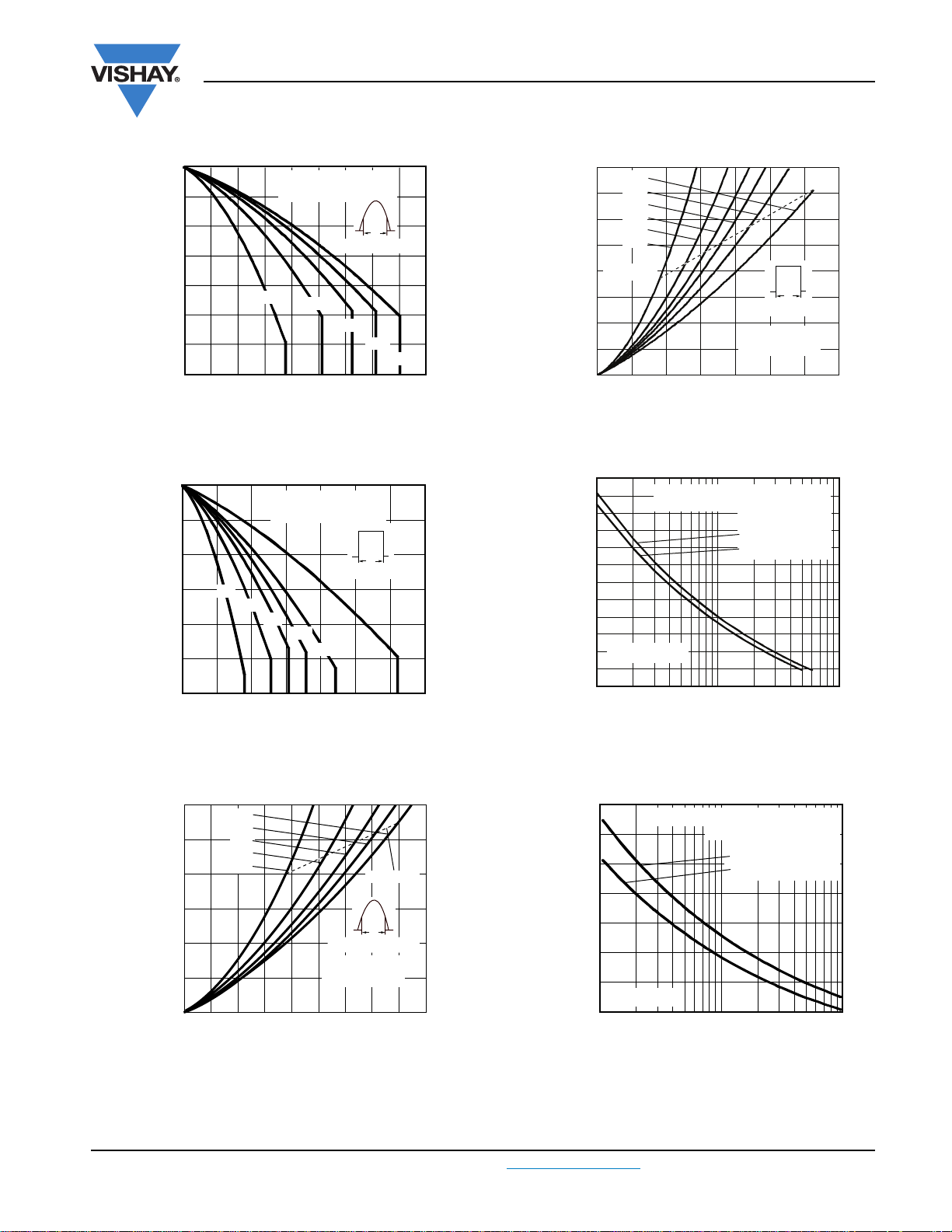
Fig. 1 - Current Rating Characteristics


150


80EPS.. Series


<![if ! IE]>

<![endif]>Maximum Allowable Case


140


RthJC (DC) = 0.35 K/W


<![if ! IE]>

<![endif]>Temperature (°C)

130


Ø


Conduction period


120

30°


60°


110


90°


120°


100


180°


DC


90


0

20

40

60

80

100

120

140

Average Forward Current (A)

Fig. 2 - Current Rating Characteristics


120

180°


<![if ! IE]>

<![endif]>ForwardAverageMaximum

<![if ! IE]>

<![endif]>(W)LossPower

100

120°


90°


60°


80

30°

RMS limit


60


40


Ø


Conduction angle


80EPS.. Series


20

TJ

= 150 °C

0

0

10

20

30

40

50

60

70

80

90

Average Forward Current (A)

Fig. 3 - Forward Power Loss Characteristics


160

DC


<![if ! IE]>

<![endif]>Maximum Average Forward


140

180°


120°


120

90°


<![if ! IE]>

<![endif]>Power Loss (W)

60°


100

30°


80

RMS limit


60


Ø


Conduction period

40


80EPS.. Series


20


TJ = 150 °C


0


0

20

40

60

80

100

120

140

Average Forward Current (A)

Fig. 4 - Forward Power Loss Characteristics


1600


At

any rated

load

condition and with


1400


rated VRRM applied following surge.


<![if ! IE]>

<![endif]>SineWave

<![if ! IE]>

<![endif]>Current(A)


Initial TJ = 150 °C


at 60 Hz 0.0083 s


1200


at 50 Hz 0.0100 s


1000


<![if ! IE]>

<![endif]>PeakHalf

<![if ! IE]>

<![endif]>Forward


800


600


80EPS.. Series


400


1

10


100

Number of Equal Amplitudr Halfe

Cycle Current Pulse (N)

Fig. 5 - Maximum Non-Repetitive Surge Current


1800

Maximum non-repetitive surge current


1600

versus pulse train duration.


Initial TJ = 150 °C


<![if ! IE]>

<![endif]>SineWave

<![if ! IE]>

<![endif]>Current(A)


1400

No voltage reapplied


Rated VRRM reapplied


1200


<![if ! IE]>

<![endif]>HalfPeak

<![if ! IE]>

<![endif]>Forward


1000


800


600


80EPS.. Series


400


0.01

0.1

1

Pulse Train Duration (s)

Fig. 6 - Maximum Non-Repetitive Surge Current

Document Number: 93524

For technical questions, contact: diodestech@vishay.com

www.vishay.com

Revision: 07-Jul-09


3

Loading...
+ 5 hidden pages