

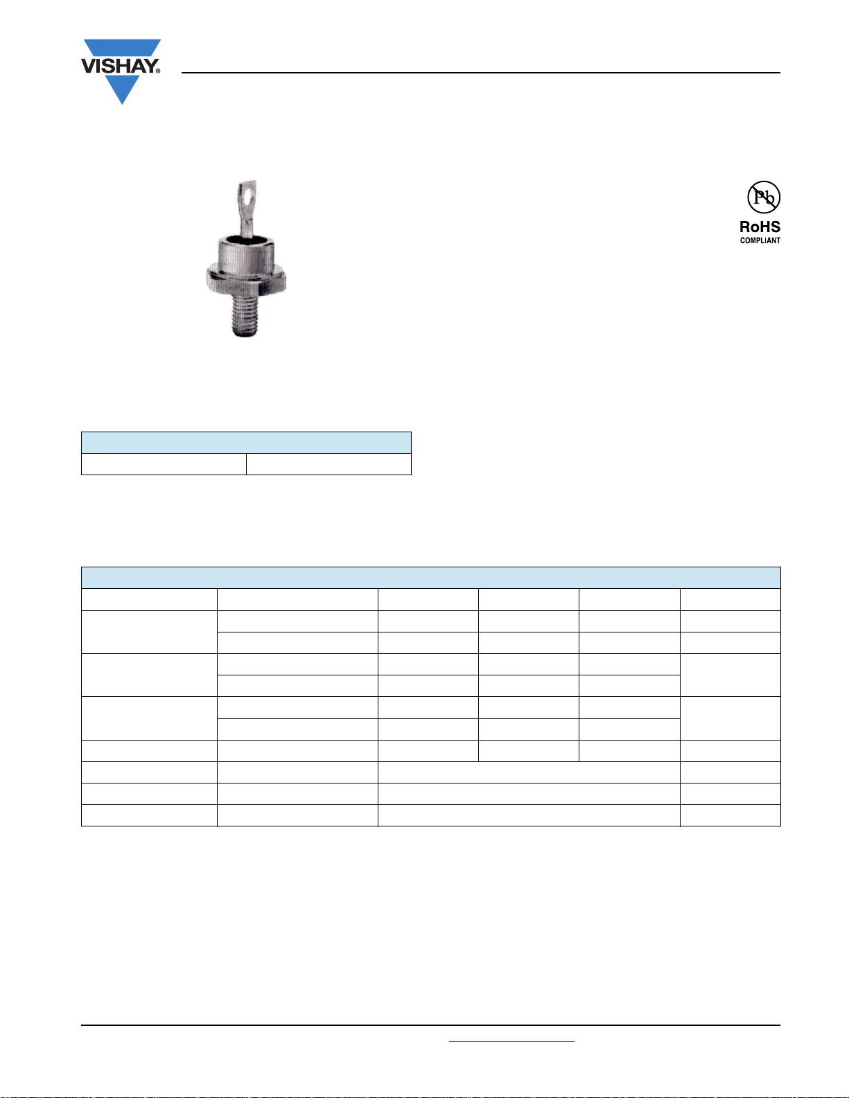
DO-203AB (DO-5)
PRODUCT SUMMARY
I
F(AV)
40HFL, 70HFL, 85HFL Series
Vishay High Power Products
Fast Recovery Diodes
(Stud Version), 40 A/70 A/85 A
FEATURES
• Short reverse recovery time
• Low stored charge
• Wide current range
• Excellent surge capabilities
• Stud cathode and stud anode versions
40 A/70 A/85 A
• Types up to 100 V
• Compliant to RoHS directive 2002/95/EC
TYPICAL APPLICATIONS
• DC power supplies
•Inverters
• Converters
• Choppers
• Ultrasonic systems
RRM
• Freewheeling diodes
MAJOR RATINGS AND CHARACTERISTICS
SYMBOL CHARACTERISTICS 40HFL 70HFL 85HFL UNITS
I
F(AV)
I
FSM
2
I
t
2
I
√t 11 300 34 650 85 560 I2√s
V
RRM
t
rr
T
J
Maximum T
50 Hz 400 700 1100
60 Hz 420 730 1151
50 Hz 800 2450 6050
60 Hz 730 2240 5523
Range 100 to 1000 V
Range - 40 to 125 °C
C
40 70 85 A
85 85 85 °C
A
A2s
See Recovery Characteristics table ns
Document Number: 93150 For technical questions, contact: ind-modules@vishay.com
Revision: 25-May-09 1
www.vishay.com

40HFL, 70HFL, 85HFL Series
Vishay High Power Products
Fast Recovery Diodes
(Stud Version), 40 A/70 A/85 A
ELECTRICAL SPECIFICATIONS
VOLTAGE RATINGS
V
, MAXIMUM
RRM
TYPE NUMBER
40HFL10S02, 40HFL10S05, 40HFL10S10
40HFL20S02, 40HFL20S05, 40HFL20S10 200 300
40HFL40S02, 40HFL40S05, 40HFL40S10 400 500
40HFL60S02, 40HFL60S05, 40HFL60S10 600 700
40HFL80S05, 40HFL80S10 800 900
40HFL100S05, 40HFL100S10 1000 1100
70HFL10S02, 70HFL10S05, 70HFL10S10
70HFL20S02, 70HFL20S05, 70HFL20S10 200 300
70HFL40S02, 70HFL40S05, 70HFL40S10 400 500
70HFL60S02, 70HFL60S05, 70HFL60S10 600 700
70HFL80S05, 70HFL80S10 800 900
70HFL100S05, 70HFL100S10 1000 1100
85HFL10S02, 85HFL10S05, 85HFL10S10
85HFL20S02, 85HFL20S05, 85HFL20S10 200 300
85HFL40S02, 85HFL40S05, 85HFL40S10 400 500
85HFL60S02, 85HFL60S05, 85HFL60S10 600 700
85HFL80S05, 85HFL80S10 800 900
85HFL100S05, 85HFL100S10 1000 1100
Note
(1)
Types listed are cathode case, for anode case add “R” to code, i.e. 40HFLR20S02, 85HFLR100S05 etc.
(1)
PEAK REPETITIVE
REVERSE VOLTAGE
T
= - 40 °C TO 125 °C
J
V
100 150
100 150
100 150
V
, MAXIMUM PEAK
RSM
NON-REPETITIVE
REVERSE VOLTAGE
T
= 25 °C TO 125 °C
J
V
I
, MAXIMUM PEAK REVERSE
FM
CURRENT AT RATED V
mA
T
= 25 °C TJ = 125 °C
J
0.1 10
0.1 15
0.1 20
RRM
www.vishay.com For technical questions, contact: ind-modules@vishay.com
2 Revision: 25-May-09
Document Number: 93150
40HFL, 70HFL, 85HFL Series
Fast Recovery Diodes
Vishay High Power Products
(Stud Version), 40 A/70 A/85 A
FORWARD CONDUCTION
PARAMETER SYMBOL TEST CONDITIONS 40HFL 70HFL 85HFL UNITS
Maximum average forward current
at maximum case temperature
Maximum RMS forward current I
Maximum peak repetitive forward current I
Maximum peak, one-cycle
non-repetitive forward current
2
Maximum I
Maximum I
t for fusing I2t
2
√t for fusing
(1)
Maximum value of threshold voltage V
Maximum value of forward slope resistance r
Maximum forward voltage drop V
Note
(1)I2
t for time tx = I2√t • √t
x
I
F(AV)
F(RMS)
FRM
I
FSM
180° conduction, half sine wave
Sinusoidal half wave, 30° conduction 220 380 470 A
t = 10 ms
t = 8.3 ms 420 730 1151
t = 10 ms
Sinusoidal half wave, 100
% V
reapplied,
RRM
initial T
= TJ maximum
J
Sinusoidal half wave,
40
63 110 134 A
400 700 1100
475 830 1308
no voltage reapplied,
t = 8.3 ms 500 870 1369
t = 10 ms
t = 8.3 ms 730 2240 5523
t = 10 ms
t = 8.3 ms 1030 3160 7810
= TJ maximum
initial T
J
100 % V
initial T
reapplied,
RRM
= TJ maximum
J
No voltage reapplied,
= TJ maximum
initial T
J
800 2450 6050
1130 3460 8556
I2√t t = 0.1 ms to 10 ms, no voltage reapplied 11 300 34 650 85 560 A2√s
F(TO)
F
FM
TJ = 125 °C
TJ = 25 °C, IFM = π x I
F(AV)
1.081 1.085 1.128 V
6.33 3.40 2.11 mΩ
1.95 1.85 1.75 V
70
85
75 °C
A
A
2
A
s
RECOVERY CHARACTERISTICS
PARAMETER SYMBOL TEST CONDITIONS
TJ = 25 °C, IF = 1 A to VR = 30 V,
/dt = 100 A/µs
Typical reverse
recovery time
t
- dI
rr
F
= 25 °C, - dIF/dt = 25 A/µs,
T
J
I
= π x rated I
FM
F(AV)
TJ = 25 °C, IF = 1 A to VR = 30 V,
- dI
Typical reverse
recovered charge
Q
rr
/dt = 100 A/µs
F
= 25 °C, - dIF/dt = 25 A/µs,
T
J
= π x rated I
I
FM
F(AV)
Document Number: 93150 For technical questions, contact: ind-modules@vishay.com
Revision: 25-May-09 3
40HFL... 70HFL... 85HFL...
S02 S05 S10 S02 S05 S10 S02 S05 S10
70 180 350 60 150 290 50 120 270
200 500 1000 200 500 1000 200 500 1000
160 750 3100 90 500 1600 70 340 1350
240 1300 6000 240 1300 6000 240 1300 6000
www.vishay.com
UNITS
ns
nC
40HFL, 70HFL, 85HFL Series
Vishay High Power Products
Fast Recovery Diodes
(Stud Version), 40 A/70 A/85 A
THERMAL AND MECHANICAL SPECIFICATIONS
PARAMETER SYMBOL TEST CONDITIONS 40HFL 70HFL 85HFL UNITS
Junction operating temperature range T
Storage temperature range T
Maximum thermal resistance,
junction to case
Maximum thermal resistance,
case to heatsink
Maximum allowable mounting torque
(+ 0 %, - 10 %)
Approximate weight
Case style JEDEC DO-203AB (DO-5)
Notes
(1)
Recommended for pass-through holes
(2)
Recommended for holed threaded heatsinks
J
Stg
R
thJC
R
thCS
DC operation 0.60 0.36 0.30
Mounting surface, smooth,
flat and greased
Not lubricated thread, tighting on nut
Lubricated thread, tighting on nut
Not lubricated thread, tighting on hexagon
Lubricated thread, tighting on hexagon
(1)
(1)
(2)
(2)
- 40 to 125
- 40 to 150
0.25
3.4 (30)
2.3 (20)
4.2 (37)
3.2 (28)
25
0.88
(lbf · in)
°C
K/W
N · m
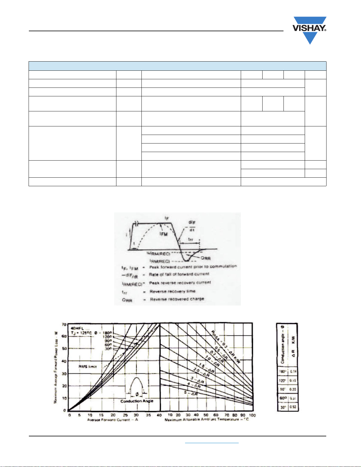
Fig. 1 - Reverse Recovery Time Test Waveform
Fig. 2 - Current Rating Nomogram (Sinusoidal Waveforms), 40HFL Series
www.vishay.com For technical questions, contact: ind-modules@vishay.com
4 Revision: 25-May-09
Document Number: 93150

40HFL, 70HFL, 85HFL Series
Fast Recovery Diodes
Vishay High Power Products
(Stud Version), 40 A/70 A/85 A
Fig. 3 - Current Rating Nomogram (Rectangular Waveforms), 40HFL Series
Fig. 4 - Current Rating Nomogram (Sinusoidal Waveforms), 70HFL Series
70HFL
Fig. 5 - Current Rating Nomogram (Rectangular Waveforms), 70HFL Series
Document Number: 93150 For technical questions, contact: ind-modules@vishay.com
Revision: 25-May-09 5
www.vishay.com

40HFL, 70HFL, 85HFL Series
Vishay High Power Products
85HFL
Fig. 6 - Current Rating Nomogram (Sinusoidal Waveforms), 85HFL Series
85HFL
Fast Recovery Diodes
(Stud Version), 40 A/70 A/85 A
Fig. 7 - Current Rating Nomogram (Rectangular Waveforms), 85HFL Series
Fig. 8 - Maximum High Level Forward Power Loss vs.
Average Forward Current, 40HFL Series
www.vishay.com For technical questions, contact: ind-modules@vishay.com
6 Revision: 25-May-09
Fig. 9 - Maximum High Level Forward Power Loss vs.
Average Forward Current, 70HFL Series
Document Number: 93150

40HFL, 70HFL, 85HFL Series
Fast Recovery Diodes
(Stud Version), 40 A/70 A/85 A
Fig. 10 - Maximum High Level Forward Power Loss vs.
Average Forward Current, 85HFL Series
Vishay High Power Products
Fig. 13 - Maximum Forward Voltage vs. Forward Current,
85HFL Series
Fig. 11 - Maximum Forward Voltage vs. Forward Current,
40HFL Series
Fig. 12 - Maximum Forward Voltage vs. Forward Current,
70HFL Series
Document Number: 93150 For technical questions, contact: ind-modules@vishay.com
Revision: 25-May-09 7
Fig. 14 - Average Forward Current vs. Maximum Allowable
Case Temperature, 40HFL Series
Fig. 15 - Average Forward Current vs. Maximum Allowable
Case Temperature, 70HFL Series
www.vishay.com

40HFL, 70HFL, 85HFL Series
Vishay High Power Products
Fig. 16 - Average Forward Current vs. Maximum Allowable
Case Temperature, 85HFL Series
Fast Recovery Diodes
(Stud Version), 40 A/70 A/85 A
Fig. 17 - Maximum Non-Repetitive Surge Current
vs. Number of Current Pulses, All Series
Fig. 18 - Maximum Transient Thermal Impedance, Junction to Case vs. Pulse Duration, All Series
Fig. 19 - Typical Reverse Recovery Time vs.
Rate of Fall of Forward Current, 40HFL...S02 Series
www.vishay.com For technical questions, contact: ind-modules@vishay.com
8 Revision: 25-May-09
Fig. 20 - Typical Recovered Charge vs.
Rate of Fall of Forward Current, 40HFL...S02 Series
Document Number: 93150

40HFL, 70HFL, 85HFL Series
Fast Recovery Diodes
(Stud Version), 40 A/70 A/85 A
Fig. 21 - Typical Reverse Recovery Time vs.
Rate of Fall of Forward Current, 40HFL...S05 Series
Vishay High Power Products
Fig. 24 - Typical Recovered Charge vs.
Rate of Fall of Forward Current, 40HFL...S10 Series
Fig. 22 - Typical Recovered Charge vs.
Rate of Fall of Forward Current, 40HFL...S05 Series
Fig. 23 - Typical Reverse Recovery Time vs.
Rate of Fall of Forward Current, 40HFL...S10 Series
Document Number: 93150 For technical questions, contact: ind-modules@vishay.com
Revision: 25-May-09 9
Fig. 25 - Typical Reverse Recovery Time vs.
Rate of Fall of Forward Current, 70HFL...S02 Series
Fig. 26 - Typical Recovered Charge vs.
Rate of Fall of Forward Current, 70HFL...S02 Series
www.vishay.com

40HFL, 70HFL, 85HFL Series
Vishay High Power Products
Fig. 27 - Typical Reverse Recovery Time vs.
Rate of Fall of Forward Current, 70HFL...S05 Series
Fast Recovery Diodes
(Stud Version), 40 A/70 A/85 A
Fig. 30 - Typical Recovered Charge vs.
Rate of Fall of Forward Current, 70HFL...S10 Series
Fig. 28 - Typical Recovered Charge vs.
Rate of Fall of Forward Current, 70HFL...S05 Series
Fig. 29 - Typical Reverse Recovery Time vs.
Rate of Fall of Forward Current, 70HFL...S10 Series
www.vishay.com For technical questions, contact: ind-modules@vishay.com
10 Revision: 25-May-09
Fig. 31 - Typical Reverse Recovery Time vs.
Rate of Fall of Forward Current, 85HFL...S02 Series
Fig. 32 - Typical Recovered Charge vs.
Rate of Fall of Forward Current, 85HFL...S02 Series
Document Number: 93150

40HFL, 70HFL, 85HFL Series
Fast Recovery Diodes
(Stud Version), 40 A/70 A/85 A
Fig. 33 - Typical Reverse Recovery Time vs.
Rate of Fall of Forward Current, 85HFL...S05 Series
Vishay High Power Products
Fig. 35 - Typical Reverse Recovery Time vs.
Rate of Fall of Forward Current, 85HFL...S10 Series
Fig. 34 - Typical Recovered Charge vs.
Rate of Fall of Forward Current, 85HFL...S05 Series
LINKS TO RELATED DOCUMENTS
Dimensions www.vishay.com/doc?95312
Document Number: 93150 For technical questions, contact: ind-modules@vishay.com
Revision: 25-May-09 11
Fig. 36 - Typical Recovered Charge vs.
Rate of Fall of Forward Current, 85HFL...S10 Series
www.vishay.com

Legal Disclaimer Notice
Vishay
Disclaimer
All product specifications and data are subject to change without notice.
Vishay Intertechnology, Inc., its affiliates, agents, and employees, and all persons acting on its or their behalf
(collectively, “Vishay”), disclaim any and all liability for any errors, inaccuracies or incompleteness contained herein
or in any other disclosure relating to any product.
Vishay disclaims any and all liability arising out of the use or application of any product described herein or of any
information provided herein to the maximum extent permitted by law. The product specifications do not expand or
otherwise modify Vishay’s terms and conditions of purchase, including but not limited to the warranty expressed
therein, which apply to these products.
No license, express or implied, by estoppel or otherwise, to any intellectual property rights is granted by this
document or by any conduct of Vishay.
The products shown herein are not designed for use in medical, life-saving, or life-sustaining applications unless
otherwise expressly indicated. Customers using or selling Vishay products not expressly indicated for use in such
applications do so entirely at their own risk and agree to fully indemnify Vishay for any damages arising or resulting
from such use or sale. Please contact authorized Vishay personnel to obtain written terms and conditions regarding
products designed for such applications.
Product names and markings noted herein may be trademarks of their respective owners.
Document Number: 91000 www.vishay.com
Revision: 18-Jul-08 1
 Loading...